1998 JAGUAR X308 Fuel pump relay
[x] Cancel search: Fuel pump relayPage 44 of 2490

Electrically Programmable
R
ead-Only memory
EPROM
Ele
c
tronic Secondary Air
Injection
EAIRA p
ump-driven system for providing seco
ndary air using an electric air pump
Engine C
ontrol Module
ECM
End of dashEODR
e
ferring to a vehicle fascia, eg EOD air vent
Engine
C
oolant Level
ECL
Engine
C
oolant
Temperature
ECT
ECT Sen s
or
ECTSTherm
i
stor which provides engine coolant temperature signal to the ECM to
trigger enrichment circuits which increase injector 'on' time for cold start and
warm-up
Engine s
peed
RP
M
Environ m
ental Protection
Agency
EPA
Evaporative EmissionEVAPSy stem designed to prevent fu
el vapor from escaping into the atmosphere.
Typically includes a charcoal filled canister to absorb fuel vapor
Evaporative Emission
Control ValveEVAPP
Exhaust G
as Recirculation
EGRSys
t
em which reduces NOx emissions by adding exhaust gases to the
incoming fuel/air charge
Exhaus t G
as Recirculation
Solenoid Vacuum Valve
EGRS
Exhaus t G
as Recirculation
Temperature Sensor
EGRT Sen s
or
Exhaus
t G
as Recirculation
Valve
EGRV
F
F a
n Control
FCEngine
cooling fan control
F
e
deral Motor Vehicle
Safety Standard (US)
FMV S
S
Fi
gur
e
Fi
g.Illustrati
on reference
Flash
E
lectrically Erasable
Programmable Read-Only
Memory
FEE PR
OM
Flash
E
rasable
Programmable Read-Only
Memory
FEP R
OM
Flywhee
l
Sensor
CKFSSens
or moun
ted so as to be
triggered by each flywheel ring gear tooth to give
an engine speed signal
Fue l
Injectors
FISol
e
noid operated devices that spray a metered quantity of fuel into the inlet
ports
F u
el Pressure Regulator
Control
FP RCControls fuel pressure regu l
ator; used primarily to
give extra fuel at cold
start-up
Fue l
Pump
FP
Fue
l
Pump Monitor
FP
MMonitors operation of fuel pump
Fue l
Pump Relay
FP
R
Fu
el rich/lean
Q
u
alitative evaluation
of air/fuel ratio based on a ratio known as
stoichiometry, or 14.7:1 (Lambda)
F u
ll Scale Deflection
FSDTh
e
maximum indication point on
an analogue meter or gauge
G
Gene
rator
GENRot
a
ting machine which converts mechanical energy into electrical energy
G
r
amme centimeter
gcm
Gramm
e
(force)
gf
Gramm
e
(mass)
g
GroundGNDEle
c
trical conductor used
as a common return for an electrical circuit or
circuits, and with a relative zero potential
H
Hard f a
ult
A
fau
lt currently present in the system
HeadlampHL
Heat
ed Oxygen
Sensor
HO2SElectrically
h
eated oxygen sensor which induces fueling corrections
Hertz (frequency)HzFrequ
e
ncy, one cycle per second
High
Moun
ted Stoplamp
HMSL
Page 527 of 2490
E
ngine Management System Components
Electronic Throt
tle
The
electronic throttle assembly, in resp
onse to signals from both the driver and the ECM, adjusts idle speed, sets the
throttle valve to the position requested by the driver's accelerator / throttle pedal, cruise and traction control, power
limitation and catalyst warm-up.
Mass
Air Flow Meter
The sensor i
s located in the air flow mete
r assembly and outputs an analogue voltag e to the ECM. This sensor measures air
flow into the engine inlet system and is calibrated to measure kg / hour.
In
take Air Temperature
Th
e intake air temperature sensor is loca
ted in the air flow meter assembly and outputs an analogue voltage to the ECM.
The ECM will substitute a default value eq ual to 50°C should this sensor fail.
Fuel Injectors
The eigh
t bottom fed fuel injectors are located in the fuel rails. Th
e fuel injectors are electromagnetic solenoid valves
controlled by the ECM. The pulse time for the injector combined with the fuel pr essure determines the volume of fuel
injected to the manifold.
Fue
l Delivery
The fu
el pump provides fuel to the fuel rail where the circulat
ing pressure is controlled by a pressure regulator valve; excess
fuel is returned to the fuel tank.
The pressure regulator valve is controlled by manifold depression so that fuel delivery pressure is maintained at
approximately 3 bar above manifold pressure.
Fuel Pump
Relay
The ECM controls thi
s component for normal
engine running. The security system may disable this relay via communication
with the ECM.
Fuel Lev
el Sensing
The tank fuel
is measured by the fuel le
vel sensor . This signal is used by the ECM as an in put to certain diagnostics.
Eva
porative Valve
Excess vapour
formed in the fuel tank is
absorbed into the evaporative emission pu rge control canister. While the engine is
running, the fuel absorbed in the canister is gradually purged back into the engine. The rate of purging is governed by
engine operating conditions and vapour concentration level. Operating conditions which affect the purge rate are:
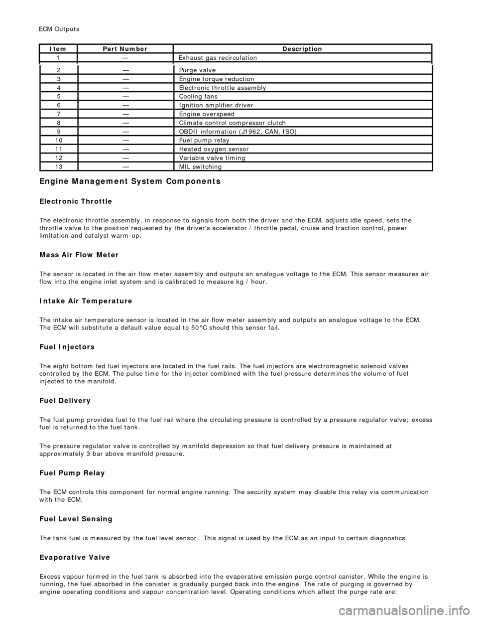
2—Purge
valve
3—Engine
torque reduction
4—E
lectronic throttle assembly
5—Coo
ling fans
6—Ignition amplifier driver
7—Engine overspeed
8—Cli
mate control compressor clutch
9—O
BDII information (J1962, CAN, ISO)
10—F
uel pump relay
11—Heat
ed oxygen sensor
12—Vari
able valve timing
13—MIL sw
itching
ECM Out
puts
It
em
Par
t Number
De
scription
1—Exhaus
t gas recirculation
Page 1021 of 2490
CAUTI
ON: When probing connectors to take
measurements in the course of the pinpoint tests, use the adaptor kit,
part number 3548-1358-00.
• NOTE: When performing electrical voltag e or resistance tests, always use a digital multimeter (DMM) accurate to 3
decimal places, and with an up-t o-date calibration certificate. When testing resistance, always take the resistance of the
DMM leads into account.
• NOTE: Check and rectify basic faults before beginning diagnostic ro utines involving pinpoint tests.
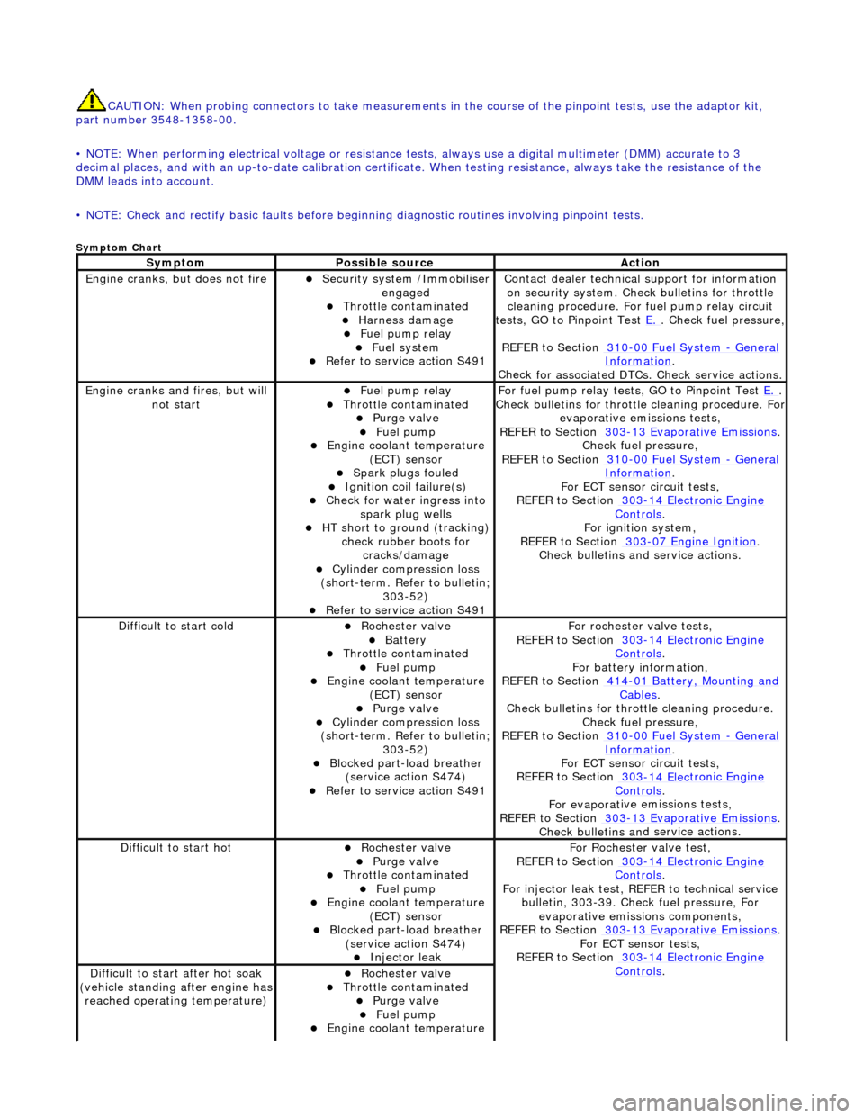
Sy
mptom Chart
Sy
mptom
Possib
le source
Acti
on
Engine
cranks, but does not fire
Secu
rity system /Immobiliser
engaged
Thr
ottle contaminated
Harness damage
F
uel pump relay
Fue
l system
R
efer to service action S491
Contact dealer techn
ical
support for information
on security system. Chec k bulletins for throttle
cleaning procedure. For fuel pump relay circuit
tests, GO to Pinpoint Test E.
.
Check fuel pressure,
REFER to Section 310
-00
Fuel System
- Gen
eral
Informati
on
.
Chec
k for associated DTCs
. Check service actions.
Engine
cranks and fires, but will
not start
F
uel pump relay
Thr
ottle contaminated
Purge
valve
Fue
l pump
Engine coolan
t temperature
(ECT) sensor
Spark plugs
fouled
Ignition coil
failure(s)
Check f
or water ingress into
spark plug wells
HT sho
rt to ground (tracking)
check rubber boots for cracks/damage
Cyl
inder compression loss
(short-term. Refer to bulletin;
303-52)
R
efer to service action S491
F
or fuel pump relay tests,
GO to Pinpoint Test E.
.
Check bull
etins for throttle cleaning procedure. For
evaporative emissions tests,
REFER to Section 303
-1
3 Evaporative Emissions
. Chec
k fuel pressure,
REFER to Section 310
-00
Fuel System
- Ge
neral
Informati
on
.
F
or ECT sensor circuit tests,
REFER to Section 303
-14 Elec
tronic Engine
Controls.
For ign
ition system,
REFER to Section 303
-07
Engine Ignition
.
Check bulletins an d service
actions.
D
ifficult to start cold
Roc
hester valve
Batt
ery
Thr
ottle contaminated
Fue
l pump
Engine coolan
t temperature
(ECT) sensor
Purge
valve
Cyl
inder compression loss
(short-term. Refer to bulletin;
303-52)
Blocked part-load breather (
service action S474)
R
efer to service action S491
F
or rochester valve tests,
REFER to Section 303
-14 Elec
tronic Engine
Controls.
F
or battery information,
REFER to Section 414
-0
1 Battery, Mounting and
Cables.
Check bull
etins for throttle cleaning procedure.
Check fuel pressure,
REFER to Section 310
-00
Fuel System
- Ge
neral
Informati
on
.
F
or ECT sensor circuit tests,
REFER to Section 303
-14 Elec
tronic Engine
Controls.
For evaporat
ive emissions tests,
REFER to Section 303
-1
3 Evaporative Emissions
. Check bulletins an
d
service actions.
D
ifficult to start hot
Roc
hester valve
Purge
valve
Thr
ottle contaminated
Fue
l pump
Engine coolan
t temperature
(ECT) sensor
Blocked part-load breather (
service action S474)
Injec
tor leak
F
or Rochester
valve test,
REFER to Section 303
-14 Elec
tronic Engine
Controls.
Fo
r injector leak test, REFER to technical service
bulletin, 303-39. Check fuel pressure, For evaporative emissions components,
REFER to Section 303
-1
3 Evaporative Emissions
. F
or ECT sensor tests,
REFER to Section 303
-14 Elec
tronic Engine
Controls. D
ifficult to start after hot soak
(vehicle standing after engine has
reached operating temperature)
Roc
hester valve
Thr
ottle contaminated
Purge
valve
Fue
l pump
Engine coolan
t temperature
Page 1022 of 2490
(ECT) se
nsor
Blocked part-load breather
(s
ervice action S474)
Injec
t
or leak
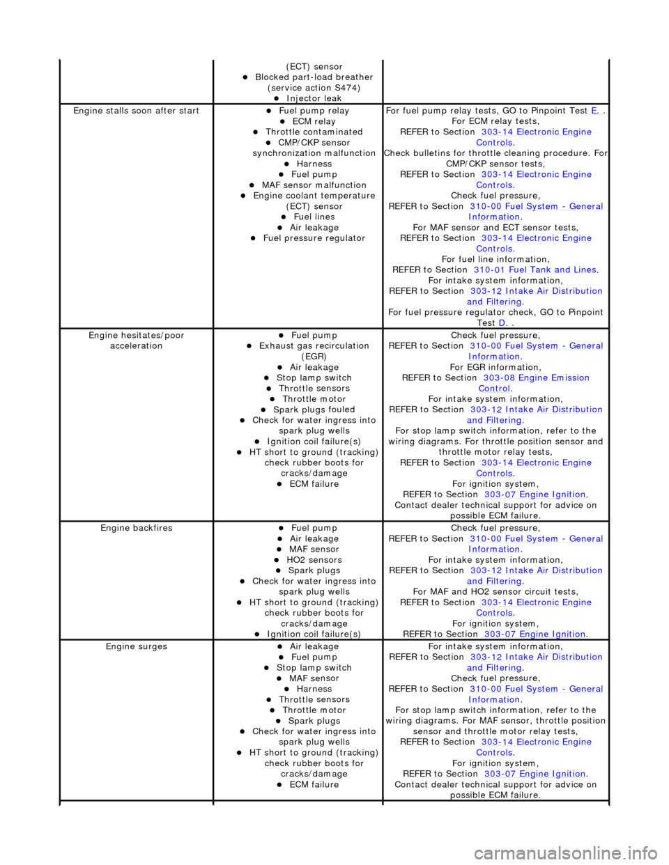
Engine stalls
soon
after start
F
u
el pump relay
ECM relay Thr
o
ttle contaminated
CMP/CKP sen
s
or
synchronization malfunction
Harness Fuel
pump
MAF
s
ensor malfunction
Engine coolan
t
temperature
(ECT) sensor
Fue l
lines
Air leakage Fu
el pressure regulator
F
o
r fuel pump relay tests,
GO to Pinpoint Test E.
.
F or ECM
relay tests,
REFER to Section 303
-14 Elec tronic En
gine
Controls.
Check bull etins for throttl
e cleaning procedure. For
CMP/CKP sensor tests,
REFER to Section 303
-14 Elec tronic En
gine
Controls.
Chec k fu
el pressure,
REFER to Section 310
-00 Fu
el System
- Ge
n
eral
Informati
o
n
.
F or MAF sensor and
ECT sensor tests,
REFER to Section 303
-14 Electronic En
gine
Controls.
For fuel l
ine information,
REFER to Section 310
-01
Fuel Tank and Lines
.
F or i
ntake system information,
REFER to Section 303
-1 2
Intake Air Distribution
and F
ilt
ering
.
F o
r fuel pressure regulato
r check, GO to Pinpoint
Test D.
.
Engine h e
sitates/poor
acceleration
Fue l
pump
Exhaus
t gas
recirculation
(EGR)
Air leakage Stop lamp swi t
ch
Throttl
e
sensors
Throttl
e
motor
Spark plugs
fouled
Check f
o
r water ingress into
spark plug wells
Ignition coil fail
ure(s)
HT sho
rt to ground (tracking)
check rubber
boots for
cracks/damage
ECM failu r
e
Chec
k fu
el pressure,
REFER to Section 310
-00 Fu
el System
- Ge
n
eral
Informati
o
n
.
F o
r EGR information,
REFER to Section 303
-08 En gin
e Emission
Control.
F or i
ntake system information,
REFER to Section 303
-1 2
Intake Air Distribution
and F
ilt
ering
.
F or stop l
amp switch in
formation, refer to the
wiring diagrams. For throttle position sensor and throttle motor relay tests,
REFER to Section 303
-14 Elec tronic En
gine
Controls.
For ign i
tion system,
REFER to Section 303
-07 En
gine Ignition
.
Contact dealer techn i
cal
support for advice on
possible ECM failure.
Engine ba ckfiresFuel
pump
Air leakage MAF s
e
nsor
HO2 sensors Spark plugs
Check fo
r water ingress into
spark plug wells
HT short to ground (tracking) check rubber
boots for
cracks/damage
Ignition coil fail
ure(s)
Chec
k fu
el pressure,
REFER to Section 310
-00 Fu
el System
- Ge
n
eral
Informati
o
n
.
F or i
ntake system information,
REFER to Section 303
-1 2
Intake Air Distribution
and F
ilt
ering
.
For MAF and HO2
sensor circuit tests,
REFER to Section 303
-14 Electronic En
gine
Controls.
For igni
tion system,
REFER to Section 303
-07 En
gine Ignition
.
Engine
s
urges
Air leakage Fue
l
pump
Stop lamp swi
t
ch
MAF s
e
nsor
Harness Throttl
e
sensors
Throttl
e
motor
Spark plugs
Check fo
r water ingress into
spark plug wells
HT sho rt to ground (tracking)
check rubber
boots for
cracks/damage
ECM failu r
e
F
or i
ntake system information,
REFER to Section 303
-1 2
Intake Air Distribution
and F
ilt
ering
.
Chec k fu
el pressure,
REFER to Section 310
-00 Fu
el System
- Gen
e
ral
Informati
o
n
.
F or stop l
amp switch in
formation, refer to the
wiring diagrams. For MAF se nsor, throttle position
sensor and throttle motor relay tests,
REFER to Section 303
-14 Elec tronic En
gine
Controls.
For ign i
tion system,
REFER to Section 303
-07 En
gine Ignition
.
Contact dealer techn i
cal
support for advice on
possible ECM failure.
Page 1023 of 2490
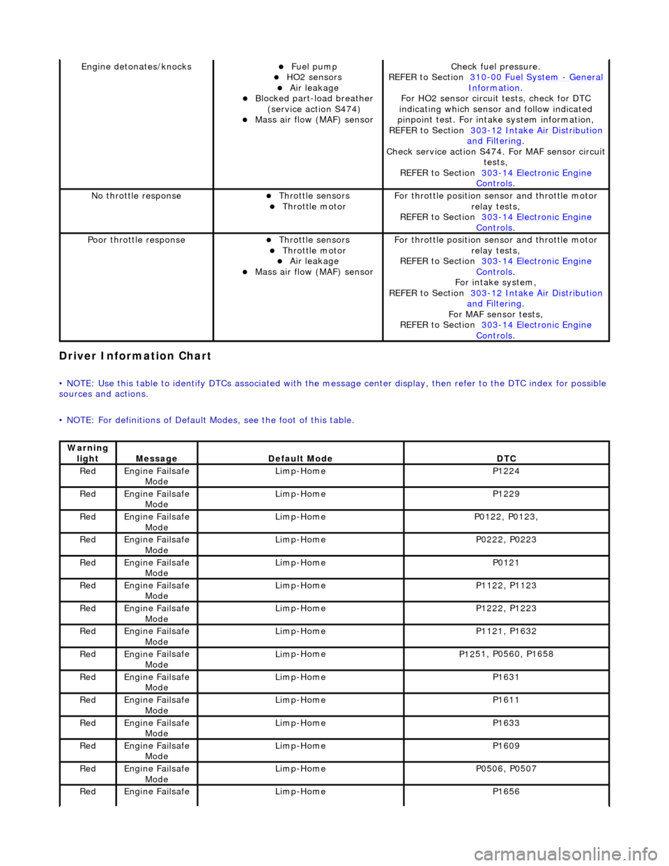
Driver Informa
tion Chart
•
NOTE: Use this table to identify DTCs associated with the me
ssage center display, then refer to the DTC index for possible
sources and actions.
• NOTE: For definitions of Default Modes, see the foot of this table.
Engine deton
ates/knocks
Fue
l pump
HO2 sensors Air leakage Blocked part-load breather
(
service action S474)
Mass ai
r flow (MAF) sensor
Chec
k fuel pressure.
REFER to Section 310
-00
Fuel System
- Gen
eral
Informati
on
.
F
or HO2 sensor circuit
tests, check for DTC
indicating which sensor and follow indicated
pinpoint test. For intake system information,
REFER to Section 303
-1
2 Intake Air Distribution
and F
iltering
.
Check service
action S474. For MAF sensor circuit
tests,
REFER to Section 303
-14 Elec
tronic Engine
Controls.
No
throttle response
Throttl
e sensors
Throttl
e motor
F
or throttle position se
nsor and throttle motor
relay tests,
REFER to Section 303
-14 Elec
tronic Engine
Controls.
Poor throttle responseThrottl
e sensors
Throttl
e motor
Air leakage Mass ai
r flow (MAF) sensor
F
or throttle position se
nsor and throttle motor
relay tests,
REFER to Section 303
-14 Elec
tronic Engine
Controls.
Fo
r intake system,
REFER to Section 303
-1
2 Intake Air Distribution
and F
iltering
.
For MAF
sensor tests,
REFER to Section 303
-14 Elec
tronic Engine
Controls.
Warning
lightMess
age
De
fault Mode
DT
C
Re
d
Engine
Failsafe
Mode
Lim
p-Home
P1224
Re
d
Engine
Failsafe
Mode
Lim
p-Home
P1229
Re
d
Engine
Failsafe
Mode
Lim
p-Home
P01
22, P0123,
Re
d
Engine
Failsafe
Mode
Lim
p-Home
P02
22, P0223
Re
d
Engine
Failsafe
Mode
Lim
p-Home
P0121
Re
d
Engine
Failsafe
Mode
Lim
p-Home
P11
22, P1123
Re
d
Engine
Failsafe
Mode
Lim
p-Home
P12
22, P1223
Re
d
Engine
Failsafe
Mode
Lim
p-Home
P11
21, P1632
Re
d
Engine
Failsafe
Mode
Lim
p-Home
P12
51, P0560, P1658
Re
d
Engine
Failsafe
Mode
Lim
p-Home
P1631
Re
d
Engine
Failsafe
Mode
Lim
p-Home
P1611
Re
d
Engine
Failsafe
Mode
Lim
p-Home
P1633
Re
d
Engine
Failsafe
Mode
Lim
p-Home
P1609
Re
d
Engine
Failsafe
Mode
Lim
p-Home
P05
06, P0507
Re
d
Engine
Failsafe
Lim
p-Home
P1656
Page 1028 of 2490
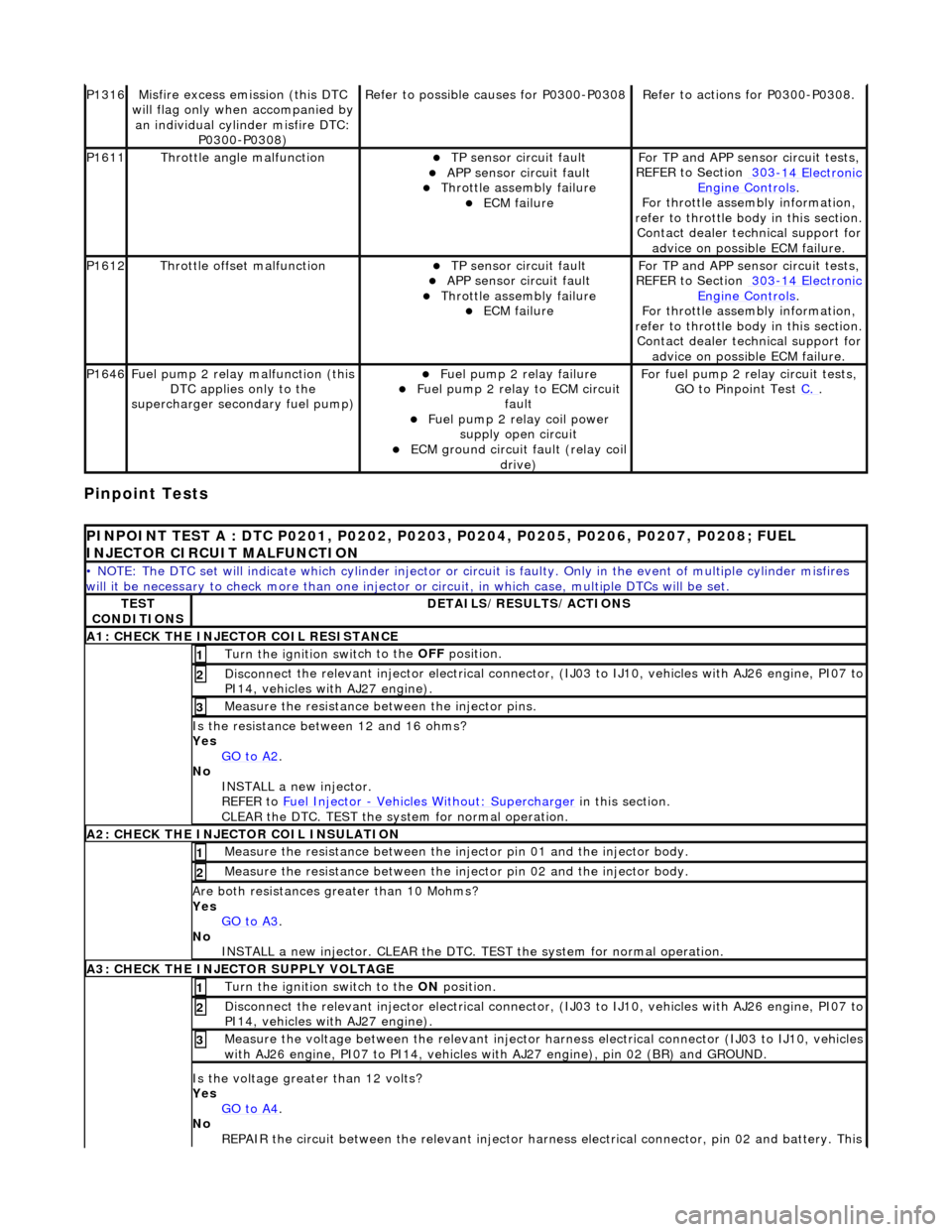
Pinpoint Tests
P1316Mi
sfire excess emission (this DTC
will flag only when accompanied by an individual cylinder misfire DTC: P0300-P0308)
Re
fer to possible causes for P0300-P0308
R
e
fer to actions for P0300-P0308.
P1611Thr
o
ttle angle malfunction
TP sensor
ci
rcuit fault
APP sensor circuit faul
t Throttle
assembly failure
ECM failu
r
e
F
or TP and APP
sens
or circuit tests,
REFER to Section 303
-14 El
ectronic
Engine
C
ontrols
.
F o
r throttle assembly information,
refer to throttle body in this section.
Contact dealer technical support for advice on possible ECM failure.
P1612Throttl e
offset malfunction
TP sensor
ci
rcuit fault
APP sensor circuit faul
t Throttle
assembly failure
ECM failu
r
e
F
or TP and APP
sens
or circuit tests,
REFER to Section 303
-14 El
ectronic
Engine
C
ontrols
.
F o
r throttle assembly information,
refer to throttle body in this section.
Contact dealer technical support for advice on possible ECM failure.
P1646Fu
el pump 2 relay malfunction (this
DTC applies only to the
supercharger secondary fuel pump)
Fu
el pump 2 relay failure
Fu
el pump 2 relay to ECM circuit
fault
Fu
el pump 2 relay coil power
supply open circuit
ECM ground circuit faul t (relay coil
drive)
For fuel pump 2 r
elay circuit tests,
GO to Pinpoint Test C.
.
PI
NPOINT TEST A : DTC P0201, P0202, P0203, P0204, P0205, P0206, P0207, P0208; FUEL
INJECTOR CIRCUIT MALFUNCTION
• NOTE
: The DTC set will indicate which cylinder injector or circ
uit is faulty. Only in the event of multiple cylinder misfires
will it be necessary to chec k more than one injector or circuit, in which case, multiple DTCs will be set.
TES
T
CONDITIONS
D E
TAILS/RESULTS/ACTIONS
A1
: CH
ECK THE INJECTOR COIL RESISTANCE
Turn the ignition swi
t
ch to the OFF
position.
1
Disconne
ct the relevant injector electrical connector
, (IJ03 to IJ10, vehicles with AJ26 engine, PI07 to
PI14, vehicles with AJ27 engine).
2
Meas ure t
he resistance between the injector pins.
3
Is
t
he resistance between 12 and 16 ohms?
Yes GO to A2
.
No
INST
ALL a new injector.
REFER to Fuel Injector
- Ve hicles With
out: Supercharger
in this
section.
CLEAR the DTC. TEST the system for normal operation.
A2: CHECK
THE INJECTOR COIL INSULATION
Meas
ure t
he resistance between the inje
ctor pin 01 and the injector body.
1
Measure t
he resistance between the inje
ctor pin 02 and the injector body.
2
Are both re
sistances greater than 10 Mohms?
Yes GO to A3
.
No
INST
ALL a new injector. CLEAR the DTC. TE
ST the system for normal operation.
A3: CHECK THE INJECTOR
SUPPLY VOLTAGE
Turn the ignition swi
t
ch to the ON
position.
1
Disconne
ct the relevant injector electrical connector
, (IJ03 to IJ10, vehicles with AJ26 engine, PI07 to
PI14, vehicles with AJ27 engine).
2
Meas ure t
he voltage between the relevant injector harness electrical connector (IJ03 to IJ10, vehicles
with AJ26 engine, PI07 to PI 14, vehicles with AJ27 engine), pin 02 (BR) and GROUND.
3
Is the volt
age greater than 12 volts?
Yes GO to A4
.
No
R
EPAIR the circuit between the relevant injector harn
ess electrical connector, pin 02 and battery. This
Page 1030 of 2490
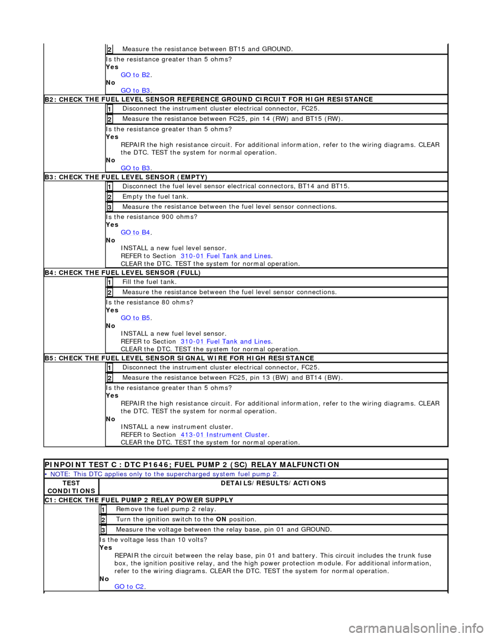
Measure t
he resistance
between BT15 and GROUND.
2
Is the res
istance greater than 5 ohms?
Yes GO to B2
.
No
GO to B3
.
B2: CHECK THE FUEL
LEVEL SENSOR REFERE
NCE GROUND CIRCUIT FOR HIGH RESISTANCE
Disc
onnect the instrument cluster electrical connector, FC25.
1
Meas
ure t
he resistance between FC25, pin 14 (RW) and BT15 (RW).
2
Is the res
istance greater than 5 ohms?
Yes REPAIR the high resistance circui t. For additional information, refer to the wiring diagrams. CLEAR
the DTC. TEST the system for normal operation.
No GO to B3
.
B3: CHECK THE FUEL
LEVEL SENSOR (EMPTY)
Di
sc
onnect the fuel level sensor electrical connectors, BT14 and BT15.
1
Empty the fuel
tank. 2
Measure t
he resistance between the
fuel level sensor connections.
3
Is t
he resistance 900 ohms?
Yes GO to B4
.
No
INST
ALL a new fuel level sensor.
REFER to Section 310
-0 1
Fuel Tank and Lines
.
CLEAR t h
e DTC. TEST the system for normal operation.
B4:
CHECK
THE FUEL LEVEL SENSOR (FULL)
Fi
ll
the fuel tank.
1
Meas
ure t
he resistance between the
fuel level sensor connections.
2
Is
the resistance 80 ohms?
Yes GO to B5
.
No
INST
ALL a new fuel level sensor.
REFER to Section 310
-0 1
Fuel Tank and Lines
.
CLEAR t h
e DTC. TEST the system for normal operation.
B
5
: CHECK THE FUEL LEVEL SENSOR SIGNAL WIRE FOR HIGH RESISTANCE
Di
sc
onnect the instrument cluster electrical connector, FC25.
1
Meas
ure t
he resistance between FC25, pin 13 (BW) and BT14 (BW).
2
Is th
e res
istance greater than 5 ohms?
Yes REPAIR the high resistance circui t. For additional information, refer to the wiring diagrams. CLEAR
the DTC. TEST the system for normal operation.
No INSTALL a new instrument cluster.
REFER to Section 413
-01
Instrume
nt Cluster
.
CLEAR t h
e DTC. TEST the system for normal operation.
P
INPOINT TEST C : DTC P1646; FU
EL PUMP 2 (SC) RELAY MALFUNCTION
•
NO
TE: This DTC applies only to the
supercharged system fuel pump 2.
TES
T
CONDITIONS
D E
TAILS/RESULTS/ACTIONS
C
1
: CHECK THE FUEL PUMP 2 RELAY POWER SUPPLY
R
e
move the fuel pump 2 relay.
1
Turn the ignition swi
t
ch to the
ON position.
2
Meas
ure t
he voltage between the
relay base, pin 01 and GROUND.
3
Is the volt
age less than 10 volts?
Yes REPAIR the circuit between the rela y base, pin 01 and battery. This circuit includes the trunk fuse
box, the ignition positive relay, and the high power protection module. For additional information,
refer to the wiring diagrams. CLEAR the DTC. TEST the system for normal operation.
No GO to C2
.
Page 1031 of 2490
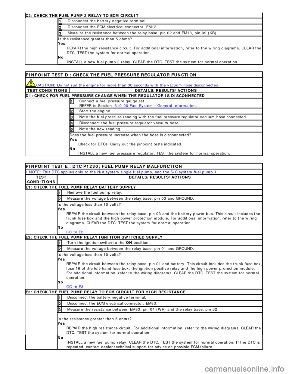
C2: CHECK THE FUEL
PUMP 2 RELAY TO ECM CIRCUIT
Di
sconnect the battery negative terminal.
1
D
isconnect the ECM electrical connector, EM13.
2
Meas
ure the resistance between the rela
y base, pin 02 and EM13, pin 09 (KB).
3
Is th
e resistance greater than 5 ohms?
Yes REPAIR the high resistance circuit. For additional information, refer to the wiring diagrams. CLEAR the
DTC. TEST the system for normal operation.
No INSTALL a new fuel pump 2 relay. CLEAR the DT C. TEST the system for normal operation.
P
INPOINT TEST D : CHECK THE FUEL PRESSURE REGULATOR FUNCTION
CAUTI
ON: Do not run the engine for more than
30 seconds with the vacuum hose disconnected.
T
EST CONDITIONS
D
ETAILS/RESULTS/ACTIONS
D
1: CHECK FOR FUEL PRESSURE CHANGE
WHEN THE REGULATOR IS DISCONNECTED
Connect a
fuel pressure gauge set,
REFER to Section 310
-00
Fuel System
-
General Informati
on
. 1
St
art the engine.
2
N
ote the fuel pressure readin
g with the fuel pressure regu lator vacuum hose connected.
3
Di
sconnect the fuel pressu
re regulator vacuum hose.
4
N
ote the new reading.
5
Doe
s the fuel pressure increase when the hose is disconnected?
Yes Check for DTCs. Carry out the pinpoint tests indicated.
No INSTALL a new fuel presssure regulator. TEST the system for normal operation.
P
INPOINT TEST E : DTC P1230;
FUEL PUMP RELAY MALFUNCTION
•
NOTE: This DTC applies only to the N/A system si
ngle fuel pump, and the S/C system fuel pump 1
TE
ST
CONDITIONS
D
ETAILS/RESULTS/ACTIONS
E1
: CHECK THE FUEL PUMP
RELAY BATTERY SUPPLY
R
emove the fuel pump relay.
1
Meas
ure the voltage between the
relay base, pin 03 and GROUND.
2
Is th
e voltage less than 10 volts?
Yes REPAIR the circuit between the rela y base, pin 03 and the battery power bus. This circuit includes the
trunk fuse box and the high power protection module . For additional information, refer to the wiring
diagrams. CLEAR the DTC. TEST th e system for normal operation.
No GO to E2
.
E2
: CHECK THE FUEL PUMP RELAY IGNITION SWITCHED SUPPLY
Turn the ignition swi
tch to the
ON position.
1
Meas
ure the voltage between the
relay base, pin 01 and GROUND.
2
Is th
e voltage less than 10 volts?
Yes REPAIR the circuit between the rela y base, pin 01 and battery. This circuit includes the trunk fuse box,
fuse 16 of the left-hand fuse box, the ignition po
sitive relay and the high power protection module.
For additional information, refer to the wiring diagrams. CLEAR the DTC. TEST the system for normal
operation.
No GO to E3
.
E3
: CHECK THE FUEL PUMP RELAY TO
ECM CIRCUIT FOR HIGH RESISTANCE
Di
sconnect the battery negative terminal.
1
D
isconnect the ECM electrical connector, EM83.
2
Meas
ure the resistance between EM83, pi
n 04 (WR) and the relay base, pin 02.
3
Is th
e resistance greater than 5 ohms?
Yes REPAIR the high resistance circuit. For additional information, refer to the wiring diagrams. CLEAR the
DTC. TEST the system for normal operation.
No
INSTALL a new fuel pump relay. CLEAR the DTC. TEST the system for normal operation. If the DTC is
repeated, contact dealer technical support for advice on possible ECM failure.