Page 1693 of 2490

Filler Cap and P
ipe
The fuel
filler cap with bayonet-type fixi
ng is located beneath a remote-release sp ring-latched lid on the rear saddle panel
on the left-hand-side of the vehicle.
Fuel Pum
p
The fu
el pump(s) is energized by an ECM co
ntrolled relay. Fuel is drawn by this pu mp and supplied to the fuel injectors via
the fuel line, filter and fuel rails.
Servicing of the fuel pump re quires fuel tank removal.
Ev
aporative Loss Flange Assembly
The evaporative-loss flan
ge asse
mbly is mounted centrally on top of the tank. The flange assembly consists of a removeable
steel cap which mounts the evaporative emissions system vapor outlet valves and, if applicable, a pressure sensor. The
external electrical supply to th e fuel pump(s) is also made via a connector on the flange.
The flange assembly is fixed to the tank by a locking ring which is turned usin g special tool JD-174. A seal is fitted between
the flange assembly and the tank. Three di fferent flange assemblies are applicable according to the evaporative emission
system fitted to the vehicle. The fl ange size and fixing are identical fo r the three systems, as described.
Removal of the evaporative flange assembly is necessary to gain access to th e fuel pump(s) and other internal components.
To remove the evaporative fl ange assembly the fuel tank must first be removed.
The evaporative flange variant assemblies are described, together with service information, in Section 303-13.
Fuel R
eturn
Excess fuel
is directed back to
the fuel tank via a return line.
Fuel Pum
p Relay
The
fuel pump relay,
under control of the ECM, switches power to the fuel pump motor.
I
nertia Fuel Shutoff (IFS) Switch
The IF
S switch is located in the right-hand
side footwell behind the footboard carpet . When activated the switch isolates the
ignition system and fuel pump, releases any locked doors and disables unnecessary electrical systems. The system can be
reset by pressing down the flexible cover on the top of the switch.
• NOTE: The doors will not unlock if the IFS switch is tripped when the ignition switch is in position '0'.
Page 1698 of 2490

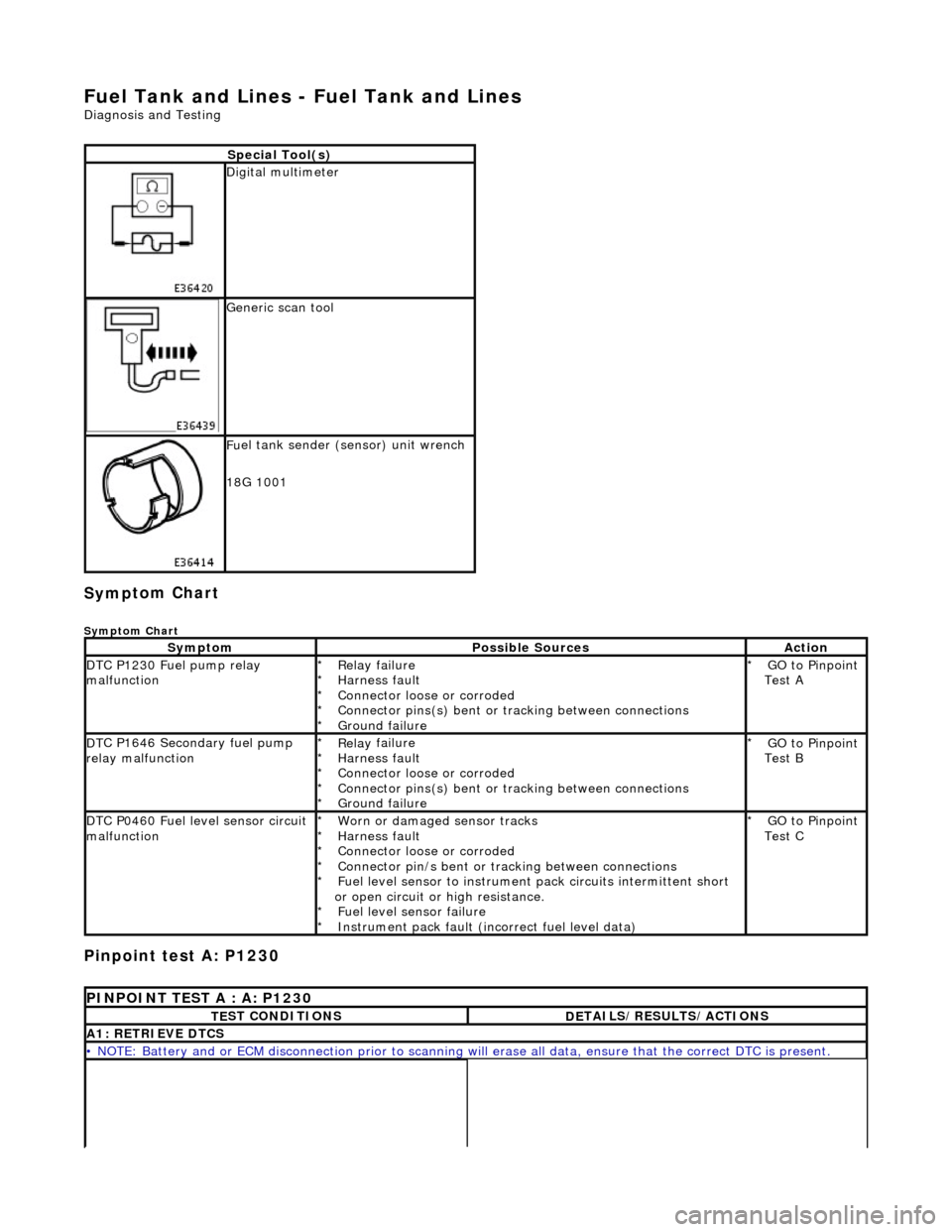
Fuel Tank and Lines - Fuel Tank and Li
nes
D
iagn
osis and Testing
Sym
p
tom Chart
Sy
m
ptom Chart
Pinpoint test A: P1230
S
p
ecial Tool(s)
D
i
gital multimeter
Generi
c scan tool
F
u
el tank sender (sensor) unit wrench
18G 1001
Sy m
ptom
Possib
l
e Sources
Acti
o
n
D
T
C P1230 Fuel pump relay
malfunction
Re lay
failure
Harness fault
Connector loose or corroded
Connector pins(s) bent or tracking between connections
Ground failure
*
*
*
*
*
GO to Pinpoint
Test A
*
D
T
C P1646 Secondary fuel pump
relay malfunction
Re lay
failure
Harness fault
Connector loose or corroded
Connector pins(s) bent or tracking between connections
Ground failure
*
*
*
*
*
GO to Pinpoint
Test B
*
D
T
C P0460 Fuel level sensor circuit
malfunction
Worn
or damaged sensor tracks
Harness fault
Connector loose or corroded
Connector pin/s bent or tracking between connections
Fuel level sensor to instrument pack circui ts intermittent short
or open circuit or high resistance. Fuel level sensor failure
Instrument pack fault (inc orrect fuel level data)
*
*
*
*
*
*
*
GO to Pinpoint
Test C
*
P
INPOINT TES
T A : A: P1230
T
E
ST CONDITIONS
D
E
TAILS/RESULTS/ACTIONS
A1
: RETRIEV
E DTCS
•
NOTE
: Battery and or ECM disconnection prior to scanning wi
ll erase all data, ensure that the correct DTC is present.
Page 1702 of 2490
Measure t
he resistance between relay socket pin 5 and
ground BT020L.
1
I s
the resistance < 10OHM?
Yes GO to A6
No GO to A10
A6: CHECK FUEL
PUMP DRAWN CURRENT
•
NOTE
: With EM013 disconnected this test will cause the pump to operate continuously. Do not exceed 10 sec running.
•
NOTE: Do not replace relay.
Page 1716 of 2490
Measure t
he resistance between relay socket pin 5 and
ground BT020L.
1
I s
the resistance < 10OHM?
Yes GO to B6
No GO to B10
B6: CHECK FUEL
PUMP DRAWN CURRENT
•
NOTE
: With EM013 disconnected this test will cause the pump to operate continuously. Do not exceed 10 sec running.
•
NOTE: Do not replace relay.
Page 1976 of 2490

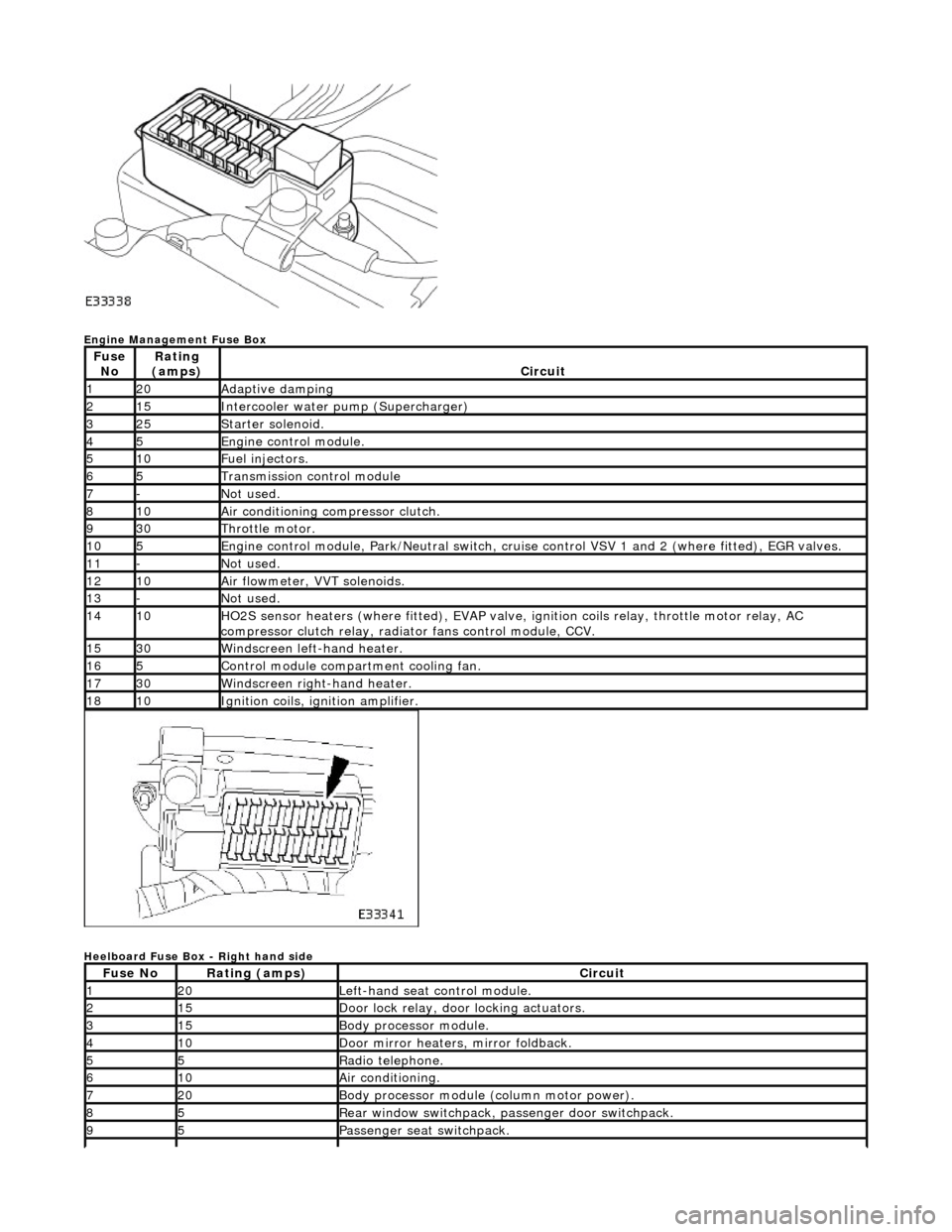
Engine Management Fuse Box
Heelboard Fuse Box - Right hand side
Fuse NoRating
(amps)Circuit
120Adaptive damping
215Intercooler water pump (Supercharger)
325Starter solenoid.
45Engine control module.
510Fuel injectors.
65Transmission control module
7-Not used.
810Air conditioning compressor clutch.
930Throttle motor.
105Engine control module, Park/Neutr al switch, cruise control VSV 1 and 2 (where fitted), EGR valves.
11-Not used.
1210Air flowmeter, VVT solenoids.
13-Not used.
1410HO2S sensor heaters (where fitted ), EVAP valve, ignition coils relay, throttle motor relay, AC
compressor clutch relay, radi ator fans control module, CCV.
1530Windscreen left-hand heater.
165Control module compartment cooling fan.
1730Windscreen right-hand heater.
1810Ignition coils, ignition amplifier.
Fuse NoRating (amps)Circuit
120Left-hand seat control module.
215Door lock relay, door locking actuators.
315Body processor module.
410Door mirror heaters, mirror foldback.
55Radio telephone.
610Air conditioning.
720Body processor module (column motor power).
85Rear window switchpack, passenger door switchpack.
95Passenger seat switchpack.
Page 1978 of 2490

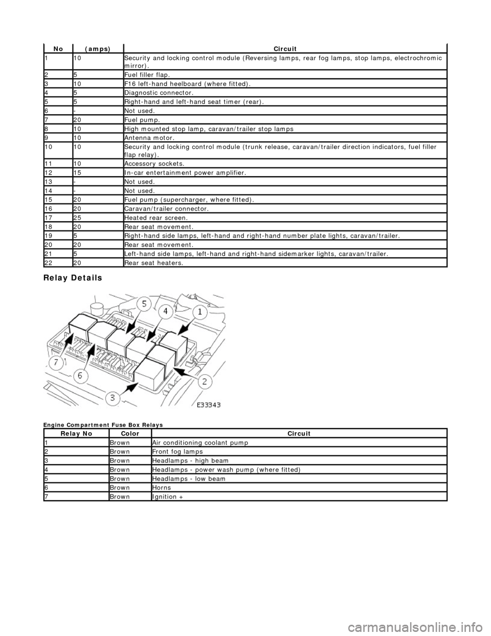
Relay Details
Engine Compartment Fuse Box Relays
No(amps)Circuit
110Security and locking control module (Reversing lamps, rear fog lamps, stop lamps, electrochromic
mirror).
25Fuel filler flap.
310F16 left-hand heelboard (where fitted).
45Diagnostic connector.
55Right-hand and left-han d seat timer (rear).
6-Not used.
720Fuel pump.
810High mounted stop lamp, caravan/trailer stop lamps
910Antenna motor.
1010Security and locking control module (trunk release, caravan/trailer direction indicators, fuel filler
flap relay).
1110Accessory sockets.
1215In-car entertainment power amplifier.
13-Not used.
14-Not used.
1520Fuel pump (supercharger, where fitted).
1620Caravan/trailer connector.
1725Heated rear screen.
1820Rear seat movement.
195Right-hand side lamps, left-h and and right-hand number pl ate lights, caravan/trailer.
2020Rear seat movement.
215Left-hand side lamps, left-hand and right-hand sidemarker lights, caravan/trailer.
2220Rear seat heaters.
Relay NoColorCircuit
1BrownAir conditioning coolant pump
2BrownFront fog lamps
3BrownHeadlamps - high beam
4BrownHeadlamps - power wash pump (where fitted)
5BrownHeadlamps - low beam
6BrownHorns
7BrownIgnition +
Page 1979 of 2490
Engine Management Fuse Box Relay
Engine Compartment - Front Relays
Engine and Transmission Control Module Compartment Relays
Relay NoColorCircuit
1BrownEMS control relay
Relay NoColorCircuit
1BlackWindshield wiper fast/slow
2BlackWindshield wiper on/off
Relay NoColorCircuit
1BlueSC coolant water pump
2BrownFuel injection main
3BrownIgnition coils
4BrownThrottle motor
5BrownStarter solenoid
6BrownAir conditioning compressor clutch
Page 1981 of 2490
Trunk Fuse Box Relays
5VioletDoor mirror fold out (where fitted)
Relay NoColorCircuit
1BrownSecond fuel pump (SC models only)
2BrownRear window defroster
3BrownSide marker, license plate and trailer rear lamps
4BrownFuel pump
5BrownStop lamps (HMSL and trailer only)
6VioletAccessory socket (where fitted)
7VioletFuel filler flap lock
8VioletFuel filler flap unlock
Page:
< prev 1-8 9-16 17-24