1998 JAGUAR X308 stop start
[x] Cancel search: stop startPage 44 of 2490

Electrically Programmable
R
ead-Only memory
EPROM
Ele
c
tronic Secondary Air
Injection
EAIRA p
ump-driven system for providing seco
ndary air using an electric air pump
Engine C
ontrol Module
ECM
End of dashEODR
e
ferring to a vehicle fascia, eg EOD air vent
Engine
C
oolant Level
ECL
Engine
C
oolant
Temperature
ECT
ECT Sen s
or
ECTSTherm
i
stor which provides engine coolant temperature signal to the ECM to
trigger enrichment circuits which increase injector 'on' time for cold start and
warm-up
Engine s
peed
RP
M
Environ m
ental Protection
Agency
EPA
Evaporative EmissionEVAPSy stem designed to prevent fu
el vapor from escaping into the atmosphere.
Typically includes a charcoal filled canister to absorb fuel vapor
Evaporative Emission
Control ValveEVAPP
Exhaust G
as Recirculation
EGRSys
t
em which reduces NOx emissions by adding exhaust gases to the
incoming fuel/air charge
Exhaus t G
as Recirculation
Solenoid Vacuum Valve
EGRS
Exhaus t G
as Recirculation
Temperature Sensor
EGRT Sen s
or
Exhaus
t G
as Recirculation
Valve
EGRV
F
F a
n Control
FCEngine
cooling fan control
F
e
deral Motor Vehicle
Safety Standard (US)
FMV S
S
Fi
gur
e
Fi
g.Illustrati
on reference
Flash
E
lectrically Erasable
Programmable Read-Only
Memory
FEE PR
OM
Flash
E
rasable
Programmable Read-Only
Memory
FEP R
OM
Flywhee
l
Sensor
CKFSSens
or moun
ted so as to be
triggered by each flywheel ring gear tooth to give
an engine speed signal
Fue l
Injectors
FISol
e
noid operated devices that spray a metered quantity of fuel into the inlet
ports
F u
el Pressure Regulator
Control
FP RCControls fuel pressure regu l
ator; used primarily to
give extra fuel at cold
start-up
Fue l
Pump
FP
Fue
l
Pump Monitor
FP
MMonitors operation of fuel pump
Fue l
Pump Relay
FP
R
Fu
el rich/lean
Q
u
alitative evaluation
of air/fuel ratio based on a ratio known as
stoichiometry, or 14.7:1 (Lambda)
F u
ll Scale Deflection
FSDTh
e
maximum indication point on
an analogue meter or gauge
G
Gene
rator
GENRot
a
ting machine which converts mechanical energy into electrical energy
G
r
amme centimeter
gcm
Gramm
e
(force)
gf
Gramm
e
(mass)
g
GroundGNDEle
c
trical conductor used
as a common return for an electrical circuit or
circuits, and with a relative zero potential
H
Hard f a
ult
A
fau
lt currently present in the system
HeadlampHL
Heat
ed Oxygen
Sensor
HO2SElectrically
h
eated oxygen sensor which induces fueling corrections
Hertz (frequency)HzFrequ
e
ncy, one cycle per second
High
Moun
ted Stoplamp
HMSL
Page 318 of 2490

Comp
onent Tests
Bra
k
e Booster
1.
1. Chec k all
hoses and connections. All unused vacuum connectors should be capped. Hoses and their connections
should be correctly secured and in good condition with no holes and no collapsed areas. Inspect the valve on the
brake booster for damage.
2. 2. Check the hydraulic brake system for leaks or low fluid.
3. 3. With the transmission in PARK, stop the engine and apply the parking brake. Pump the brake pedal several times
to exhaust all vacuum in the system.
4. 4. With the engine switched off and all vacuum in the system exhausted, appl y the brake pedal and hold it down.
Start the engine. If the vacuum system is operating, the brake pedal will tend to move downward under constant
foot pressure. If no motion is felt, the vacuum booster system is not functioning.
5. 5. Remove the vacuum hose from the brake booster. Manifold vacuum should be available at the brake booster end
of the hose with the engine at idle speed and the transm ission in PARK or NEUTRAL. Make sure that all unused
vacuum outlets are correctly capped, hose connectors are correctly secured and vacuum hoses are in good
condition. When it is established that manifold vacuum is available to the brake booster, connect the vacuum hose
to the brake booster and repeat Step 3. If no downward movement of the brake pedal is felt, install a new brake
booster.
6. 6. Operate the engine for a minimum of 10 seconds at a fast idle. Stop the engine and allow the vehicle to stand for
10 minutes. Then, apply th e brake pedal with approximately 89 N ( 20lb) of force. The pedal feel (brake
application) should be the same as that noted with the engine running. If the brake pedal feels hard (no power
assist), install a new valve and then re peat the test. If the brake pedal still feels hard, in stall a new brake booster.
If the brake pedal movement feels spongy, bleed the brak e system. For additional information, refer to General
Procedures in this section.
Bra k
e Master Cylinder
Usual
l
y, the first and strongest
indicator of anything wrong in the brake syst em is a feeling through the brake pedal. In
diagnosing the condition of the brake master cylinder, check pedal feel as evidence of a brake concern. Check for brake
warning lamp illumination and the brake fluid le vel in the brake master cylinder reservoir.
Normal Conditio
ns
The fo
llowing conditions are considered norm
al and are not indications that the brake master cylinder is in need of repair.
New bra
ke systems are designed to produc
e a pedal effort that is not as hard as in the past. Complaints of light
pedal efforts should be compared to the pedal effort s of another vehicle of the same model and year.
The fl
uid level will fall with brake pad wear.
Abnormal Conditions
•
NOTE: Prior to carrying out any diag
nosis, make sure the brake system warning indicator is functional.
Changes in the brake pedal feel or brake pedal travel are in dicators that something could be wrong in the brake system. The
diagnostic procedure and techniques use brake pedal feel, warning indicator illu mination and low brake fluid level as
indicators to diagnosing brake system co ncerns. The following conditions are cons idered abnormal and indicate that the
brake master cylinder is in need of repair:
Brake ped a
l goes down fast. Th
is could be caused by an ex ternal or internal leak.
Brake pedal goes down slowly
. This could be
caused by an internal or external leak.
Brak
e pedal is low or feels spongy. This condition may be ca
used by no fluid in the brake master cylinder, reservoir
Page 432 of 2490

It is a reciprocating two
-circuit pu
mp in which one brake circuit is as signed to each pump circuit.
It supplies th
e fluid pressure and vo
lume to supply the brake circuits under ABS and Traction control.
The pump is driven by an electri
c motor, with the pump
housing incorporating two lo w pressure accumulators and
damping chambers for each brake circuit.
The ac cu
mulator stores the pressure and smooths out the output pu
lses from the pump.
ABS Warning Lamp
The sys
tem will be set in a fail-safe mode if a problem is de
tected; a warning lamp on the instrument panel will notify the
driver there is a problem.
Anti-Lock Braking Sy
stem (ABS)
The AB
S components are combined with
an hydraulic booster and a tandem master cylinder to provide a two circuit braking
system. The system comprises, four wheel speed sensor s, a brake control modulator and an ABS warning lamp.
Should a wheel start to lock-up during braking a signal tr ansmitted from the wheel speed sensor to the brake control
modulator will start the hydraulic pump. The brake control modula tor will close the input valve of the line connected to the
locked-wheel to stop any increase in fluid pressure to the br ake caliper. If this fails to prevent the wheel locking, the
pressure in the caliper will be decreased by opening the return valve until th e wheel starts accelerating again. The fluid
pressure from the return va lve is directed into the low pressure accumulator, housed in the pump.
From the low pressure accumulator, fl uid is pumped through the damping cham ber to the brake master cylinder. The
pressure to the brake caliper will then be increased in small steps to maintain maximum adhesion between the tire and road
surface. This is achieved by closing the return valve, and opening the input valve and using the hydraulic pump to increase
the pressure.
Although the system senses all four wheels independently, the rear wheels are regulated as a pair. If a sensor on a rear
wheel detects a wheel decelerating rapidly, then the fluid pressure to both wheels is reduced. The fluid pressure is then
dictated by the wheel having the lowe st adhesion with the road surface.
The ABS system will be set in a fail-safe mode if a problem is detected; a warn ing lamp on the instrument panel will notify
the driver there is a problem. The brake system will still operate conventionally and with the same standard of performance
as a vehicle not equipped with ABS.
Automa tic Stability Control (ASC)
Th
e ASC utilizes the ABS sensing arrangement to provide the maximum traction force to propel the vehicle.
The ASC is switched on when the engine is started. The system can be switched off by pressing the 'ASC OFF' (the switched
is marked 'TRAC OFF' on vehicles fitted with traction control). The switch, which is situated in the center console switchpack,
lights up to warn that the system is sw itched off. An 'ASC' amber warning light flashes on the instrument panel when the
system detects a spinning wheel.
The ASC system uses engine intervention to reduce the torque delivered to the drive wheels to prevent them spinning.
Engine torque is re duced in three ways:
The
throttle is moved towards the closed position.
The ignition is retarded. F
u
el is cut-off at the cylinder injectors.
Wheel spin is detected by the wheel sp eed sensors and communicated to the AB S/TCCM. The ABS/TCCM uses information
from the controller area network (CAN) to calculate the torque that the engine should produce to stop the wheel spinning.
Torque reductions are then requested from the engine control module (ECM ) through the CAN. The throttle is then
positioned to provide the target torque, which has been calculated to prevent wheel spin. During the transient phase of
torque reduction the fuel is cut-off and th e ignition retarded Both the fuel cut-off an d ignition retard will be restored to
normal when the throttle is set to its new position.
The ASC uses a brake control modulator with six solenoid va lves: three normally open inlet valves and three normally
Page 1022 of 2490
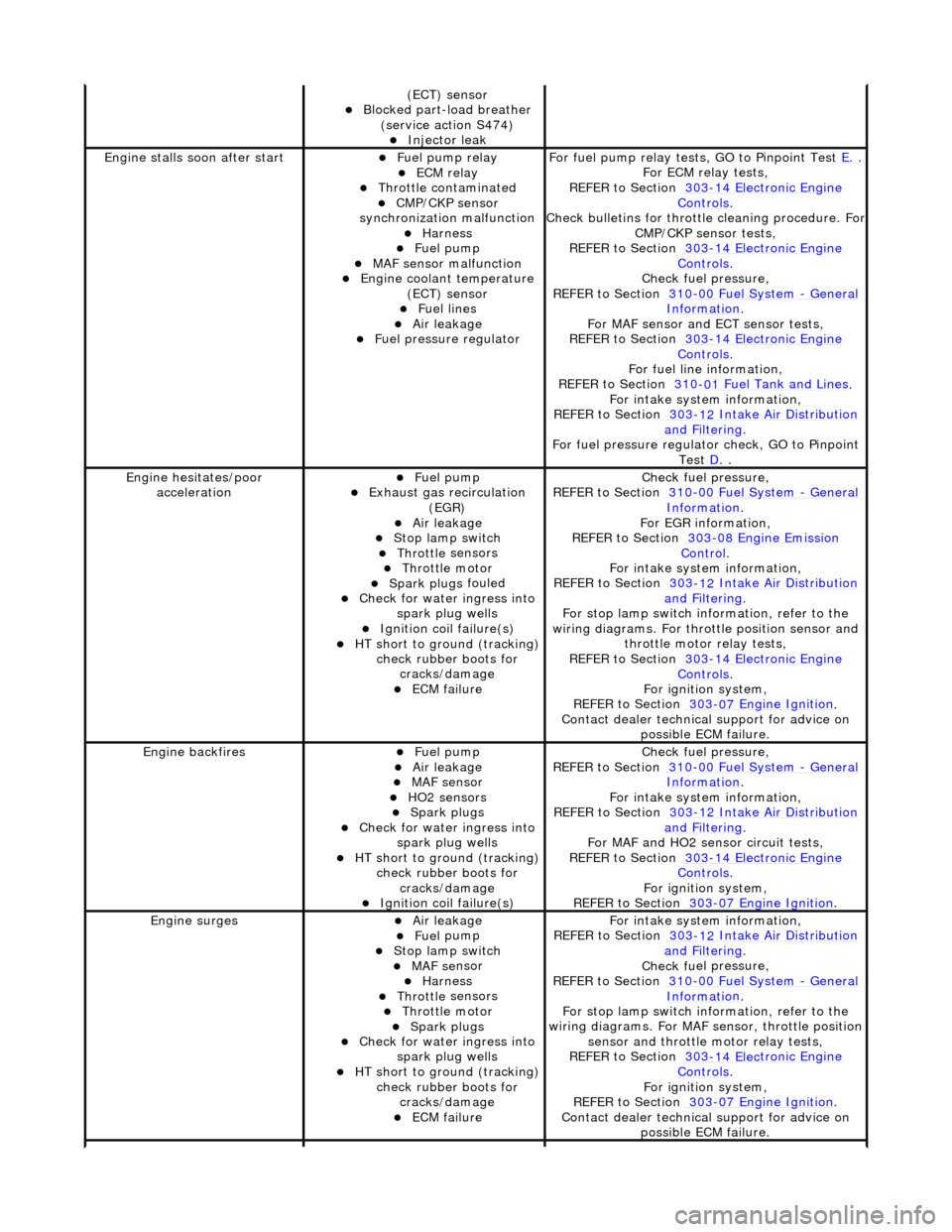
(ECT) se
nsor
Blocked part-load breather
(s
ervice action S474)
Injec
t
or leak
Engine stalls
soon
after start
F
u
el pump relay
ECM relay Thr
o
ttle contaminated
CMP/CKP sen
s
or
synchronization malfunction
Harness Fuel
pump
MAF
s
ensor malfunction
Engine coolan
t
temperature
(ECT) sensor
Fue l
lines
Air leakage Fu
el pressure regulator
F
o
r fuel pump relay tests,
GO to Pinpoint Test E.
.
F or ECM
relay tests,
REFER to Section 303
-14 Elec tronic En
gine
Controls.
Check bull etins for throttl
e cleaning procedure. For
CMP/CKP sensor tests,
REFER to Section 303
-14 Elec tronic En
gine
Controls.
Chec k fu
el pressure,
REFER to Section 310
-00 Fu
el System
- Ge
n
eral
Informati
o
n
.
F or MAF sensor and
ECT sensor tests,
REFER to Section 303
-14 Electronic En
gine
Controls.
For fuel l
ine information,
REFER to Section 310
-01
Fuel Tank and Lines
.
F or i
ntake system information,
REFER to Section 303
-1 2
Intake Air Distribution
and F
ilt
ering
.
F o
r fuel pressure regulato
r check, GO to Pinpoint
Test D.
.
Engine h e
sitates/poor
acceleration
Fue l
pump
Exhaus
t gas
recirculation
(EGR)
Air leakage Stop lamp swi t
ch
Throttl
e
sensors
Throttl
e
motor
Spark plugs
fouled
Check f
o
r water ingress into
spark plug wells
Ignition coil fail
ure(s)
HT sho
rt to ground (tracking)
check rubber
boots for
cracks/damage
ECM failu r
e
Chec
k fu
el pressure,
REFER to Section 310
-00 Fu
el System
- Ge
n
eral
Informati
o
n
.
F o
r EGR information,
REFER to Section 303
-08 En gin
e Emission
Control.
F or i
ntake system information,
REFER to Section 303
-1 2
Intake Air Distribution
and F
ilt
ering
.
F or stop l
amp switch in
formation, refer to the
wiring diagrams. For throttle position sensor and throttle motor relay tests,
REFER to Section 303
-14 Elec tronic En
gine
Controls.
For ign i
tion system,
REFER to Section 303
-07 En
gine Ignition
.
Contact dealer techn i
cal
support for advice on
possible ECM failure.
Engine ba ckfiresFuel
pump
Air leakage MAF s
e
nsor
HO2 sensors Spark plugs
Check fo
r water ingress into
spark plug wells
HT short to ground (tracking) check rubber
boots for
cracks/damage
Ignition coil fail
ure(s)
Chec
k fu
el pressure,
REFER to Section 310
-00 Fu
el System
- Ge
n
eral
Informati
o
n
.
F or i
ntake system information,
REFER to Section 303
-1 2
Intake Air Distribution
and F
ilt
ering
.
For MAF and HO2
sensor circuit tests,
REFER to Section 303
-14 Electronic En
gine
Controls.
For igni
tion system,
REFER to Section 303
-07 En
gine Ignition
.
Engine
s
urges
Air leakage Fue
l
pump
Stop lamp swi
t
ch
MAF s
e
nsor
Harness Throttl
e
sensors
Throttl
e
motor
Spark plugs
Check fo
r water ingress into
spark plug wells
HT sho rt to ground (tracking)
check rubber
boots for
cracks/damage
ECM failu r
e
F
or i
ntake system information,
REFER to Section 303
-1 2
Intake Air Distribution
and F
ilt
ering
.
Chec k fu
el pressure,
REFER to Section 310
-00 Fu
el System
- Gen
e
ral
Informati
o
n
.
F or stop l
amp switch in
formation, refer to the
wiring diagrams. For MAF se nsor, throttle position
sensor and throttle motor relay tests,
REFER to Section 303
-14 Elec tronic En
gine
Controls.
For ign i
tion system,
REFER to Section 303
-07 En
gine Ignition
.
Contact dealer techn i
cal
support for advice on
possible ECM failure.
Page 1270 of 2490
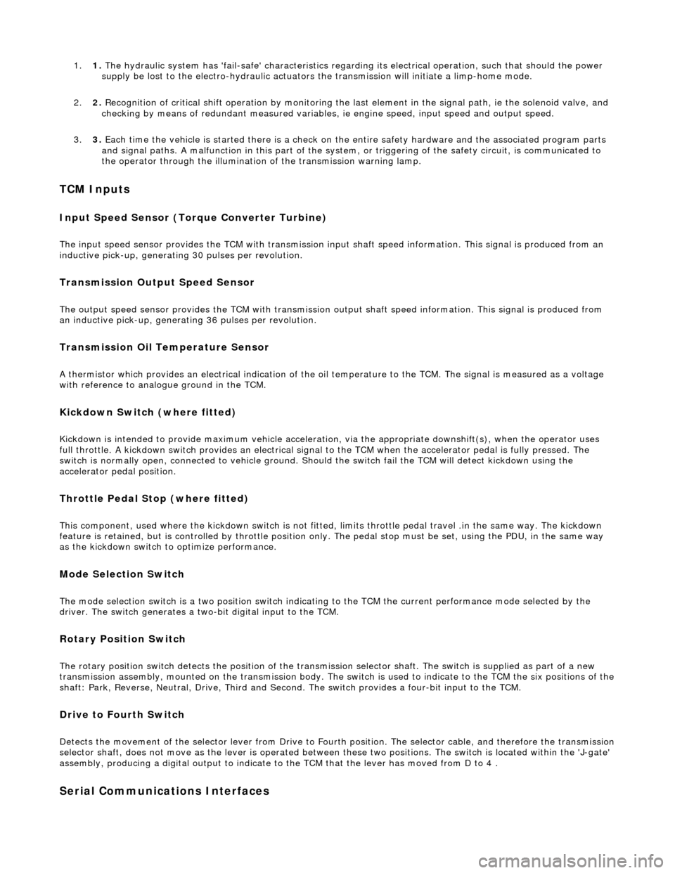
1.1. The hydraulic system has 'fail-safe' characteristics regardin g its electrical operation, such that should the power
supply be lost to the electro-hydraulic actuators the transmission will initiate a limp-home mode.
2. 2. Recognition of critical shift operation by monitoring the last element in the signal path, ie the solenoid valve, and
checking by means of redundant me asured variables, ie engine speed, input speed and output speed.
3. 3. Each time the vehicle is started there is a check on the entire safety hardware and the associated program parts
and signal paths. A malfunction in this part of the system, or triggering of the safety circuit, is communicated to
the operator through the illumination of the transmission warning lamp.
TCM Inputs
Input Speed Sensor (Torque Converter Turbine)
The input speed sensor provides the TCM with transmission inpu t shaft speed information. This signal is produced from an
inductive pick-up, generating 30 pulses per revolution.
Transmission Output Speed Sensor
The output speed sensor provides the TCM with transmission ou tput shaft speed information. This signal is produced from
an inductive pick-up, generati ng 36 pulses per revolution.
Transmission Oil Temperature Sensor
A thermistor which provides an electrical indication of the oi l temperature to the TCM. The signal is measured as a voltage
with reference to analog ue ground in the TCM.
Kickdown Switch (where fitted)
Kickdown is intended to provide maximum vehicle acceleration , via the appropriate downshift(s), when the operator uses
full throttle. A kickdown switch provides an electrical signal to the TCM wh en the accelerator pedal is fully pressed. The
switch is normally open, connected to vehicle ground. Should the switch fail the TCM will detect kickdown using the
accelerator pedal position.
Throttle Pedal Stop (where fitted)
This component, used where the kickdown switch is not fitted, limits throttle pedal travel .in the same way. The kickdown
feature is retained, but is controlled by throttle position only. The pedal stop must be set, using the PDU, in the same way
as the kickdown switch to optimize performance.
Mode Selection Switch
The mode selection switch is a two position switch indicati ng to the TCM the current performance mode selected by the
driver. The switch generates a tw o-bit digital input to the TCM.
Rotary Position Switch
The rotary position switch detects the position of the transmis sion selector shaft. The switch is supplied as part of a new
transmission assembly, mounted on the transmission body. The swit ch is used to indicate to the TCM the six positions of the shaft: Park, Reverse, Neutral, Drive, Third and Second. The switch provides a four-bit input to the TCM.
Drive to Fourth Switch
Detects the movement of the selector lever from Drive to Fourth position. The selector cable, and therefore the transmission selector shaft, does not move as the lever is operated between these two positions. The switch is located within the 'J-gate'
assembly, producing a digital output to indicate to the TCM that the lever has moved from D to 4 .
Serial Communications Interfaces
Page 1295 of 2490
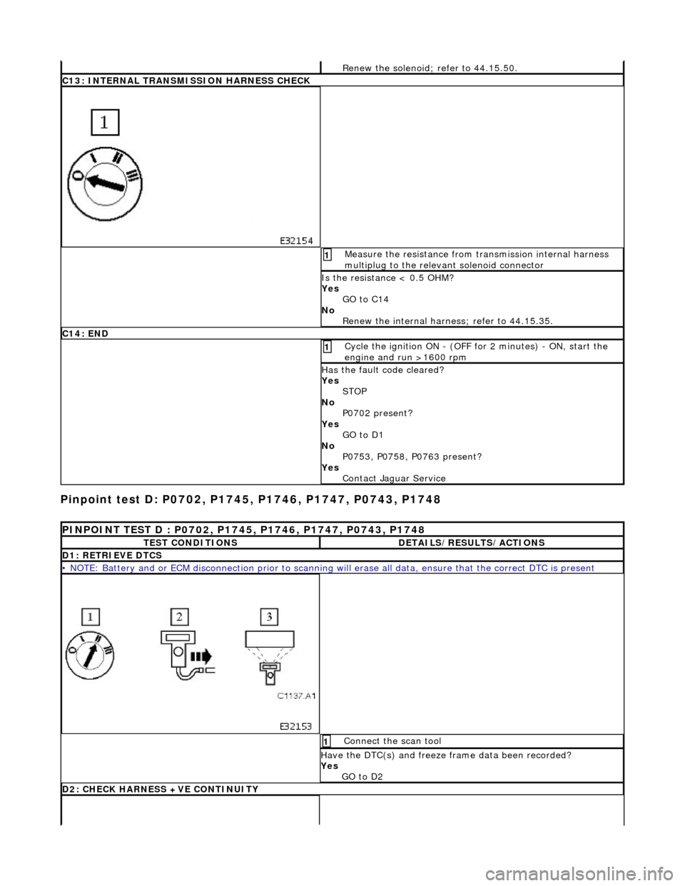
Pinpoint test D: P0702, P1745, P1746, P1747, P0743, P1748
Renew the solenoid; refer to 44.15.50.
C13: INTERNAL TRANSMISSION HARNESS CHECK
Measure the resistance from transmission internal harness
multiplug to the relevant solenoid connector 1
Is the resistance < 0.5 OHM?
Yes GO to C14
No Renew the internal harnes s; refer to 44.15.35.
C14: END
Cycle the ignition ON - (OFF for 2 minutes) - ON, start the
engine and run >1600 rpm 1
Has the fault code cleared?
Yes
STOP
No P0702 present?
Yes GO to D1
No P0753, P0758, P0763 present?
Yes Contact Jaguar Service
PINPOINT TEST D : P0702, P1745, P1746, P1747, P0743, P1748
TEST CONDITIONSDETAILS/RESULTS/ACTIONS
D1: RETRIEVE DTCS
• NOTE: Battery and or ECM disconnection prior to scanning wi ll erase all data, ensure that the correct DTC is present
Connect the scan tool 1
Have the DTC(s) and freeze frame data been recorded?
Yes GO to D2
D2: CHECK HARNESS +VE CONTINUITY
Page 1306 of 2490
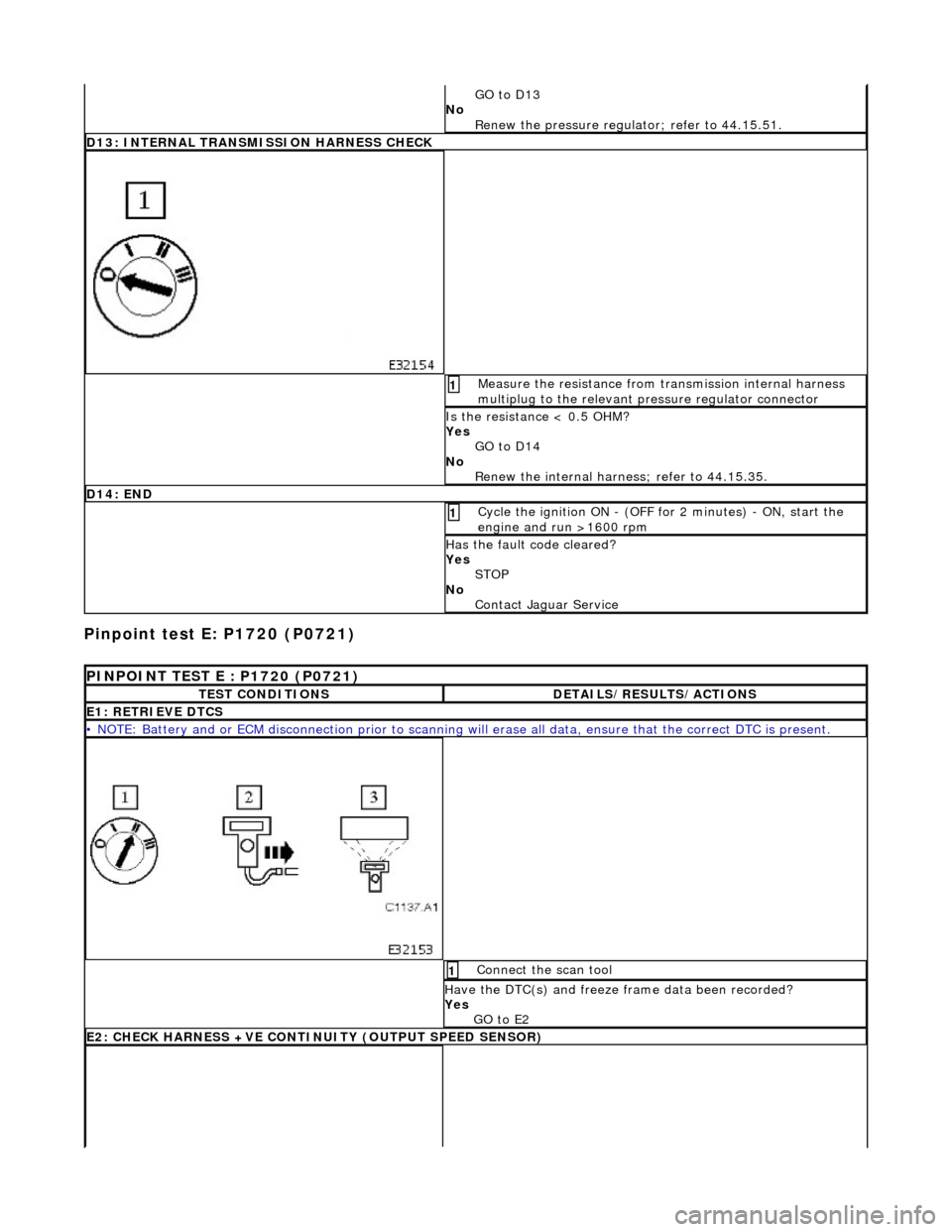
Pinpoint test E: P1720 (P0721)
GO to D13
No Renew the pressure regulator; refer to 44.15.51.
D13: INTERNAL TRANSMISSION HARNESS CHECK
Measure the resistance from transmission internal harness
multiplug to the relevant pr essure regulator connector 1
Is the resistance < 0.5 OHM?
Yes
GO to D14
No Renew the internal harnes s; refer to 44.15.35.
D14: END
Cycle the ignition ON - (OFF for 2 minutes) - ON, start the
engine and run >1600 rpm 1
Has the fault code cleared?
Yes
STOP
No Contact Jaguar Service
PINPOINT TEST E : P1720 (P0721)
TEST CONDITIONSDETAILS/RESULTS/ACTIONS
E1: RETRIEVE DTCS
• NOTE: Battery and or ECM disconnection prior to scanning wi ll erase all data, ensure that the correct DTC is present.
Connect the scan tool 1
Have the DTC(s) and freeze frame data been recorded?
Yes GO to E2
E2: CHECK HARNESS +VE CONTIN UITY (OUTPUT SPEED SENSOR)
Page 1412 of 2490
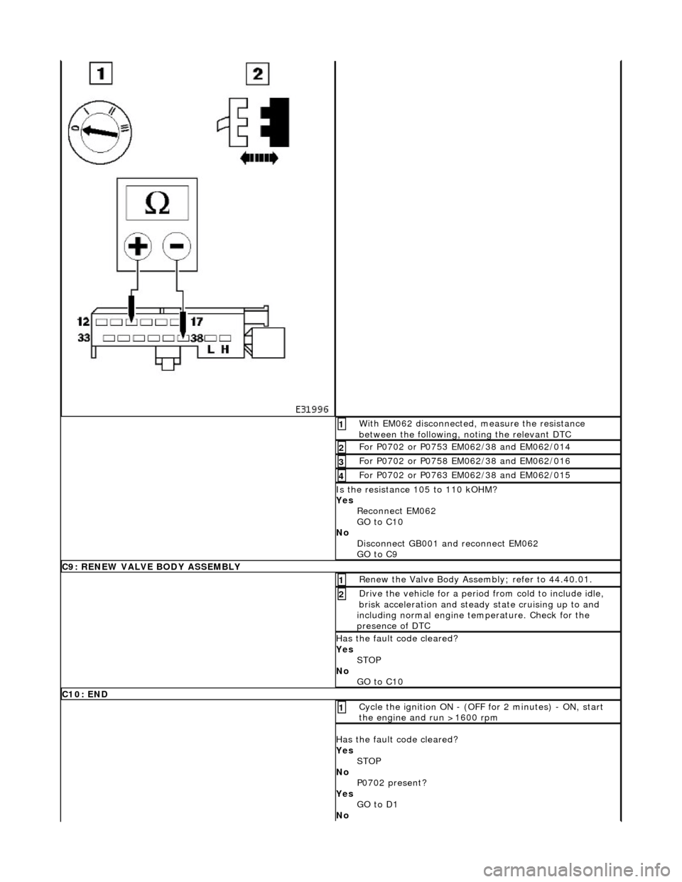
With EM062 disconnected, measure the resistance
between the following, noting the relevant DTC 1
For P0702 or P0753 EM062/38 and EM062/014 2
For P0702 or P0758 EM062/38 and EM062/016 3
For P0702 or P0763 EM062/38 and EM062/015 4
Is the resistance 105 to 110 kOHM?
Yes Reconnect EM062
GO to C10
No Disconnect GB001 and reconnect EM062
GO to C9
C9: RENEW VALVE BODY ASSEMBLY
Renew the Valve Body Assembly; refer to 44.40.01. 1
Drive the vehicle for a period from cold to include idle,
brisk acceleration and steady state cruising up to and
including normal engine temperature. Check for the
presence of DTC 2
Has the fault code cleared?
Yes STOP
No GO to C10
C10: END
Cycle the ignition ON - (OFF for 2 minutes) - ON, start
the engine and run >1600 rpm 1
Has the fault code cleared?
Yes STOP
No P0702 present?
Yes GO to D1
No