Page 2219 of 2490

Instrument Panel and Console - Instrument Panel and Instrument Panel
Console
Description and Operation
Fascia
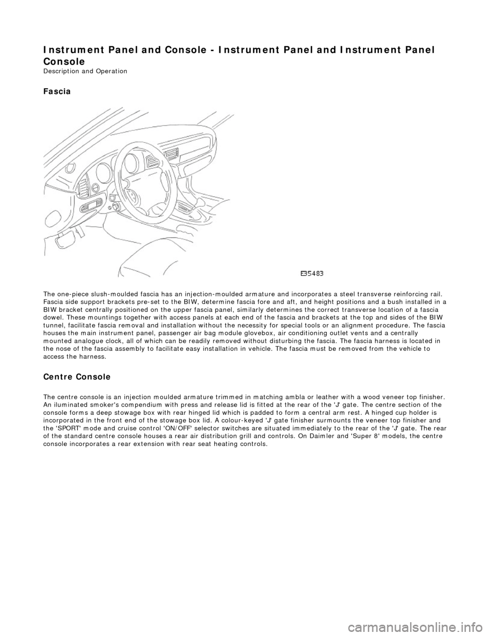
The one-piece slush-moulded fascia has an injection-moulded ar mature and incorporates a steel transverse reinforcing rail.
Fascia side support brackets pre-set to th e BIW, determine fascia fore and aft, and height position s and a bush installed in a
BIW bracket centrally positioned on the upper fascia panel, similarly determines the correct transverse location of a fascia
dowel. These mountings together with access panels at each en d of the fascia and brackets at the top and sides of the BIW
tunnel, facilitate fascia removal and instal lation without the necessity for special tools or an alignment procedure. The fasci a
houses the main instrument panel, pass enger air bag module glovebox, air conditioning outlet vents and a centrally
mounted analogue clock, all of which can be readily removed wi thout disturbing the fascia. The fascia harness is located in
the nose of the fascia assembly to facilitate easy installati on in vehicle. The fascia must be removed from the vehicle to
access the harness.
Centre Console
The centre console is an injection moulded armature trimmed in matching ambla or leather with a wood veneer top finisher.
An iluminated smoker's compendium with pr ess and release lid is fitted at the rear of the 'J' gate. The centre section of the
console forms a deep stowage box with rear hinged lid which is padded to form a central arm rest. A hinged cup holder is
incorporated in the front end of the stowage box lid. A colour-keyed 'J' gate finisher surmounts the veneer top finisher and
the 'SPORT' mode and cruise control 'ON/OFF' selector switches are situated immediately to the rear of the 'J' gate. The rear
of the standard centre console houses a re ar air distribution grill and controls. On Daimler and 'Super 8' models, the centre
console incorporates a rear extensio n with rear seat heating controls.
Page 2225 of 2490

Installation
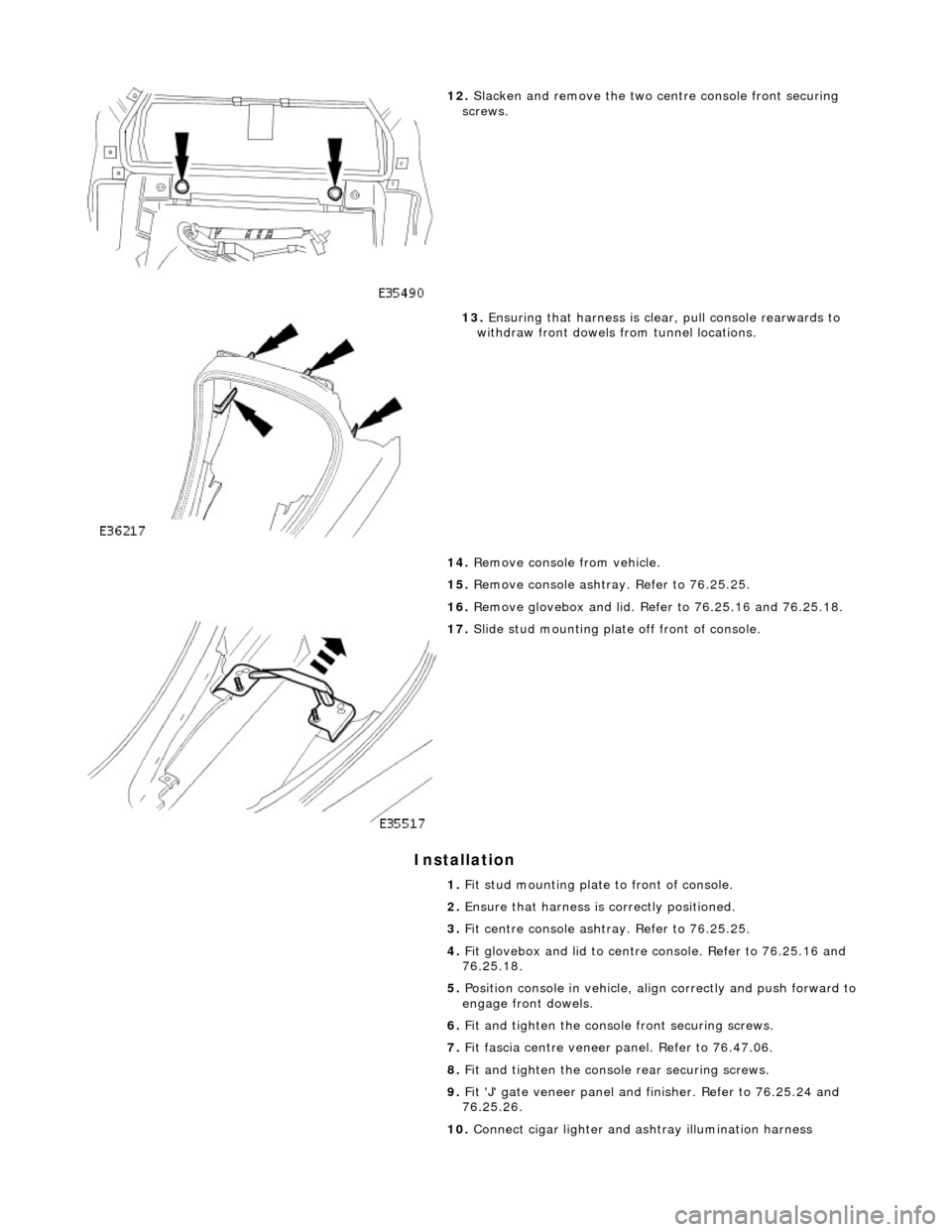
12. Slacken and remove the two ce ntre console front securing
screws.
13. Ensuring that harness is clea r, pull console rearwards to
withdraw front dowels from tunnel locations.
14. Remove console from vehicle.
15. Remove console ashtray. Refer to 76.25.25.
16. Remove glovebox and lid. Refer to 76.25.16 and 76.25.18.
17. Slide stud mounting plate off front of console.
1. Fit stud mounting plate to front of console.
2. Ensure that harness is correctly positioned.
3. Fit centre console ashtray. Refer to 76.25.25.
4. Fit glovebox and lid to centre console. Refer to 76.25.16 and
76.25.18.
5. Position console in vehicle, align correctly and push forward to
engage front dowels.
6. Fit and tighten the consol e front securing screws.
7. Fit fascia centre veneer panel. Refer to 76.47.06.
8. Fit and tighten the console rear securing screws.
9. Fit 'J' gate veneer panel and finisher. Refer to 76.25.24 and
76.25.26.
10. Connect cigar lighter and as htray illumination harness
Page 2232 of 2490
Instrument Panel and Console - Floor Console Stowage Compartment
Removal and Installation
Removal
Installation
1.
Open console gl ove box lid.
2. Slacken and remove the glove box lid stay securing screw and
remove lid stay.
3. Slacken and remove glove box latch securing screws and
remove latch assembly.
4. Slacken and remove glovebox liner rear securing screws.
5. Remove glovebox liner from vehicle.
1. Position glovebox liner in console.
2. Fit and tighten liner rear securing screws.
3. Position latch assembly on line r and fit and tighten securing
screws.
4. Fit and tighten check arm to lid securing screw.
5. Position lid to stay and fit and tighten securing screw.
6. Close glovebox lid.
Page 2233 of 2490
Instrument Panel and Console - Floor Console Stowage Compartment Lid
Removal and Installation
Removal
1. Open glovebox lid.
2. Slacken and remove lid stay se curing screw and remove stay from lid.
3. Slacken and remove glovebox latch securing screws and
remove latch from glovebox.
4. Slacken and remove glovebox li ner rear securing screws and
remove liner for access.
5. Slacken and remove remaining gl ovebox hinge securing screw.
Page 2234 of 2490
Installation
6.
Slacken and remove screws securing hinge to lid and remove
hinge.
1. Position hinge on console lid and fit and tighten securing
screws.
2. Position glovebox lid on cent re comsole and fit and tighten
securing screw.
3. Fully seat liner in centre co nsole and fit and tighten rear
securing screws.
4. Fit glovebox latch to liner and fit and tighten securing screws.
5. Position glovebox to lid stay, fi t and tighten securing screw and
close glovebox lid.
Page 2235 of 2490
Instrument Panel and Console - Glove Compartment
Removal and Installation
Removal
Installation
1.
Open glovebox.
2. Supporting the glovebox, slac ken and remove the four top
securing screws.
3. Slacken and remove the two glovebox lower outer securing
screws.
4. Withdraw glovebox for access and disconnect the two
illumination harness connectors.
5. Remove glovebox from vehicle.
1. Position glovebox for access and connect illumination harness.
2. Position and fully seat glovebox.
3. Fit but do not tighten the lower securing screws.
4. Fit and fully tighten the upper securing screws.
5. Close glovebox lid.
6. Fully tighten the lower securing screws.
Page 2236 of 2490
Instrument Panel and Console - Glove Compartment Lid
Removal and Installation
Removal
Installation
1.
Remove glovebox. Refer to 76.52.03.
2. Open glovebox lid and lift barbed hook to release damper
cord loop from lid..
3. Slacken and remove the two lid hinge securing nuts.
4. Remove glovebox lid.
1. Fit glovebox lid to liner.
2. Position lid on hinges and fi t but do not tighten securing
screws.
3. Fit damper cord loop to lid.
4. Position and fit glovebox. Refer to 76.52.03.
5. Adjust lid position to achieve satisfactory all-round clearance
and catch operation.
6. Fully tighten hinge securing screws.
Page 2237 of 2490
Instrument Panel and Console - Glove Compartment Lid Damper
Removal and Installation
Removal
Installation
1.
remove glovebox assembly. Refer to 76.52.03.
2. Disconnect glovebox damper cord end loop from damper and
route cord through the liner guide.
3. Slacken and remove the two damp er securing nuts and remove damper from liner.
1. Position damper on liner
2. Fit and tighten damper securing nuts.
3. Route damper cord through liner guide and connect end loop to
damper.