1998 JAGUAR X308 ad blue
[x] Cancel search: ad bluePage 1383 of 2490
Automatic Transmission/Transaxle - 4.0L NA V8 - AJ27/3.2L NA V8 - AJ26
- Transmission
Installation
Installation
Special Tool(s)
Engine support
303-021
Engine lifting brackets
303-536
1. Clean all mating faces and relevant parts.
2. Apply lubricant, Molycote or equivalent, to the spigot of the
torque converter.
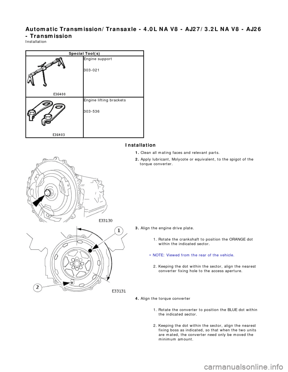
3. Align the engine drive plate.
1. Rotate the crankshaft to position the ORANGE dot
within the indicated sector.
• NOTE: Viewed from the rear of the vehicle.
2. Keeping the dot within the sector, align the nearest converter fixing hole to the access aperture.
4. Align the torque converter
1. Rotate the converter to position the BLUE dot within the indicated sector.
2. Keeping the dot within the sector, align the nearest fixing boss as indicated, so that when the two units
are mated, the converter need only be moved the
minimum amount.
Page 1762 of 2490
Climate Control System - General Infor
mation - Air Conditioning (A/C)
System Recovery, Evacuation and Charging
Gen e
ral Procedures
Recover / Reclaim
Ev
acuation
Charging
1.
CAUTIO
N: Read the procedures and instructions supplied
by the manufacturer of the air co nditioning service center before
commencing any process requiring the handling of refrigerant. In
addition to the manufacturer's in formation, observe all safety
precautions and advice deta iled in this section.
Disconnect battery ground lead; refer to 86.15.19.
2. Remove passenger side fi
rewall cover.
3. Remove driver side firewall cover.
4. Remove engine compar tment rear cover.
5. Re
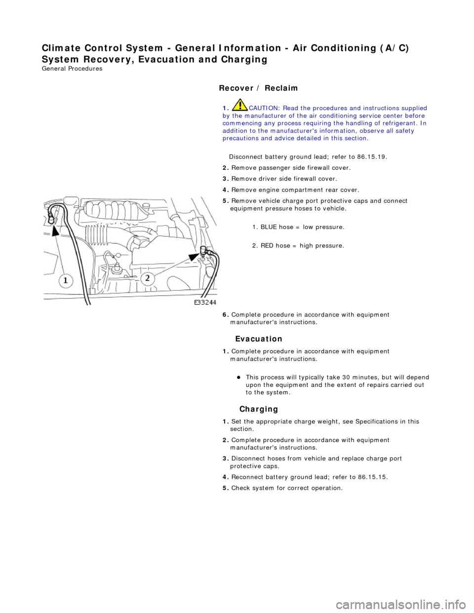
move vehicle charge port
protective caps and connect
equipment pressure hoses to vehicle.
1. BLUE hose = low pressure.
2. RED hose = high pressure.
6. Complete procedure in ac cordance with equipment
manufacturer's instructions.
1. Complete procedure in ac cordance with equipment
manufacturer's instructions.
This proc
ess will typically ta
ke 30 minutes, but will depend
upon the equipment and the ex tent of repairs carried out
to the system.
1. Set the appropriate charge weight, see Specifications in this
section.
2. Complete procedure in ac cordance with equipment
manufacturer's instructions.
3. Disconnect hoses from vehicle and replace charge port
protective caps.
4. Reconnect battery ground lead; refer to 86.15.15.
5. Check system for correct operation.
Page 1764 of 2490
Clima
te Control System - General Inform
ation - Manifold Gauge Set Connection
Ge
neral Procedures
Mani
fol
d.
Low Side Pressure Gauge.
High Side Pressure Gauge.
1.
The 'ma
nifold gauge set' is a most important tool for tracing faults and
system efficiency assessment. The relationship between HIGH and LOW
pressures and their correlation to AMBIENT and EVAPORATOR
temperatures must be compared to determine system status (see
Pressure / Temperature graphs).
Because of the heavy reliance upon this piece of equipment for service
diagnosis, ensure that the gauges are calibrated regularly and the
equipment is treated with care.
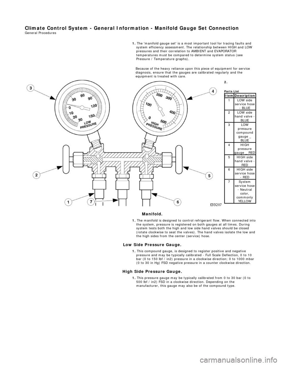
2.
Parts
List
ItemDescri
ption1LOW side
serv
ice hose
- BLUE
2LOW side
ha
nd valve -
BL
UE3LOW
pres
sure
compound
gauge _ BLUE
4HI GH
pressure
gauge _ RED
5HI GH
side
hand valve -
RED6HI GH
side
service hose
- RED
7Sys t
em
service hose
- Neutral color,
commonly YELLOW
1. The manifold is designed to control refrigerant flow. When connected into
the system, pressure is registered on both gauges at all times. During
system tests both the high and low side hand valves should be closed
(rotate clockwise to seat the valves). The hand valves isolate the low and
the high sides from the center (service) hose.
1. This compound gauge, is designed to register positive and negative
pressure and may be typically calibrate d - Full Scale Deflection, 0 to 10
bar (0 to 150 lbf / in2) pressure in a clockwise direction; 0 to 1000 mbar
(0 to 30 in Hg) FSD negative pressu re in a counter clockwise direction.
1. This pressure gauge may be typically calibrated from 0 to 30 bar (0 to
500 lbf / in2) FSD in a clockwise direction. Depending on the
manufacturer, this gauge may also be of the compound type.
Page 1824 of 2490
External temperature < -10 °C Vehicle speed > 65 km / h The first two conditions exist > 2 minutes. Engine speed > 50 revs / min
14. 14. Heated Backlight (R)
Pressing the heated backlight button will simultaneously energize the heater elements for timed cycles of;
21 minutes backlight 11 minutes exterior mirrors
Pressing the button again within the 21 minute timer will cancel the request.
If the engine is stalled, or the ignition switched OFF, the backlight and door mirror timers will be cleared, resulting in both
functions being switched off.
• NOTE: Both the backlight and door mirrors may be activated with the climate control system OFF, but the engine must be
running.
15. 15. Temperature Decrease
Pressing this button (BLUE symbol) decreases the interior temperature setting in 1° increments. Should the button be
pressed when the setting temperature is below the lower automatic control temperature limit, the display will indicate 'LO'.
16. 16. Temperature Increase
Pressing this button (RED symbol) will raise the temperature setting in 1° increments Should the button be pressed when
the setting temperature is above the upper automatic control temperature limit, the display will indicate 'HI'.
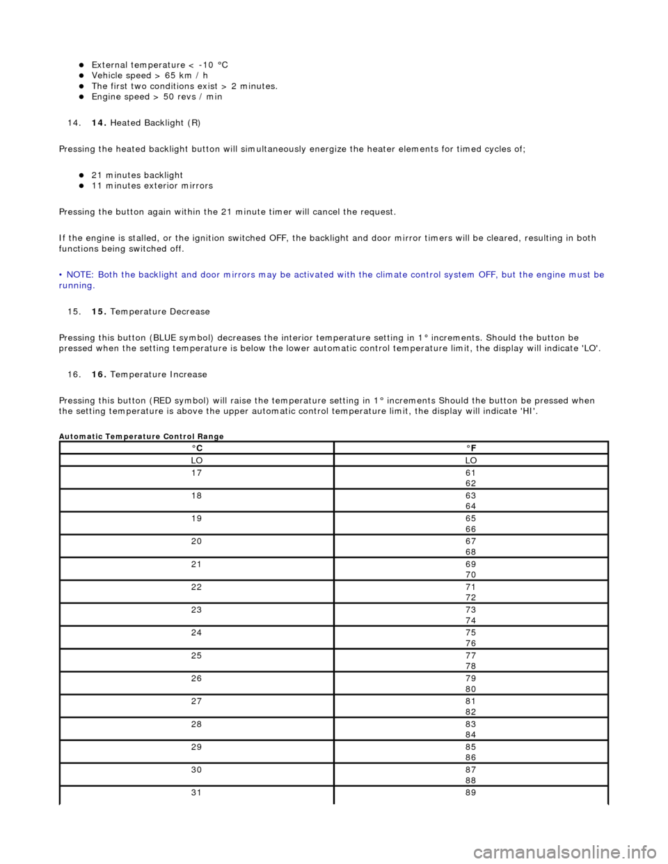
Automatic Temperature Control Range
°C°F
LOLO
1761
62
1863
64
1965
66
2067
68
2169
70
2271
72
2373
74
2475
76
2577
78
2679
80
2781
82
2883
84
2985
86
3087
88
3189
Page 1836 of 2490
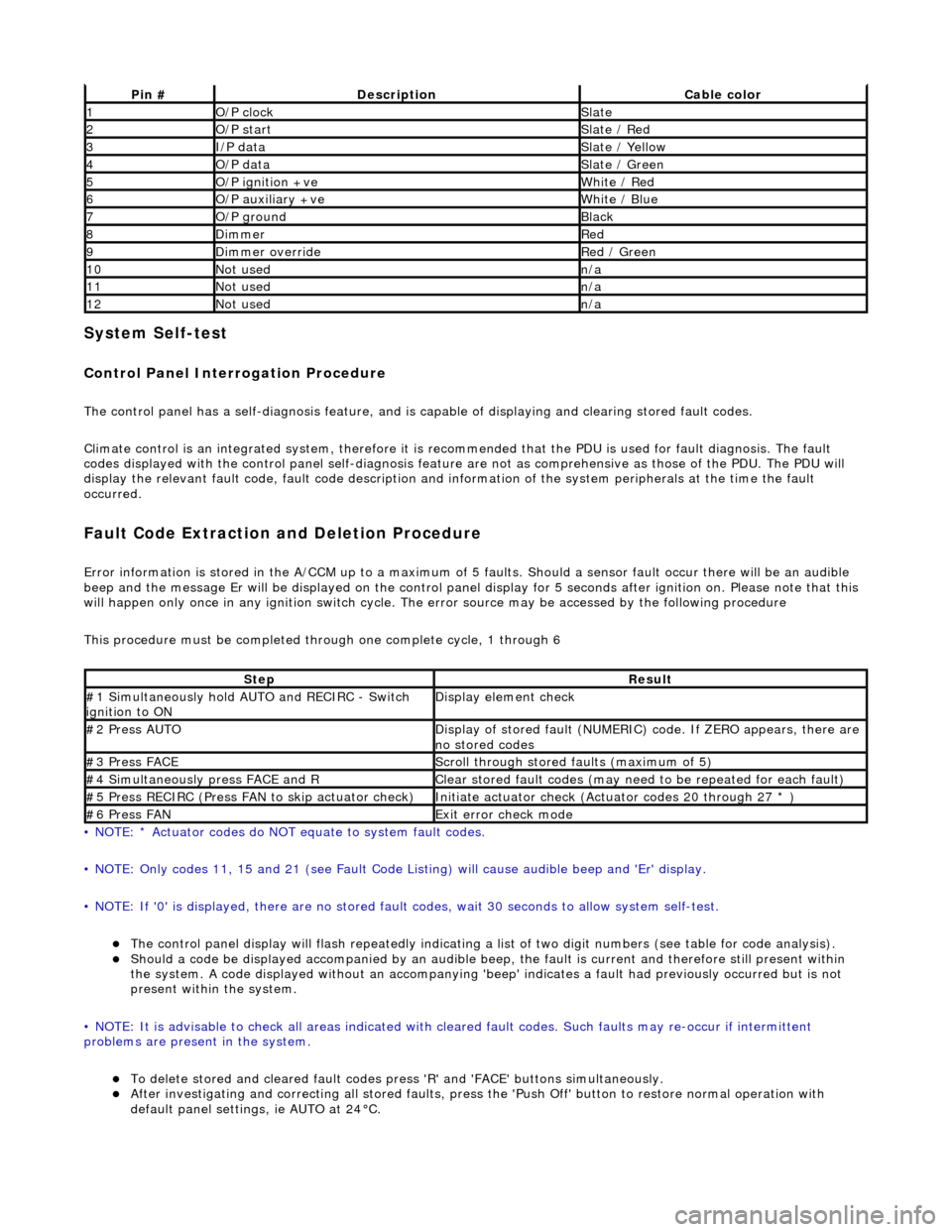
System Self-test
Control Panel Interrogation Procedure
The control panel has a self-diagnosis feature, and is capable of displaying and clearing stored fault codes.
Climate control is an integrated system, therefore it is recommended that the PDU is used for fault diagnosis. The fault
codes displayed with the control panel self -diagnosis feature are not as comprehensive as those of the PDU. The PDU will
display the relevant fault code, fault co de description and information of the system peripherals at the time the fault
occurred.
Fault Code Extraction and Deletion Procedure
Error information is stored in the A/CCM up to a maximum of 5 faults. Should a sensor fault occur there will be an audible
beep and the message Er will be displayed on the control panel display for 5 seco nds after ignition on. Please note that this
will happen only once in any ignition switch cycle. The error source may be accessed by the following procedure
This procedure must be completed through one complete cycle, 1 through 6
• NOTE: * Actuator codes do NOT equate to system fault codes.
• NOTE: Only codes 11, 15 and 21 (see Fault Code List ing) will cause audible beep and 'Er' display.
• NOTE: If '0' is displayed, there are no stored faul t codes, wait 30 seconds to allow system self-test.
The control panel display will flash repeatedly indicating a list of two digit numbers (see table for code analysis). Should a code be displayed accompanied by an audible beep, the fault is current and therefore still present within
the system. A code displayed without an accompanying 'bee p' indicates a fault had previously occurred but is not
present within the system.
• NOTE: It is advisable to check all areas indicated with cleared fault codes. Such faults may re-occur if intermittent
problems are present in the system.
To delete stored and cleared fault codes press 'R' and 'FAC E' buttons simultaneously. After investigating and correcting all stored faults, press the 'Push Off' button to restore normal operation with
default panel settings, ie AUTO at 24°C.
Pin #DescriptionCable color
1O/P clockSlate
2O/P startSlate / Red
3I/P dataSlate / Yellow
4O/P dataSlate / Green
5O/P ignition +veWhite / Red
6O/P auxiliary +veWhite / Blue
7O/P groundBlack
8DimmerRed
9Dimmer overrideRed / Green
10Not usedn/a
11Not usedn/a
12Not usedn/a
StepResult
#1 Simultaneously hold AU TO and RECIRC - Switch
ignition to ONDisplay element check
#2 Press AUTODisplay of stored fault (NUMERIC) code. If ZERO appears, there are
no stored codes
#3 Press FACEScroll through stored faults (maximum of 5)
#4 Simultaneously press FACE and RClear stored fault codes (may need to be repeated for each fault)
#5 Press RECIRC (Press FAN to skip actuator check)Initiate actuator check (Actuator codes 20 through 27 * )
#6 Press FANExit error check mode
Page 1979 of 2490
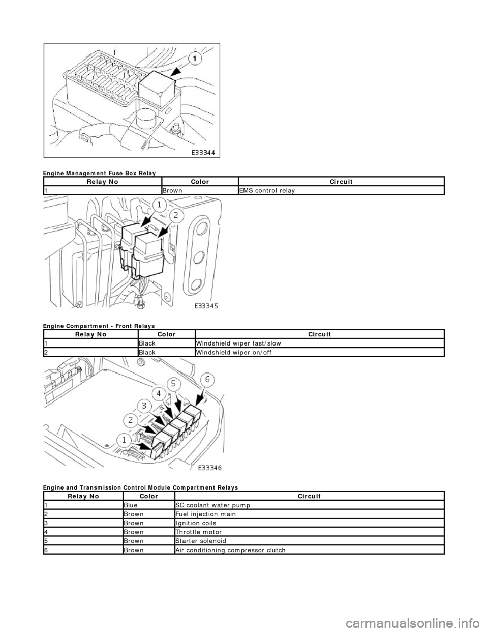
Engine Management Fuse Box Relay
Engine Compartment - Front Relays
Engine and Transmission Control Module Compartment Relays
Relay NoColorCircuit
1BrownEMS control relay
Relay NoColorCircuit
1BlackWindshield wiper fast/slow
2BlackWindshield wiper on/off
Relay NoColorCircuit
1BlueSC coolant water pump
2BrownFuel injection main
3BrownIgnition coils
4BrownThrottle motor
5BrownStarter solenoid
6BrownAir conditioning compressor clutch
Page 1980 of 2490
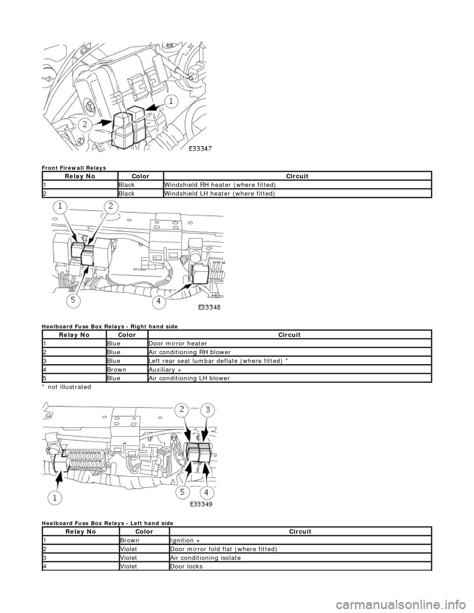
Front Firewall Relays
Heelboard Fuse Box Relays - Right hand side
* not illustrated
Heelboard Fuse Box Relays - Left hand side
Relay NoColorCircuit
1BlackWindshield RH heater (where fitted)
2BlackWindshield LH heater (where fitted)
Relay NoColorCircuit
1BlueDoor mirror heater
2BlueAir conditioning RH blower
3BlueLeft rear seat lumbar deflate (where fitted) *
4BrownAuxiliary +
5BlueAir conditioning LH blower
Relay NoColorCircuit
1BrownIgnition +
2VioletDoor mirror fold flat (where fitted)
3VioletAir conditioning isolate
4VioletDoor locks
Page 1990 of 2490
the bag securely before opening another bag. Also, replace the bag in its mating part number compartment within the case.
The pre-terminated wiring harness(s) are su pplied with the insulation in one of three colors, red, blue or yellow. The colors
do not apply to any particular circuit but to the harness wire size. See the Relationship Table in the Repair Method section.
Butt splice connectors are also supplied wi th red, blue or yellow coverings, which must be matched to the pre-terminated
wiring harness insulation color.
Pre-Terminated Wiring Harness(s)