1998 JAGUAR X308 dimensions
[x] Cancel search: dimensionsPage 58 of 2490

Suspension System - General Informatio
n -
Lubric
ants, Fluids, Sealants and Adhesives
Front Suspension Dimensions
• NO
TE: When a component reaches its maximum / minimum dimension limit the component must be replaced.
Rear sus
p
ension Dimensions
•
NO
TE: When a component reaches its maximum / minimum dimension limit the component must be replaced.
Vehicle ride
height
R i
de height is measured from
the center of the wheel to the apex of the wheel arch, through the wheel center line.
Showroom is with a
ll fluids at full an
d 9 liters (9.5 US quarts) of fuel.
Curb is
with all fluids at full and a full tank of fuel.
All f
i
gures quoted assume a ±
15 mm (0.59in) anticipated bu ild variance and condition.
Whee
l Alignment - Front Camber - XJR Excluding NAS, and German Super-8
Al l the above fi
gures
are at "showroom" height. (See ride height section above).
Tires must be infl
ated
to normal pressure.
For additional informat ion, refer to Section 204
-04
Wheels and Tires
.
Whe
e
l Alignment - Front Camber - XJR NAS, and Comfort/Sport/Daimler Super-8
UnitSp
ecification
Loctite27
0
Greas eShell Retin a
x 'A'
Greas
eCastro l 'NT
R'
Com
p
onent
Di
mensi
on
Hub face
-
maximum run-out
0.
03
8 mm
Com
p
onent
Di
mensi
on
Hub face
-
maximum run-out
0.
05
7 mm
Mod
e
l
Mod
e
l Year
V
I
N RANGE
Mark
et
Sh
owroom mm(in)
Curb mm(i
n)
FromToFron
t
RearFr
on
t
Rear
Com
f
ort suspension
1
998
to 2003.5
8
123
17
F
595
25
All3
90 (
15.11)
3
84 (
15.11)
3
89 (
15.31)
3
73 (
14.68)
Sport su
spe
nsion
"""All3
89 (
15.31)
3
81 (
15.00)
3
88 (
15.27)
3
72 (
14.64)
XJR"""NAS3
89 (
15.31)
3
82 (
15.03)
3
88 (
15.27)
3
72 (
14.64)
XJR"""RO
W367 (
14.44)
3
65 (
14.37)
3
66 (
14.40)
3
58 (
14.09)
Supercharged super 8"""All3
89 (
15.31)
3
82 (
15.03)
3
88 (
15.27)
3
72 (
14.64)
XJR
Excluding NAS, and German Super-8
1998 to
2003.5
VIN - 812317 to F59525
Units
Cambe r
Left
- Hand
Rig
h
t - Hand
Bal
a
nce (RH - LH)
MinMaxMinMaxMinMax
All Right-Hand driv
e and JapanDegrees
/minutes
-
1
° 28'
-0
°
28'
-
1
° 13'
-
0
° 13'
-0
° 45'+1 °
15'
Decimal degrees-1.
4
7°
-0
.4
7°
-1
.2
2°
-0.
2
2°
-0
.7
5°
+1
.25
°
R
e
st of World
De
grees
/minutes
-
1
° 13'
-0
°
13'
-
1
° 28'
-
0
° 28'
-1
° 15'+0 °
45'
Decimal degrees-1.
2
2°
-0
.2
2°
-1
.4
7°
-0.
4
7°
-1
.2
5°
+0
.75
°
XJR
NAS, and Comfort/Sport/Daimler Super-8
1
998 to
2003.5
VIN - 812317 to F59525
Units
Cambe r
Left
- Hand
Rig
h
t - Hand
Bal
a
nce (RH -
LH)
MinMaxMinMaxMinMax
All Right-Hand drive and JapanDegrees
/minutes
-1°
02'-0
° 02'
-0°
47'
+0°
13'
-0° 45'+1°
15'
Decimal degrees-1.0
3°
-0.0
3°
-0.7
8°
+0.22
°
-0.7
5°
+1.25
°
USA, Canada an
d Mexico,
Dominican
Republic (NAS)
De grees
/minutes
-0°
32 '+0 °
28'
-1 °
02'
-0 °
02'
-1°
30 '+0 °
30'
Decimal degrees-0. 5
3°
+0
.47
°
-1
.0
3°
-0
.0
3°
-1.
5
0°
+0
.50
°
R
e
st of World
De
grees
/minutes
-0°
47 '+0 °
13'
-1 °
02'
-0 °
02'
-1°
15 '+0 °
45'
Decimal degrees-0. 7
8°
+0
.22
°
-1
.0
3°
-0
.0
3°
-1.
2
5°
+0
.75
°
Page 307 of 2490

Brake S
ystem - General Information -
Lu
bricants, Fluids, Sealants and Adhesives
Front Brake Dimensions
• NO
TE: When a component reaches its maximum / minimum dimension limit the component must be replaced. Care must be
taken when refinishing brake discs that the dimension limits are not exceeded.
F
ront Brake Dimensions - Brembo Brakes
• NO
TE: When a component reaches its maximum / minimum dimension limit the component must be replaced. Care must be
taken when refinishing brake discs and drums that the dimension limits are not exceeded.
R
ear Brake Dimensions
• NO
TE: When a component reaches its maximum / minimum dimension limit the component must be replaced. Care must be
taken when refinishing brake discs and drums that the dimension limits are not exceeded.
R
ear Brake Dimensions - Brembo Brakes
• NO
TE: When a component reaches its maximum / minimum dimension limit the component must be replaced. Care must be
taken when refinishing brake discs and drums that the dimension limits are not exceeded.
UnitSp
ecification
Bra
ke fluid
IT
T Super Dot 4
Brembo Br
ake Grease
M
olikote Cu 7439
Co
mponent
Dimension - Normall
y Aspirated Vehicle
Dimension
- Super Charged Vehicle
Brake disc
- diameter
305 mm325 mm
Brake disc
- thickness (new)
28
- 28.5 mm
28 -
28.5 mm
B
rake disc - minimum thickness
26 mm26 mm
B
rake disc - minimum wall thickness
6.2 mm6.6 mm
I
nstalled brake disc - maximum run-out
0.1 mm0.1 mm
B
rake pad - minimum thickness
2 mm2 mm
Cal
iper piston diameter
60 mm60 mm
Co
mponent
Dimension
Brake disc
- diameter
355 mm
Brake disc
- thickness (new)
32 mm
B
rake disc - minimum thickness
30 mm
B
rake disc - minimum wall thickness
6.7 mm
I
nstalled brake disc - maximum run-out
0.1 mm
Cal
iper piston diameter
40/44 equiv
alent 60 mm
B
rake pad - minimum thickness
2 mm
Co
mponent
Dimension
Brake disc
- diameter
305 mm
Brake disc
- thickness (new)
19.5
- 20 mm
B
rake disc - minimum thickness
18.5 mm
B
rake disc - minimum wall thickness
4.9 mm
I
nstalled brake disc - maximum run-out
0.15 mm
Cal
iper piston diameter
42 mm
Pa
rking brake drum - maximum diameter
181 mm
B
rake pad - minimum thickness
2 mm
Pa
rking brake shoes - minimum thickness
2 mm
Co
mponent
Dimension
Brake disc
- diameter
330 mm
Brake disc
- thickness (new)
28 mm
B
rake disc - minimum thickness
26 mm
B
rake disc - minimum wall thickness
6.7 mm
I
nstalled brake disc - maximum run-out
0.1 mm
Cal
iper piston diameter
28/30 equiv
alent 41 mm
B
rake pad - minimum thickness
2 mm
Page 341 of 2490

• C
AUTIONS:
The Brembo caliper is aligned to the brak e disc when it is first installed to the vehicle, therefore, care must be taken
not to disturb this alignment. When removi ng the caliper; remove the bolts that secure the anchor bracket to the vertical
link only. DO NOT loosen any other caliper bolts.
Do not loosen bolts securing brake disc to disc mounting.
Brembo calipers and discs provide higher -performance braking using the existing hydraulic braking system. The brakes are
installed to the vehicle using unique vertical links, hubs, hydraulic hoses and disc shields.
The front brake disc consists of a ventilated, cross-drilled disc, bolted to a disc carrier. The disc assemb ly is mounted on the
wheel studs and clamped be tween the wheel and hub.
A unique feature of the front disc is th e slanted (non radial) ventilation webs which lean the opposite-way to the disc's
direction of rotation. This design enables he at generated by the disc to be dispersed by air entering at the disc's center and
being forced outwards through the cooling ducts.
Due to the use of fixed calipers in place of the standard floating caliper, certain lateral dimensions on the vertical link and
It
em
Par
t Number
De
scription
1—B
rake Disc
2—Caliper
3—Anch
or Bracket
4—Anchor Pl
ate to Vertical Link - Bolts
5—Brake Pad
s
6—Guide P
ins
7—Anti-r
attle Spring
8—Di
sc Shield
9—Brake Hos
e
10—Bleed Nipp
les
Front Disc Brake—
Brembo
Page 366 of 2490

CAUTI O
N: The Brembo caliper is aligned to
the brake disc when it is first installed to the vehicle, therefore, care must
be taken not to disturb this alignment. When removing the ca liper; remove the bolts that secure the anchor bracket to the
hub carrier only. DO NOT loos en any other caliper bolts.
Brembo calipers and discs provide higher -performance braking using the existing hydraulic braking system. The brakes are
installed to the vehicle using unique hub carr iers, hubs, hydraulic hoses and disc shields.
The rear brake disc is a single piece co nstruction which is ventilated and cross-drilled. The disc is mounted on the wheel
studs and is clamped between the wheel and hub. Cooling ducts run through the ce nter of the brake disc to provide the
required ventilation to keep the disc cool under operating conditions.
Modified disc shields are installed to accommodate the larger diameter discs.
Due to the use of fixed calipers in place of the standard floating caliper, certain lateral dimensions on the hub carriers and
hubs are critical to achieve correct cleara nce and operation of the brakes. Therefore special hub carriers and hubs set within
a certain tolerance are inst alled with Brembo brakes.
The four cylinder brake caliper is rigidly attached to the vert ical link via an anchor bracket. The caliper is a split assembly
with each side of the caliper, housing two pistons. The two-pairs of opposed pistons act direct ly on the brake pads mounted
one each side of the disc.
It e
m
Par
t
Number
De
scr
iption
1—Brake D
i
sc
2—Caliper Housin
g
3—Anchor Bracke
t
4—Anchor Bracket to H
u
b Carrier - Bolts
5—Brake Pads
6—Guide Pi
ns
7—An
ti
-rattle Sprin
g
8—Di
sc
Shield
9—Brake Hos
e
10—Bleed Nipp
les
Rear Disc Brake - Brembo
Page 2386 of 2490

Body Structure
Introduction
The standard wheelbase Jaguar sedan has a unit construction monocoque body structure with bolt-on front fenders and
welded rear fenders. The doors feature lif t-off hinges and welded drop-glass frames.
Constructional Steel Classification
BODY ALIGNMENT
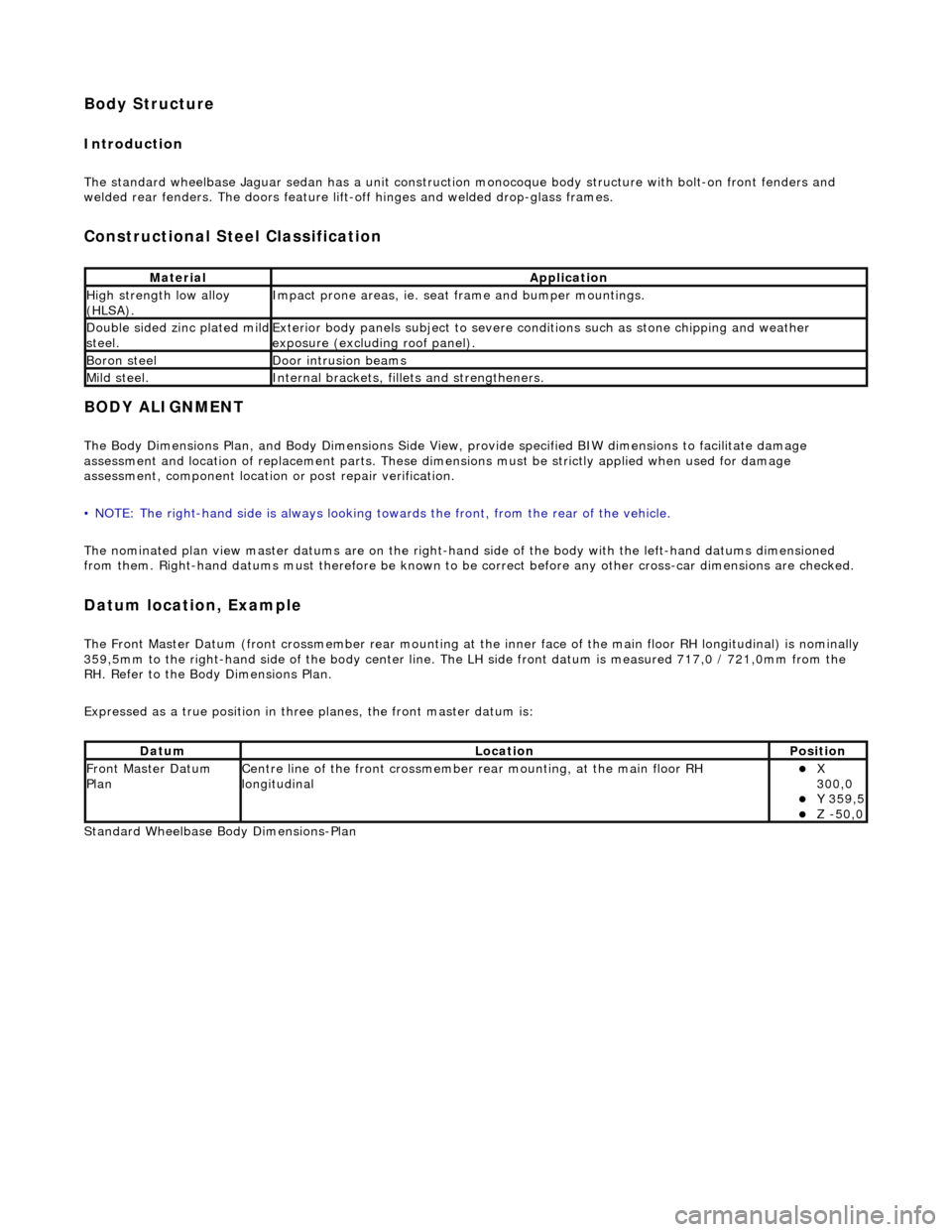
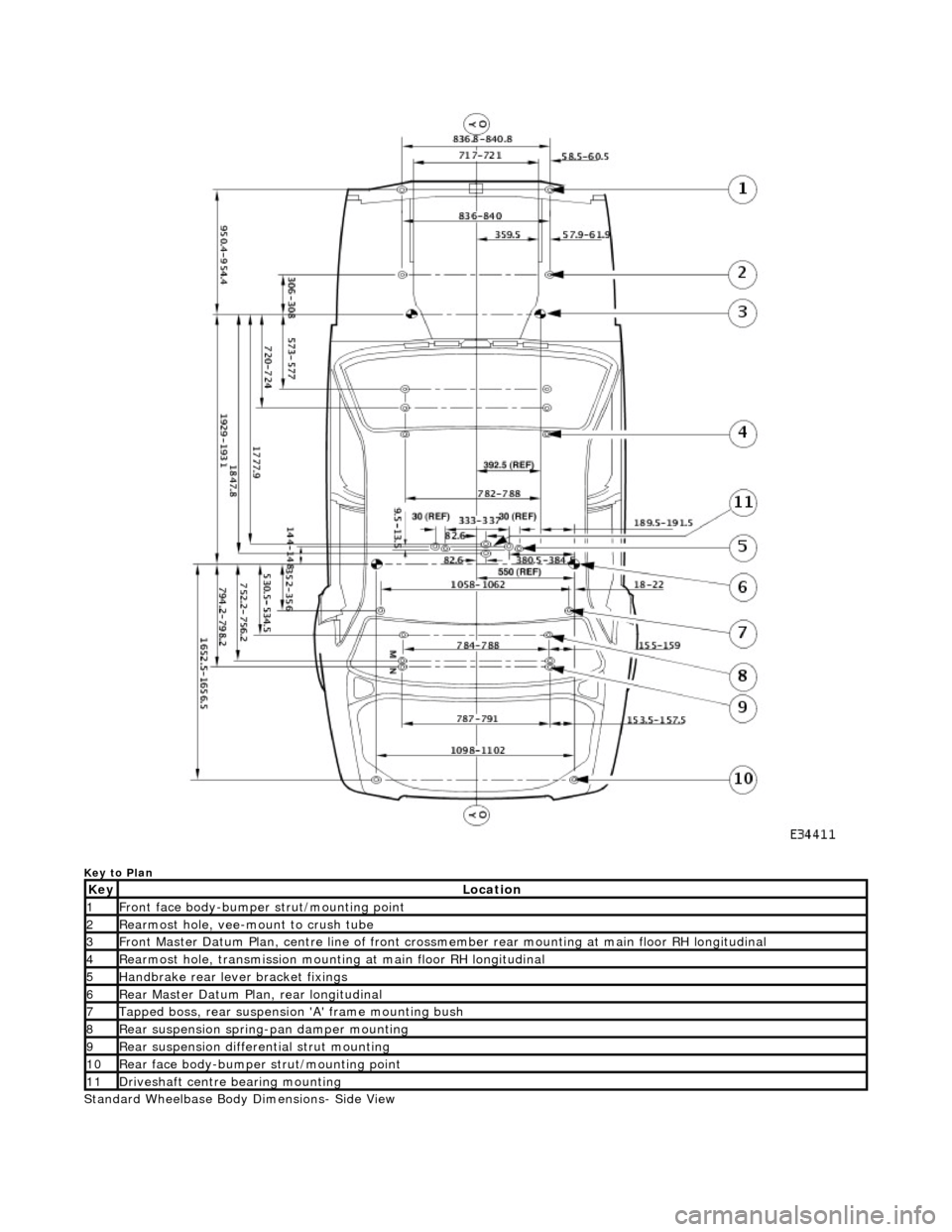
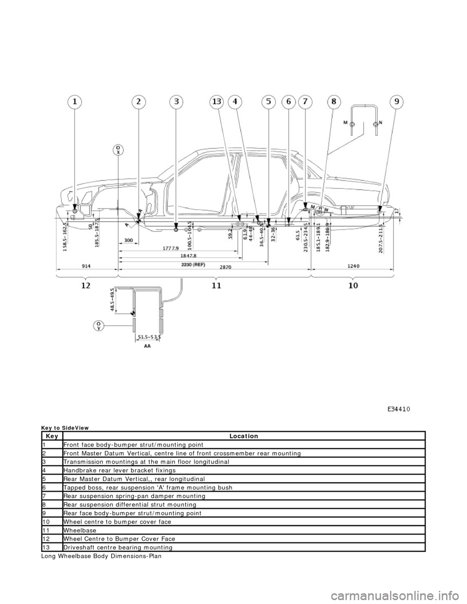
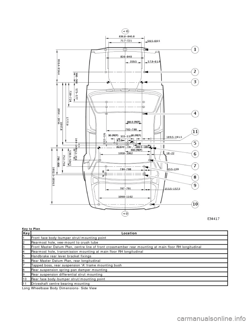
The Body Dimensions Plan, and Body Dimensions Side View, provide specified BIW dimensions to facilitate damage
assessment and location of replacemen t parts. These dimensions must be strictly applied when used for damage
assessment, component location or post repair verification.
• NOTE: The right-hand side is always looking towards the front, from the rear of the vehicle.
The nominated plan view master datums are on the right-hand side of the body with the left-hand datums dimensioned
from them. Right-hand datums must therefore be known to be correct before any other cross-car dimensions are checked.
Datum location, Example
The Front Master Datum (front crossmember rear mounting at the inner face of the main floor RH longitudinal) is nominally
359,5mm to the right-hand side of the body center line. The LH side fron t datum is measured 717,0 / 721,0mm from the
RH. Refer to the Body Dimensions Plan.
Expressed as a true posi tion in three planes, the front master datum is:
Standard Wheelbase Bo dy Dimensions-Plan
MaterialApplication
High strength low alloy
(HLSA).Impact prone areas, ie. seat frame and bumper mountings.
Double sided zinc plated mild steel.Exterior body panels subject to severe cond itions such as stone chipping and weather
exposure (excluding roof panel).
Boron steelDoor intrusion beams
Mild steel.Internal brackets, fill ets and strengtheners.
DatumLocationPosition
Front Master Datum
PlanCentre line of the front crossmember rear mounting, at the main floor RH
longitudinalX
300,0
Y 359,5 Z -50,0
Page 2387 of 2490

Key to Plan
Standard Wheelbase Body Dimensions- Side View
KeyLocation
1Front face body-bumper strut/mounting point
2Rearmost hole, vee-mount to crush tube
3Front Master Datum Plan, centre li ne of front crossmember rear mount ing at main floor RH longitudinal
4Rearmost hole, transmission mounting at main floor RH longitudinal
5Handbrake rear lever bracket fixings
6Rear Master Datum Plan, rear longitudinal
7Tapped boss, rear suspension 'A' frame mounting bush
8Rear suspension spring-pan damper mounting
9Rear suspension differential strut mounting
10Rear face body-bumper strut/mounting point
11Driveshaft centre bearing mounting
Page 2388 of 2490

Key to SideView
Long Wheelbase Body Dimensions-Plan
KeyLocation
1Front face body-bumper strut/mounting point
2Front Master Datum Vertical, centre line of front crossmember rear mounting
3Transmission mountings at the main floor longitudinal
4Handbrake rear lever bracket fixings
5Rear Master Datum Vertical,, rear longitudinal
6Tapped boss, rear suspensi on 'A' frame mounting bush
7Rear suspension spring-pan damper mounting
8Rear suspension differential strut mounting
9Rear face body-bumper strut/mounting point
10Wheel centre to bumper cover face
11Wheelbase
12Wheel Centre to Bumper Cover Face
13Driveshaft centre bearing mounting
Page 2389 of 2490

Key to Plan
Long Wheelbase Body Dimensions- Side View
KeyLocation
1Front face body-bumper strut/mounting point
2Rearmost hole, vee-mount to crush tube
3Front Master Datum Plan, centre line of front crossmember rear mount ing at main floor RH longitudinal
4Rearmost hole, transmission mounting at main floor RH longitudinal
5Handbrake rear lever bracket fixings
6Rear Master Datum Plan, rear longitudinal
7Tapped boss, rear suspension 'A' frame mounting bush
8Rear suspension spring-pan damper mounting
9Rear suspension differential strut mounting
10Rear face body-bumper strut/mounting point
11Driveshaft centre bearing mounting