Page 1490 of 2490
Automatic Transmission/Transaxle External Controls - 4.0L NA V8 -
AJ27/3.2L NA V8 - AJ 26 - Selector Lever Gate Finish Panel
Removal and Installation
Removal
Installation
1.
Apply protective tape to veneer along each side of 'J' gate
finisher.
2. Using a screwdriver in the slot in front of the finisher,
carefully lift the finisher an d ease it from the 'J' gate
surround.
1. Position finisher over gear selector.
2. Firmly seat finisher on veneer panel.
3. Remove protective tape from ve neer panel and using a suitable
cleaner, remove any residual adhesive.
Page 1493 of 2490
Automatic Transmission/Transaxle External Controls - 4.0L NA V8 -
AJ27/3.2L NA V8 - AJ26 - Selector Lever Switch
Removal and Installation
Removal
Installation
1. Disconnect battery ground cable.
Remove the battery cover.
2. Remove the gear shift knob, (44.15.06).
3. Remove the console finisher veneer panel, (76.47.26).
4. Remove the 'J Gate' surroun d for access, (76.25.24).
5. Remove the D to 4 switch.
Press the retaining tangs to release.
1. Fitting a new D to 4 switch is the reverse of the removal
procedure.
2. Connect the battery and fit the battery cover.
Reset the radio and the clock.
Page 1516 of 2490
Automatic Transmission/Transaxle External Contro ls - 4.0L SC V8 - AJ26 -
Selector Lever Gate Finish Panel
Removal and Installation
Removal
Installation
1.
Apply protective tape to veneer along each side of 'J' gate
finisher.
2. Using a screwdriver in the slot in front of the finisher,
carefully lift the finisher an d ease it from the 'J' gate
surround.
1. Position finisher over gear selector.
2. Firmly seat finisher on veneer panel.
3. Remove protective tape from ve neer panel and using a suitable
cleaner, remove any residual adhesive.
Page 1520 of 2490
moving the set position of either the gear selector lever or the selector lever on the transmission casing.
3. Tighten to 22-28 Nm.
4. Verify the 'N' setting.
6. Check that all released connec tors are safely insulated and
connect the vehicle battery.
7. Switch ON the ignition.
8. Adjust the position of the linear switch so that the selector 'N'
position graphic illuminates. Ti ghten the four screws to 0,7-1
Nm.
9. Move the gear selector to 'R' to confirm that the 'R' position
graphic illuminates.
10. Check that the engine will start when the gear selector is in
the 'N' and 'P' positions, bu t not in any other position.
11. Move the gear selector to 'N'.
12. Switch OFF the ignition.
13. Disconnect the battery.
14. Install the console assembly, operation 76.25.01.
15. Install the console finisher veneer panel, operation 76.47.26.
16. Install the J-gate surround, operation 76.25.24.
17. Perform the Battery Reconnection Procedure described in
Operation 86.15.15.
Page 1777 of 2490

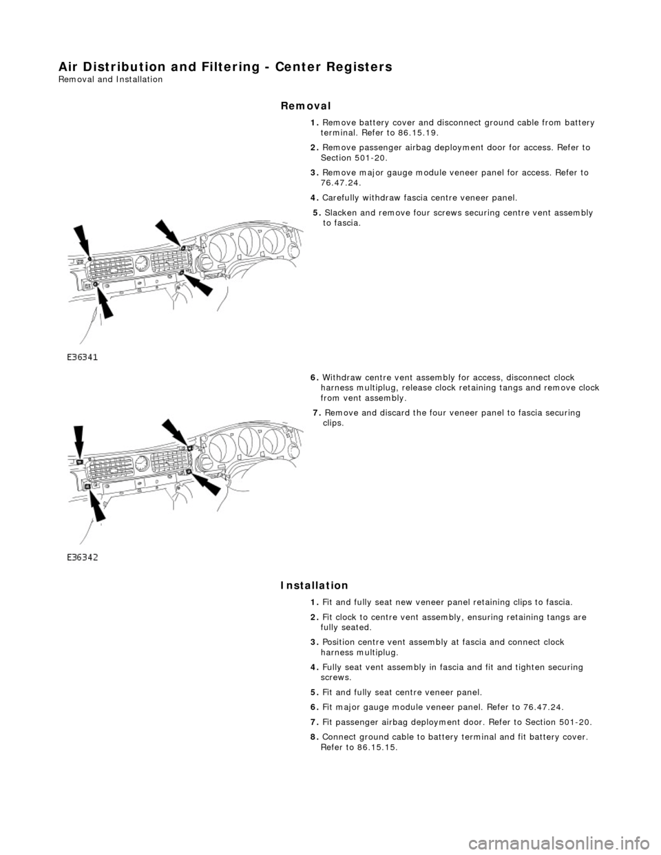
Air Distribution and Filtering - Center Registers
Removal and Installation
Removal
Installation
1.
Remove battery cover and disconnect ground cable from battery
terminal. Refer to 86.15.19.
2. Remove passenger airbag deployment door for access. Refer to
Section 501-20.
3. Remove major gauge module veneer panel for access. Refer to
76.47.24.
4. Carefully withdraw fascia centre veneer panel.
5. Slacken and remove four screws securing centre vent assembly
to fascia.
6. Withdraw centre vent assembly for access, disconnect clock
harness multiplug, release clock retaining tangs and remove clock
from vent assembly.
7. Remove and discard the four veneer panel to fascia securing
clips.
1. Fit and fully seat new veneer panel retaining clips to fascia.
2. Fit clock to centre vent assemb ly, ensuring retaining tangs are
fully seated.
3. Position centre vent assembly at fascia and connect clock
harness multiplug.
4. Fully seat vent assembly in fascia and fit and tighten securing
screws.
5. Fit and fully seat centre veneer panel.
6. Fit major gauge module veneer panel. Refer to 76.47.24.
7. Fit passenger airbag deployment door. Refer to Section 501-20.
8. Connect ground cable to battery terminal and fit battery cover.
Refer to 86.15.15.
Page 1857 of 2490
Instrume
nt Cluster - Instrument Cluster
Re
moval and Installation
Remov
al
1.
Adjust steer
ing column to full
y extended and lowered position.
2. Remove battery cover and disc onnect ground cable from
battery terminal. Refer to 86.15.19.
3. Remove veneer from instrument panel. Refer to 76.47.24.
4. Using a small
screwdriver, de
press fog lamp switch upper
retaining tang and release sw itch from gauge surround.
5. Position fog l
amp switch fo
r access, disconnect harness
multiplug and remove switch.
6. Using a small
screwdriver, depress trip keyboard upper
retaining tang and release ke yboard from gauge surround.
7. Position trip keyboard for ac cess and disconnect harness
multiplug.
Page 1858 of 2490
In
stallation
8.
Slac ken an
d remove four screws securing major gauge
module/surround to fascia and withdraw surround.
9. With draw major gau
ge module fo
r access, disconnect the two
harness multiplugs and remove gauge module from fascia.
1. Position major gauge module in fascia and connect both
harness multiplugs.
2. Position major gauge surround on panel, routing harness
multiplugs through apertures.
3. Fit and tighten screws securing major gauge module/surround
to fascia.
4. Connect harness multiplug to tr ip keyboard and fit and fully
seat keyboard in gauge surround, ensuring correct location of
retaining tangs
5. Connect harness multiplug to fog lamp switch and fit and fully
seat switch in gaug e surround, ensuring correct location of
tangs.
6. Fit veneer panel. Refer to 76.47.24.
7. Connect ground cable to battery terminal and fit battery cover.
Refer to 86.15.15.
8. Return steering column to original position.
Page 1867 of 2490
Information and Message Center - Message Center Switch
Removal and Installation
Removal
Installation
1.
Disconnect battery ground cable; refer to 86.15.19.
2. Remove instrument panel veneer panel; refer to 76.47.24.
3. Remove trip computer switch pack.
Use suitable small screwdriver to displace upper retaining
tang.
Reposition switch pack for access to connector.
Disconnect connector and remove switch pack.
1. Installation is reverse of removal.