1998 JAGUAR X308 fuel diagram
[x] Cancel search: fuel diagramPage 1016 of 2490
Pa
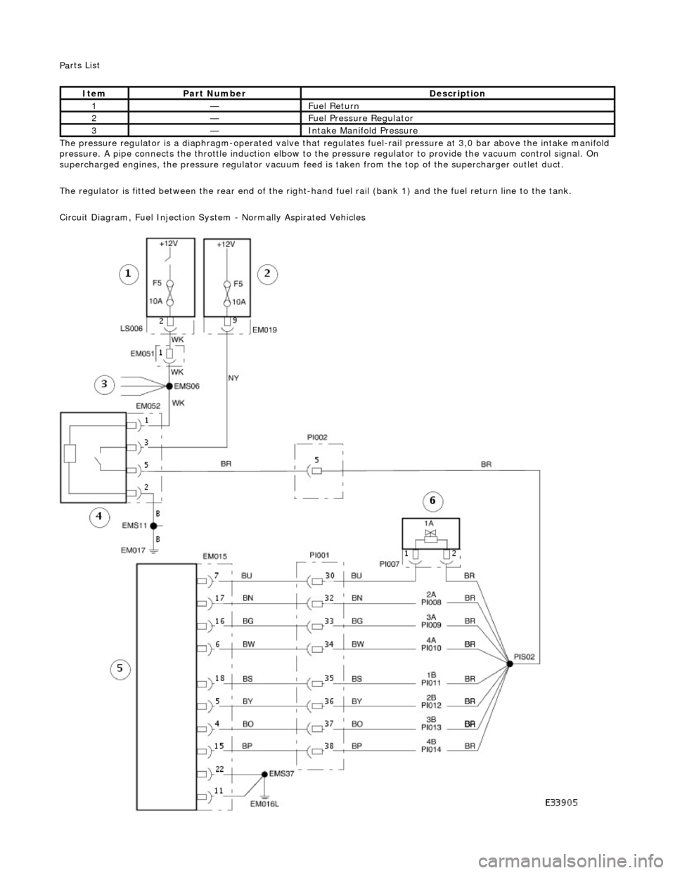
rts List
The pressure regulator is a diap hragm-operated valve that regula tes fuel-rail pressure at 3,0 bar above the intake manifold
pressure. A pipe connects the throttle induction elbow to the pressure regulator to provide the vacuum control signal. On
supercharged engines, the pressure regulator vacuum feed is taken from the top of the supercharger outlet duct.
The regulator is fitted between the rear end of the right-hand fuel rail (bank 1) and the fuel return line to the tank.
Circuit Diagram, Fuel Injection Syst em - Normally Aspirated Vehicles
Ite
m
Par
t
Number
De
scr
iption
1—F
u
el Return
2—F
u
el Pressure Regulator
3—Inta
k
e Manifold Pressure
Page 1017 of 2490
Ci
rcuit references to injectors:
'A' refers to bank 1;
'B' refers to bank 2.
Fuel C
harging and Controls - Supercharged Vehicles
Ci
rcuit Diagram, Fuel Injection
System - Supercharged Vehicles
It
em
Par
t Number
De
scription
1—E
ngine compartment fuse-box
2—Engine
management fuse-box
3—Splice
- 12V to
other circuits
4—PI m
ain relay
5—Engine
control module (ECM)
6—Fue
l injector 1A - other injectors similar
Page 1022 of 2490
(ECT) se
nsor
Blocked part-load breather
(s
ervice action S474)
Injec
t
or leak
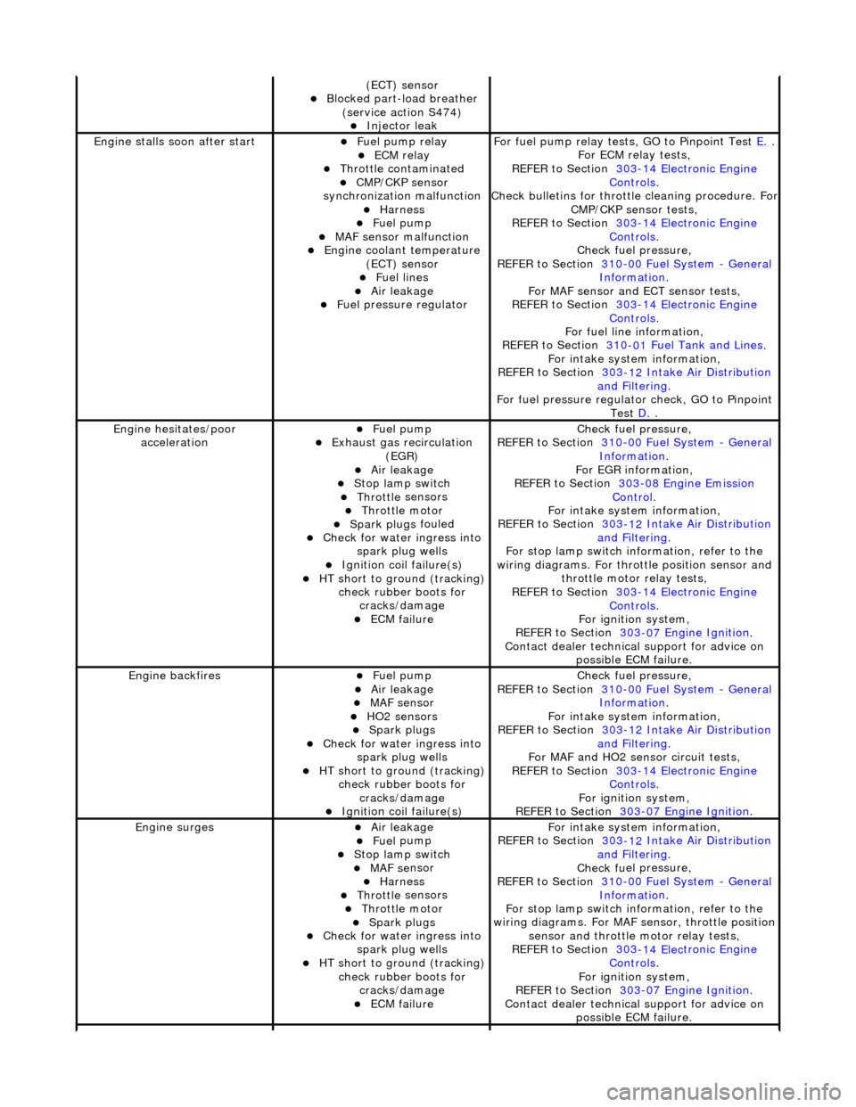
Engine stalls
soon
after start
F
u
el pump relay
ECM relay Thr
o
ttle contaminated
CMP/CKP sen
s
or
synchronization malfunction
Harness Fuel
pump
MAF
s
ensor malfunction
Engine coolan
t
temperature
(ECT) sensor
Fue l
lines
Air leakage Fu
el pressure regulator
F
o
r fuel pump relay tests,
GO to Pinpoint Test E.
.
F or ECM
relay tests,
REFER to Section 303
-14 Elec tronic En
gine
Controls.
Check bull etins for throttl
e cleaning procedure. For
CMP/CKP sensor tests,
REFER to Section 303
-14 Elec tronic En
gine
Controls.
Chec k fu
el pressure,
REFER to Section 310
-00 Fu
el System
- Ge
n
eral
Informati
o
n
.
F or MAF sensor and
ECT sensor tests,
REFER to Section 303
-14 Electronic En
gine
Controls.
For fuel l
ine information,
REFER to Section 310
-01
Fuel Tank and Lines
.
F or i
ntake system information,
REFER to Section 303
-1 2
Intake Air Distribution
and F
ilt
ering
.
F o
r fuel pressure regulato
r check, GO to Pinpoint
Test D.
.
Engine h e
sitates/poor
acceleration
Fue l
pump
Exhaus
t gas
recirculation
(EGR)
Air leakage Stop lamp swi t
ch
Throttl
e
sensors
Throttl
e
motor
Spark plugs
fouled
Check f
o
r water ingress into
spark plug wells
Ignition coil fail
ure(s)
HT sho
rt to ground (tracking)
check rubber
boots for
cracks/damage
ECM failu r
e
Chec
k fu
el pressure,
REFER to Section 310
-00 Fu
el System
- Ge
n
eral
Informati
o
n
.
F o
r EGR information,
REFER to Section 303
-08 En gin
e Emission
Control.
F or i
ntake system information,
REFER to Section 303
-1 2
Intake Air Distribution
and F
ilt
ering
.
F or stop l
amp switch in
formation, refer to the
wiring diagrams. For throttle position sensor and throttle motor relay tests,
REFER to Section 303
-14 Elec tronic En
gine
Controls.
For ign i
tion system,
REFER to Section 303
-07 En
gine Ignition
.
Contact dealer techn i
cal
support for advice on
possible ECM failure.
Engine ba ckfiresFuel
pump
Air leakage MAF s
e
nsor
HO2 sensors Spark plugs
Check fo
r water ingress into
spark plug wells
HT short to ground (tracking) check rubber
boots for
cracks/damage
Ignition coil fail
ure(s)
Chec
k fu
el pressure,
REFER to Section 310
-00 Fu
el System
- Ge
n
eral
Informati
o
n
.
F or i
ntake system information,
REFER to Section 303
-1 2
Intake Air Distribution
and F
ilt
ering
.
For MAF and HO2
sensor circuit tests,
REFER to Section 303
-14 Electronic En
gine
Controls.
For igni
tion system,
REFER to Section 303
-07 En
gine Ignition
.
Engine
s
urges
Air leakage Fue
l
pump
Stop lamp swi
t
ch
MAF s
e
nsor
Harness Throttl
e
sensors
Throttl
e
motor
Spark plugs
Check fo
r water ingress into
spark plug wells
HT sho rt to ground (tracking)
check rubber
boots for
cracks/damage
ECM failu r
e
F
or i
ntake system information,
REFER to Section 303
-1 2
Intake Air Distribution
and F
ilt
ering
.
Chec k fu
el pressure,
REFER to Section 310
-00 Fu
el System
- Gen
e
ral
Informati
o
n
.
F or stop l
amp switch in
formation, refer to the
wiring diagrams. For MAF se nsor, throttle position
sensor and throttle motor relay tests,
REFER to Section 303
-14 Elec tronic En
gine
Controls.
For ign i
tion system,
REFER to Section 303
-07 En
gine Ignition
.
Contact dealer techn i
cal
support for advice on
possible ECM failure.
Page 1029 of 2490
ci
rcuit includes the EMS fuse box,
fuse 05, and the fuel injection relay. For additional information,
refer to the wiring diagrams. CLEAR DTC. TEST the system for normal operation.
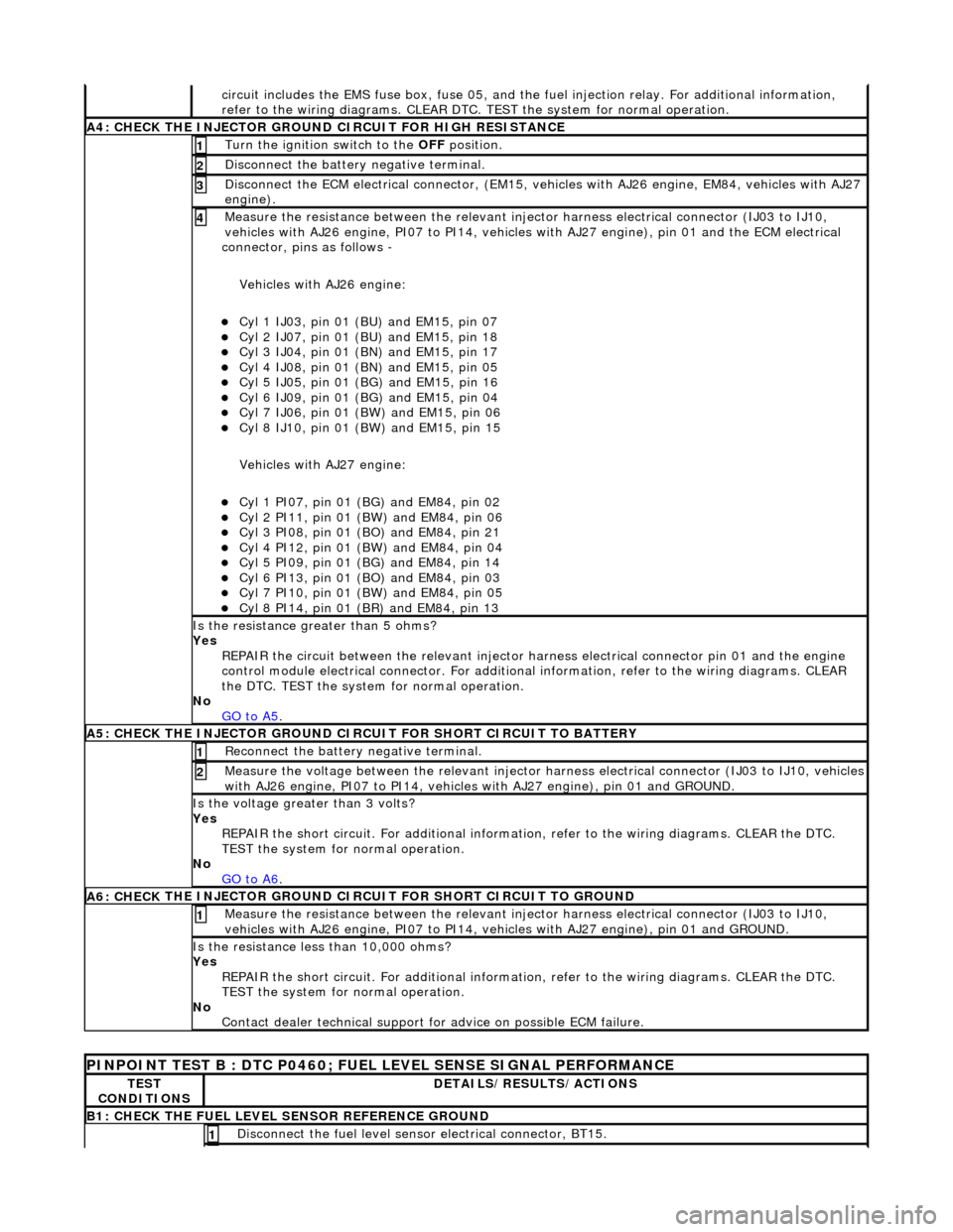
A4: CHECK
THE INJECTOR GROUND
CIRCUIT FOR HIGH RESISTANCE
Turn the ignition swi
tch to the OFF
position.
1
Di
sconnect the battery negative terminal.
2
D
isconnect the ECM electrical connector, (EM15, vehi
cles with AJ26 engine, EM84, vehicles with AJ27
engine).
3
Meas
ure the resistance between the relevant injector harness electrical connector (IJ03 to IJ10,
vehicles with AJ26 engine, PI07 to PI14, vehicles with AJ27 engine), pin 01 and the ECM electrical
connector, pins as follows -
Vehicles with AJ26 engine:
Cy
l 1 IJ03, pin 01 (BU) and EM15, pin 07
Cy
l 2 IJ07, pin 01 (BU) and EM15, pin 18
Cy
l 3 IJ04, pin 01 (BN) and EM15, pin 17
Cy
l 4 IJ08, pin 01 (BN) and EM15, pin 05
Cy
l 5 IJ05, pin 01 (BG) and EM15, pin 16
Cy
l 6 IJ09, pin 01 (BG) and EM15, pin 04
Cy
l 7 IJ06, pin 01 (BW) and EM15, pin 06
Cy
l 8 IJ10, pin 01 (BW) and EM15, pin 15
Vehicles with AJ27 engine:
Cy
l 1 PI07, pin 01 (B
G) and EM84, pin 02
Cy
l 2 PI11, pin 01 (BW) and EM84, pin 06
Cy
l 3 PI08, pin 01 (BO) and EM84, pin 21
Cy
l 4 PI12, pin 01 (BW) and EM84, pin 04
Cy
l 5 PI09, pin 01 (B
G) and EM84, pin 14
Cy
l 6 PI13, pin 01 (BO) and EM84, pin 03
Cy
l 7 PI10, pin 01 (BW) and EM84, pin 05
Cy
l 8 PI14, pin 01 (BR) and EM84, pin 13
4
Is th
e resistance greater than 5 ohms?
Yes REPAIR the circuit between the relevant injector harness electrical connector pin 01 and the engine
control module electrical connecto r. For additional information, refer to the wiring diagrams. CLEAR
the DTC. TEST the system for normal operation.
No GO to A5
.
A5: CHECK
THE INJECTOR GROUND CI
RCUIT FOR SHORT CIRCUIT TO BATTERY
R
econnect the battery negative terminal.
1
Meas
ure the voltage between the relevant injector harness electrical connector (IJ03 to IJ10, vehicles
with AJ26 engine, PI07 to PI14, vehicles with AJ27 engine), pin 01 and GROUND.
2
Is th
e voltage greater than 3 volts?
Yes REPAIR the short circuit. For addi tional information, refer to the wiring diagrams. CLEAR the DTC.
TEST the system for normal operation.
No GO to A6
.
A6: CHECK
THE INJECTOR GROUND CI
RCUIT FOR SHORT CIRCUIT TO GROUND
Meas
ure the resistance between the relevant injector harness electrical connector (IJ03 to IJ10,
vehicles with AJ26 engine, PI07 to PI14, vehicles with AJ27 engine), pin 01 and GROUND.
1
Is
the resistance less than 10,000 ohms?
Yes REPAIR the short circuit. For addi tional information, refer to the wiring diagrams. CLEAR the DTC.
TEST the system for normal operation.
No Contact dealer technical support for advice on possible ECM failure.
P
INPOINT TEST B : DTC P0460; FUEL
LEVEL SENSE SIGNAL PERFORMANCE
TE
ST
CONDITIONS
D
ETAILS/RESULTS/ACTIONS
B1: CHECK
THE FUEL LEVEL SENSOR REFERENCE GROUND
Di
sconnect the fuel level sensor electrical connector, BT15.
1
Page 1030 of 2490
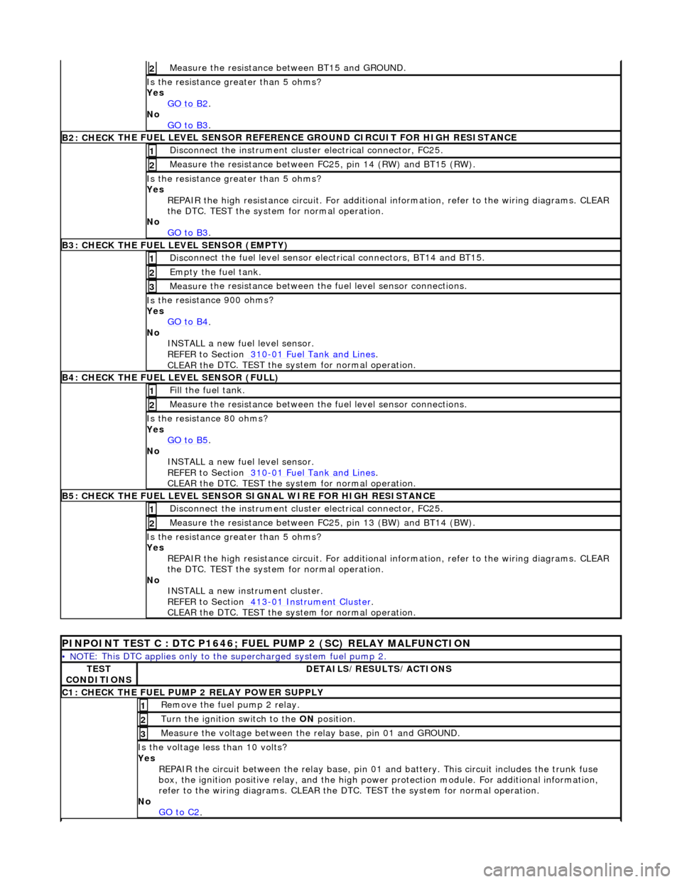
Measure t
he resistance
between BT15 and GROUND.
2
Is the res
istance greater than 5 ohms?
Yes GO to B2
.
No
GO to B3
.
B2: CHECK THE FUEL
LEVEL SENSOR REFERE
NCE GROUND CIRCUIT FOR HIGH RESISTANCE
Disc
onnect the instrument cluster electrical connector, FC25.
1
Meas
ure t
he resistance between FC25, pin 14 (RW) and BT15 (RW).
2
Is the res
istance greater than 5 ohms?
Yes REPAIR the high resistance circui t. For additional information, refer to the wiring diagrams. CLEAR
the DTC. TEST the system for normal operation.
No GO to B3
.
B3: CHECK THE FUEL
LEVEL SENSOR (EMPTY)
Di
sc
onnect the fuel level sensor electrical connectors, BT14 and BT15.
1
Empty the fuel
tank. 2
Measure t
he resistance between the
fuel level sensor connections.
3
Is t
he resistance 900 ohms?
Yes GO to B4
.
No
INST
ALL a new fuel level sensor.
REFER to Section 310
-0 1
Fuel Tank and Lines
.
CLEAR t h
e DTC. TEST the system for normal operation.
B4:
CHECK
THE FUEL LEVEL SENSOR (FULL)
Fi
ll
the fuel tank.
1
Meas
ure t
he resistance between the
fuel level sensor connections.
2
Is
the resistance 80 ohms?
Yes GO to B5
.
No
INST
ALL a new fuel level sensor.
REFER to Section 310
-0 1
Fuel Tank and Lines
.
CLEAR t h
e DTC. TEST the system for normal operation.
B
5
: CHECK THE FUEL LEVEL SENSOR SIGNAL WIRE FOR HIGH RESISTANCE
Di
sc
onnect the instrument cluster electrical connector, FC25.
1
Meas
ure t
he resistance between FC25, pin 13 (BW) and BT14 (BW).
2
Is th
e res
istance greater than 5 ohms?
Yes REPAIR the high resistance circui t. For additional information, refer to the wiring diagrams. CLEAR
the DTC. TEST the system for normal operation.
No INSTALL a new instrument cluster.
REFER to Section 413
-01
Instrume
nt Cluster
.
CLEAR t h
e DTC. TEST the system for normal operation.
P
INPOINT TEST C : DTC P1646; FU
EL PUMP 2 (SC) RELAY MALFUNCTION
•
NO
TE: This DTC applies only to the
supercharged system fuel pump 2.
TES
T
CONDITIONS
D E
TAILS/RESULTS/ACTIONS
C
1
: CHECK THE FUEL PUMP 2 RELAY POWER SUPPLY
R
e
move the fuel pump 2 relay.
1
Turn the ignition swi
t
ch to the
ON position.
2
Meas
ure t
he voltage between the
relay base, pin 01 and GROUND.
3
Is the volt
age less than 10 volts?
Yes REPAIR the circuit between the rela y base, pin 01 and battery. This circuit includes the trunk fuse
box, the ignition positive relay, and the high power protection module. For additional information,
refer to the wiring diagrams. CLEAR the DTC. TEST the system for normal operation.
No GO to C2
.
Page 1031 of 2490
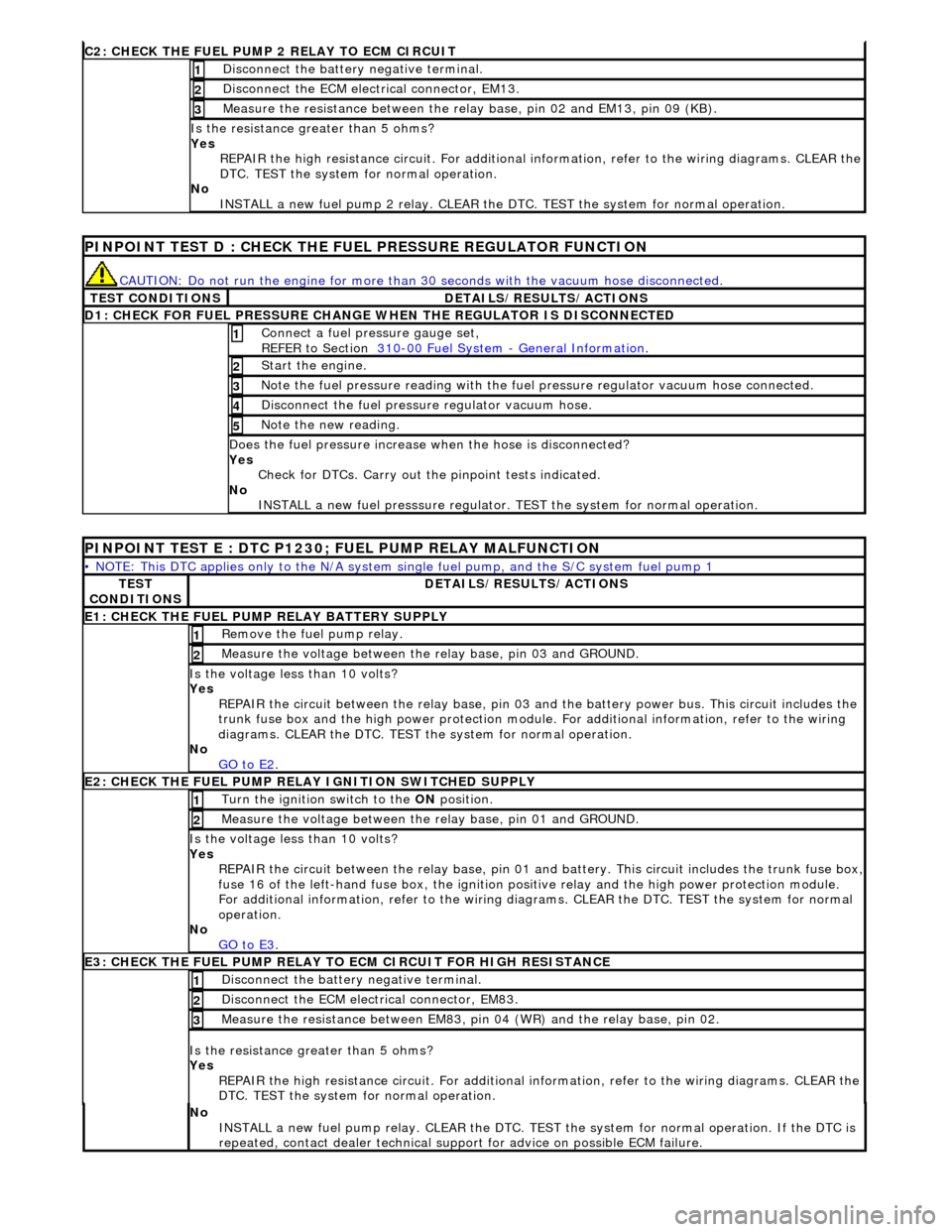
C2: CHECK THE FUEL
PUMP 2 RELAY TO ECM CIRCUIT
Di
sconnect the battery negative terminal.
1
D
isconnect the ECM electrical connector, EM13.
2
Meas
ure the resistance between the rela
y base, pin 02 and EM13, pin 09 (KB).
3
Is th
e resistance greater than 5 ohms?
Yes REPAIR the high resistance circuit. For additional information, refer to the wiring diagrams. CLEAR the
DTC. TEST the system for normal operation.
No INSTALL a new fuel pump 2 relay. CLEAR the DT C. TEST the system for normal operation.
P
INPOINT TEST D : CHECK THE FUEL PRESSURE REGULATOR FUNCTION
CAUTI
ON: Do not run the engine for more than
30 seconds with the vacuum hose disconnected.
T
EST CONDITIONS
D
ETAILS/RESULTS/ACTIONS
D
1: CHECK FOR FUEL PRESSURE CHANGE
WHEN THE REGULATOR IS DISCONNECTED
Connect a
fuel pressure gauge set,
REFER to Section 310
-00
Fuel System
-
General Informati
on
. 1
St
art the engine.
2
N
ote the fuel pressure readin
g with the fuel pressure regu lator vacuum hose connected.
3
Di
sconnect the fuel pressu
re regulator vacuum hose.
4
N
ote the new reading.
5
Doe
s the fuel pressure increase when the hose is disconnected?
Yes Check for DTCs. Carry out the pinpoint tests indicated.
No INSTALL a new fuel presssure regulator. TEST the system for normal operation.
P
INPOINT TEST E : DTC P1230;
FUEL PUMP RELAY MALFUNCTION
•
NOTE: This DTC applies only to the N/A system si
ngle fuel pump, and the S/C system fuel pump 1
TE
ST
CONDITIONS
D
ETAILS/RESULTS/ACTIONS
E1
: CHECK THE FUEL PUMP
RELAY BATTERY SUPPLY
R
emove the fuel pump relay.
1
Meas
ure the voltage between the
relay base, pin 03 and GROUND.
2
Is th
e voltage less than 10 volts?
Yes REPAIR the circuit between the rela y base, pin 03 and the battery power bus. This circuit includes the
trunk fuse box and the high power protection module . For additional information, refer to the wiring
diagrams. CLEAR the DTC. TEST th e system for normal operation.
No GO to E2
.
E2
: CHECK THE FUEL PUMP RELAY IGNITION SWITCHED SUPPLY
Turn the ignition swi
tch to the
ON position.
1
Meas
ure the voltage between the
relay base, pin 01 and GROUND.
2
Is th
e voltage less than 10 volts?
Yes REPAIR the circuit between the rela y base, pin 01 and battery. This circuit includes the trunk fuse box,
fuse 16 of the left-hand fuse box, the ignition po
sitive relay and the high power protection module.
For additional information, refer to the wiring diagrams. CLEAR the DTC. TEST the system for normal
operation.
No GO to E3
.
E3
: CHECK THE FUEL PUMP RELAY TO
ECM CIRCUIT FOR HIGH RESISTANCE
Di
sconnect the battery negative terminal.
1
D
isconnect the ECM electrical connector, EM83.
2
Meas
ure the resistance between EM83, pi
n 04 (WR) and the relay base, pin 02.
3
Is th
e resistance greater than 5 ohms?
Yes REPAIR the high resistance circuit. For additional information, refer to the wiring diagrams. CLEAR the
DTC. TEST the system for normal operation.
No
INSTALL a new fuel pump relay. CLEAR the DTC. TEST the system for normal operation. If the DTC is
repeated, contact dealer technical support for advice on possible ECM failure.
Page 1164 of 2490
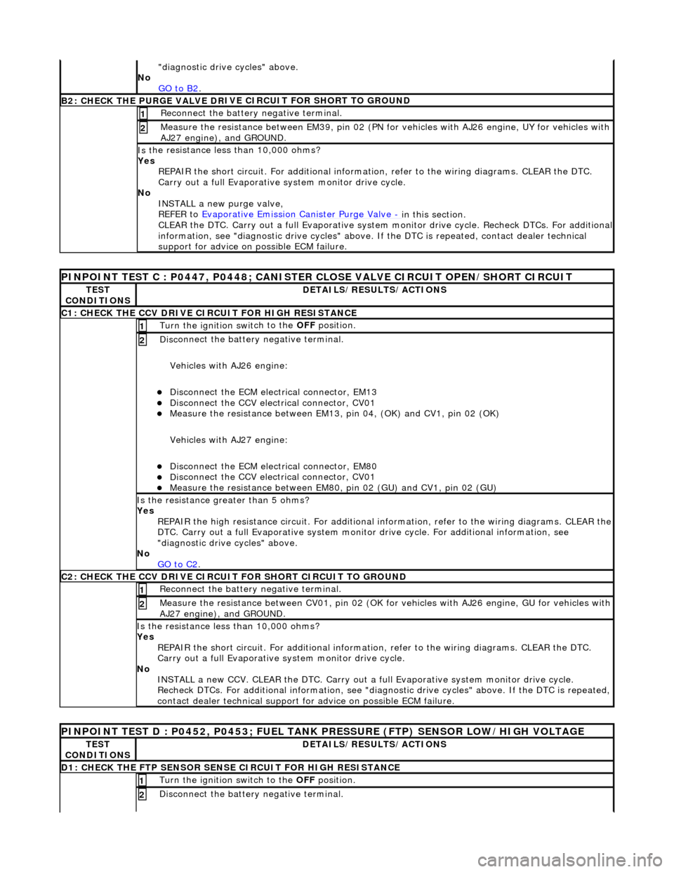
"d
iagnostic drive cycles" above.
No GO to B2
.
B2: CHECK THE PURGE VALVE DR
IV
E CIRCUIT FOR SHORT TO GROUND
Re
connect the battery negative terminal.
1
Meas
ure t
he resistance between EM39, pin 02 (PN for vehicles with AJ26
engine, UY for vehicles with
AJ27 engine), and GROUND.
2
Is t
he resistance less than 10,000 ohms?
Yes REPAIR the short circuit. For addi tional information, refer to the wiring diagrams. CLEAR the DTC.
Carry out a full Evaporative system monitor drive cycle.
No INSTALL a new purge valve,
REFER to Evaporative Emission Canister Purge Valve
- in thi
s section.
CLEAR the DTC. Carry out a full Evaporative system monitor drive cycle. Recheck DTCs. For additional
information, see "diagnostic drive cycles" above. If the DTC is repeated, contact dealer technical
support for advice on possible ECM failure.
PI
NPOINT TEST C : P0447, P0448; CANISTER CLOSE VALVE CIRCUIT OPEN/SHORT CIRCUIT
TE
S
T
CONDITIONS
D E
TAILS/RESULTS/ACTIONS
C1
: CH
ECK THE CCV DRIVE CIRCUIT FOR HIGH RESISTANCE
Turn the ignition swi
t
ch to the
OFF position.
1
Disc
onnect the battery negative terminal.
Vehicles with AJ26 engine:
Disc onne
ct the ECM electrical connector, EM13
Di
sc
onnect the CCV electrical connector, CV01
Meas
ure t
he resistance between EM13, pi
n 04, (OK) and CV1, pin 02 (OK)
Vehicles with AJ27 engine:
Disc onne
ct the ECM electrical connector, EM80
Di
sc
onnect the CCV electrical connector, CV01
Meas
ure t
he resistance between EM80,
pin 02 (GU) and CV1, pin 02 (GU)
2
Is the res
istance greater than 5 ohms?
Yes REPAIR the high resistance circuit. For additional information, refer to the wiring diagrams. CLEAR the
DTC. Carry out a full Evaporative system monitor drive cycle. For additional information, see
"diagnostic drive cycles" above.
No GO to C2
.
C2: CH
ECK THE CCV DRIVE CIRCUI
T FOR SHORT CIRCUIT TO GROUND
Re
connect the battery negative terminal.
1
Meas
ure t
he resistance between CV01,
pin 02 (OK for vehicles with AJ26 engine, GU for vehicles with
AJ27 engine), and GROUND.
2
Is t
he resistance less than 10,000 ohms?
Yes REPAIR the short circuit. For addi tional information, refer to the wiring diagrams. CLEAR the DTC.
Carry out a full Evaporative system monitor drive cycle.
No INSTALL a new CCV. CLEAR the DTC. Carry out a fu ll Evaporative system monitor drive cycle.
Recheck DTCs. For additional inform ation, see "diagnostic drive cycles" above. If the DTC is repeated,
contact dealer technical support for advice on possible ECM failure.
P INPOINT TES
T D : P0452, P0453; FUEL TANK
PRESSURE (FTP) SENSOR LOW/HIGH VOLTAGE
TES
T
CONDITIONS
DE
TAILS/RESULTS/ACTIONS
D
1:
CHECK THE FTP SENSOR SENSE CIRCUIT FOR HIGH RESISTANCE
Turn the ignition swi
t
ch to the OFF
position.
1
Disc
onnect the battery negative terminal.
2
Page 1192 of 2490
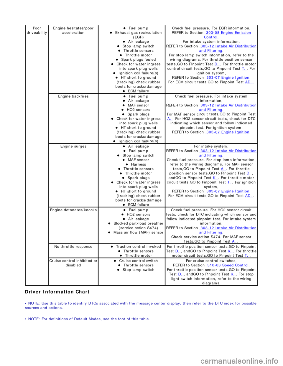
Driver Information
Chart
•
NOTE: Use this table to identify DTCs associated with the me
ssage center display, then refer to the DTC index for possible
sources and actions.
• NOTE: For definitions of Default Modes, see the foot of this table.
Poor
dr iveabilityEngine h e
sitates/poor
acceleration
Fue l
pump
Exhaus
t gas
recirculation
(EGR)
Air leakage Stop lamp swi t
ch
Throttl
e
sensors
Throttl
e
motor
Spark
plugs
fouled
Check f
o
r water ingress
into spark plug wells
Ignition coil fail
ure(s)
HT sh
o
rt to ground
(tracking) check rubber
boots for cracks/damage
ECM failu r
e
Check f
u
el pressure. For EGR information,
REFER to Section 303
-08 En gin
e Emission
Control.
F or i
ntake system information,
REFER to Section 303
-1 2
Intake Air Distribution
and F
ilt
ering
.
F or stop l
amp switch in
formation, refer to the
wiring diagrams. For throttle position sensor
tests,GO to Pinpoint Test D.
. Fo
r throttle motor
control circuit tests,GO to Pinpoint Test T.
. For
igni t
ion system,
REFER to Section 303
-07 En
gine Ignition
.
F or ECM
circuit tests,GO to Pinpoint Test
AD.
.
Engine backfiresFuel
pump
Air leakage MAF se
nsor
HO2 sensors
Spark plugs Check fo
r water ingress
into spark plug wells
HT sh o
rt to ground
(tracking) check rubber
boots for cracks/damage
Ignition coil fail
ure(s)
Chec
k fu
el pressure. For intake system
information,
REFER to Section 303
-12
Intake Air Distribution
and Filt
ering
.
F or MAF sensor ci
rcuit test
s,GO to Pinpoint Test
A.
. F or HO2 sensor
circui
t tests, check for DTC
indicating which sensor and follow indicated pinpoint test. For ignition system,
REFER to Section 303
-07 En
gine Ignition
.
Engine
s
urges
Air leakage
Fuel
pump
Stop lamp swit
ch
MAF s
e
nsor
Harness Throttl
e
sensors
Throttl
e
motor
Spark plugs
Check fo
r water ingress
into spark plug wells
HT sh o
rt to ground
(tracking) check rubber
boots for cracks/damage
ECM failu r
e
Fo
r
intake system,
REFER to Section 303
-1 2
Intake Air Distribution
and Filt
ering
.
Check fu
el pressure. For
stop lamp information,
refer to the wiring diagrams. For MAF sensor tests,GO to Pinpoint Test A.
. Fo
r throttle
position sensor tests,GO to Pinpoint Test D.
,
a n
dGO to Pinpoint Test
K.
. Fo
r throttle motor
circuit tests,GO to Pinpoint Test T.
. For ig
nition
system,
REFER to Section 303
-07 En
gine Ignition
.
F or ECM
circuit tests,GO to Pinpoint Test
AD.
.
Engine detonates/k
nocks
Fue
l
pump
HO2 sensors
Air leakage Blocked part-load breather
(s
ervice action S474)
Mass ai
r fl
ow (MAF) sensor
Chec
k fu
el pressure. Fo
r HO2 sensor circuit
tests, check for DTC indicating which sensor and
follow indicated pinpoint test. For intake system
information,
REFER to Section 303
-1 2
Intake Air Distribution
and Filt
ering
.
Check service action S474
. For MAF sensor
tests,GO to Pinpoint Test A.
.
No t
hrottle response
Traction contr
o
l invoked
Throttl
e
sensors
Throttl
e
motor
Fo
r th
rottle position sensor tests,GO to Pinpoint
Test D.
, andG O to Pinpoint
Test
K.
. Fo
r throttle
motor circuit tests,GO to Pinpoint Test T.
.
Cru i
se control inhibited or
disabled
Cru i
se control switch
Throttle
sensors
Stop lamp swit
ch
For cru
i
se control switches,
REFER to Section 310
-03
Speed Control
.
For th
rottle position sensor tests,GO to Pinpoint
Test D.
, andG O to Pinpoint
Test
K.
. For s t
op
light switch information, refer to the wiring diagrams.