1998 JAGUAR X308 Electronic engine controls
[x] Cancel search: Electronic engine controlsPage 15 of 2490

Superchar
ger
Outlet Pipe (18.50.16)
Supercharger Outlet Pipe Gasket (18.50.17)
Throttle Body Elbow (19.70.28)
Throttle Body Elbow Gasket (19.70.29)
303‐13: Evaporative Emissions
Diagnosis and Testing
Evaporative Emissions
Preliminary
Inspection
Diagnostic
Drive Cycles
Diagnostic
Trouble Code (DTC) index/Symptom Chart
Pinpoint
Tests
Removal
and Installation
Evaporative
Emission Canister (17.15.13)
Evaporative
Emission Canister Purge Valve (17.15.30)
Fuel
Tank Press
ure Sensor (19.55.31)
Fuel
Vapor Vent Valve Housing (19.55.24)
Fuel
Vapor Vent Valve Housing Seal (19.55.25)
303
‐14: Electronic Engine Controls
Description
and
Diagnosis
and Testing
Electronic
Engine Con
trols
Inspection
and Verification
Driver
Information Chart
Default
mode Definitions
Diagnostic
Trouble Code (DTC) Index
Pinpoint
Tests
Removal
and Installation
Catalyst
Monitor Sensor LH (18.30.81)
Catalyst
Monitor Sensor RH (18.30.80)
Heated Oxygen Sensor (HO2S) LH (18.30.79)
Heated Oxygen Sensor (HO2S) RH (18.30.78)
Camshaft
Position
Sen s
or
ECM
Position
Sensor
Crankshaft
Removal
Engine
Coolant Temperature
Sensor
Operation
Intake Air Temperature (IAT) Sensor (18.
30.52)
Page 43 of 2490

Safety Standard
Canister PurgeCANPControls pu
rging of the EVAP canister
Carbon dioxideCO2Colorless gas with
a density of a
pproximately 1.5 ti mes that of air
Carbon mon
oxide
COPoi
sonous gas produced as the re
sult of incomplete combustion
Case G
round
CSE GNDControl modu
le casing ground
Catal
ytic converter
In
-line exhaust system device used to reduce the level of engine exhaust
emissions
Ce
lsius
CSI ter
m for the Centigrade scale, with
freezing point at zero and boiling point
at 100°
Central
Processor Unit
CPUTh
e section of a computer that contai
ns the arithmetic, logic and control
circuits. It performs arithm etic operations, controls instruction processing, and
provides timing signals and other housekeeping operations
Cl
osed Loop
CL
Cl
osed Loop System
CLSControl
system with one
or more feedback loops
Col
umn/Mirror Control
Module
C/MC
M
Control ModuleCMA
self-contained group of electrical/electronic components, designed as a
single replaceable un it, and controlling one or more processes
Controll
er Area Network
CANA
communication system which allows control modules to be linked together
in a network.
Crankshaft Posi
tion
Sensor
CKPSGenerates crankshaft positi on informa
tion in conjunct
ion with the CKPTR (also
generates speed information in certain applications)
Crankshaft Posi
tion
Timing Ring
CKPT
R
Toothe
d ring which
triggers the CKPS
Crankcase Ventila
tion
System
CVSys
tem which scavenges camshaft cover and crankcase emissions and feeds
them into the inlet manifold
Cubic ce nt
imeter
cm
3
Curb weightWe
ight of vehicle with fuel, lubrican
ts and coolant, but excluding driver,
passengers or payload
D
Dat
a Link Connector
DLCConne
ctor providing access and/or control of the vehicle information,
operating conditions, and diagnostic information
De
gree
deg, °Angle or tempe
rature
D
epartment of
Transportation (US)
DO
T
D
epartment of Transport
(UK)
DTp
De
utsche In
stitut für
Normung
DINGerman stand
ards regulation body
Di
agnostic Module
DMSuppl
emental Restraint System (non-c
ontrolling) module for diagnostics
overview
Di
agnostic Test Mode
DTMA le
vel of capability in an OBD system.
May include different functional states
to observe signals, a base level to re ad DTCs, a monitor level which includes
information on signal levels, bi-directional control with on /off board aids, and
the ability to interface with remote diagnosis
Diagnostic Trouble CodeDTCAn al
pha/numeric identifier for a fault
condition identified by the On-Board
Diagnostic (OBD) system
D
ial test indicator
DTIA mechan
ical measuring
instrument, with a rotary indicating pointer
connected to a linear operating probe
D
ifferential pressure
Pressure di
fference betwee
n two regions e.g. between intake manifold and
atmospheric pressures
D
ifferential Pressure
Feedback EGR
DP
FE
An
EGR system that monito
rs differential EGR pressure across a remote orifice
to control EGR flow
D
irect current
dcCurrent which f
lows in on
e direction only, though it may have appreciable
pulsations in its magnitude
Du
al linear switch
DLSJ
-gate switch connected to the TCM on SC vehicles
E
EGR
Temperature EGRT
Sensor
EGRTSens
ing EGR function based on temperature change
EGR Vacu
um Regulator
EVRControls EGR
flow by changi
ng vacuum to the EGR valve
EGR Valve
Position
EVPAn EGR
system that direct
ly monitors EGR valve position to control EGR flow
Electrically E
rasable
Programmable Read-Only
Memory
EEP
ROM
Page 47 of 2490

Mem
ory
Pulse Width ModulationPW
M
A
method of control in an electronic co
ntrol system in which the duration of
pulses in a pulse train is proportional to the amplitude of the modulating
signal
R
Ran
dom Access Memory
RAMF
ast access memory store which is accessible for entry or extraction of data
Re
ad-Only Memory
RO
M
F
ast access memory in which data
is fixed and may not be changed
Re
servoir
RESContaine
r, usually for oils,
coolants or hydraulic fluids
Re
turn
RTNA
dedicated sensor ground circuit
R
evolutions Per Minute
RP
M
Shaft speed o
f a device, us
ually an engine or motor
R
ight-hand
RH
Right-hand drive veh
icle
RHD
S
Scan T
ool
STDe
vice that interfaces with and comm
unicates information on a data link
Se
at Control Module
SCMModule
controlling the seat motor systems (not electric raise/lower-only
seats)
Secon
dary Air
Air pro
vided to the exhaust system
Secon
dary Air Injection
AIRSy
stem used for a period of time each
time the engine is started, unless
certain temperature criter ia are met. Pumps air directly into the exhaust
system which generates extra heat and reduces the time taken for the
catalytic converters to reach operating temperature
Secon
dary Air Injection
Bypass
AIRBVents secon
dary air to atmosphere
Secon
dary Air Injection
Check Valve
AIRCValve wh
ich prevents back-flow of exhaust gas to the AIR system when the
system is inoperative
Secon
dary Air Injection
Diverter
AIRDD
iverts secondary air to either
the catalyst or exhaust manifold
Secon
dary Air Injection
Magnetic Clutch
AIRP
C
Clu
tch mounted on the AIRP drive shaft
Secon
dary Air Injection
Pump
AIRPMe
chanically driven rotary vane
pump, driven through the AIRPC
Secon
dary Air Injection
Relay
AIRRCont
rols the injection of air into the exhaust system
Secon
dary Air Injection
Switchin
g Va
lve
AIRSV
acuum operated valve backing-up the AIRC
Secu
rity and Locking
Control Module
SLCMModul
e controlling the vehicle's security and closure-locking functions
SensorSGeneri
c name for a device
that senses either the absolute value or a change
in a physical quantity su ch as temperature, pressure or flow rate, and
converts that change into an electrical quantity signal
Servic
e Repair Operation
(number)
SRONu
mber generated by Jaguar Methods
and Techniques system which relates
to the time allowed to complete a repair operation. Further information on the
system can be found in the separate Jaguar Publications (for each model
range) entitled 'Repair Operation Times'
Shif
t signal
SDA
shift process signal to the TCM on SC vehicles
Shif
t Solenoid
SSControls shi
fting in an automatic transmission
Si
gnal return
SIG RTN
Slidin
g Roof Control
Module
SRCM
Society of Automotive
Engineers
SAE
Speed
Control Control
Module
SCCMModule con
trolling Speed Control System
Square c
entimeter
cm
2
Stan
dard
std
Stan
dard Corporate
Protocol
SCPA
high-speed, serial communications system linking all body system control
modules. Control messages and data ar e passed between modules at up to
786 messages per second
SuperchargerSCAn in
take system which utilizes a supercharger (mechanically driven device
that pressurizes intake air, thereby in creasing density of charge air and the
consequent power output from a given displacement)
Supercharger
Bypass
SCB
SwitchSW
T
Page 48 of 2490

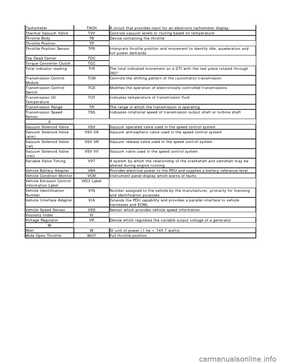
Tacho
meter
TACHA
ci
rcuit that provides input for
an electronic tachometer display
Thermal Vacuu
m Valve
TVVControls vacuum l
e
vels or
routing based on temperature
Throttle
Body
TBDe
vi
ce containing the throttle
Throttl
e
Position
TP
Throttl
e
Position Sensor
TPSInterprets throttl
e
position and movement to iden tify idle, acceleration and
full-power demands
Top Dead CenterTDC
Torque Converter C
lutch
TCC
To
tal
indicator reading
TIRThe t
o
tal indicated movement on a DTI with the test piece rotated through
360°
Transm
ission Control
Module
TCMControls
the shifting pattern
of the (automatic) transmission
Transm
ission Control
Switch
TCSModifi es
the operation of electronically controlled transmissions
Transmission Oil
TemperatureTOTIndi
cat
es temperature of transmission fluid
Transmission RangeTRThe ran
g
e in which the transmission is operating
Transmission Spe
e
d
Sensor
TSSIndi cat
es rotational speed of transmission output shaft or turbine shaft
V
Vacuu
m
Solenoid Valve
VSVVacuu
m
operated valve used in the speed control system
Vacuu
m
Solenoid Valve
(atm)
VSV VAVacuu m
atmospheric valve used in the speed control system
Vacuu
m
Solenoid Valve
(rel)
VSV VRVacuu m
release valve used in the speed control system
Vacuu
m
Solenoid Valve
(vac)
VSV VVVacuu m
valve used in the speed control system
Variable Valve TimingVVTA
s
ystem by which the relationship of the crankshaft and camshaft may be
altered during engine running
Vehi cl
e Battery Adapter
VBAProvide
s
electrical power to the PDU
and supplies a battery reference level
Vehicl
e Condition Monitor
VCMInst
rum
ent panel display which warns of faults
Ve
hic
le Emission Control
Information Label
VECI Label
Vehi cl
e Identification
Number
VINN u
mber assigned to the vehicle by the manufacturer, primarily for licensing
and identification purposes
Vehi cl
e Interface Adapter
VIAExtends the
PDU ca
pability and provid
es a parallel interface to vehicle
harnesses and ECMs
Vehicle Spe e
d Sensor
VSSSens
or which provides ve
hicle speed information
Viscosity In
dexVI
Voltage RegulatorVRDe
vice which regulates the variable output voltage of a generator
W
Wat
tWSI unit of power (1 hp = 7
45.7 watts)
W
i
de Open Throttle
WO
TFu
ll throttle position
Page 522 of 2490

diverter val
ve (if fitted) and oil filter.
Main
bearings
which are grooved in the upper positions and plain in
the lower positions. They are manufactured from
aluminium / tin material.
A c
rankshaft with under
cuts and rolled fillets for extra strength.
Fracture
-split connecting rods in sintered-forged steel.
Brackets
bolted to the front of
the cylinder
block are used to mo unt all accessories.
A sin
gle, seven ribbed vee belt
drives the accessories.
An au
tomatic belt tensioner for the front accessory drive,
incorporating a wear indicator.
An advanced en
gine management system inco
rporating electronic throttle control.
The un
it meets the requirements of the CARB OBDII USA legislation.
Ancillary Systems
The an
ci
llary systems, driven by the engine, each have a
detailed Description and Operation along with Diagnostic
Procedures, and Removal and Installation instructions ; refer to the following sections of this manual:
Power Steeri
ng Pump - Section 211-02
Ai
r Conditioning Compressor - Sectio
n 412-03
Engine
C
ooling Pump - Section 303-03
Generator
- Sectio
n 414-02
The drive belt, idler pulley and automatic tensioner are described in Section 303-05.
The engine starting system is described in Section 303-06.
En
gine Management and Emission Control System
Engine Control Modu
le (ECM)
Engine
management and exhaust emissions are controlled by the ECM, which has the
following main functions:
Fu
el injection
Idle
s
peed
Ignition Ev
aporative loss system
Engine
cooling fans Clim
ate control compressor clutch demand
The microprocessor within the ECM receiv es signals from various sensors and other modules and uses a pre-determined
program to compute engine management functions.
Adaptive functions are incorporated in the ECM to cater for co ntinuous adjustments to its computations to suit prevailing
conditions. Because the system also controls emissions to suit all modes, neither CO levels nor idle speed require service
attention or adjustment, except if an error should occur.
On Board Diagnostics are controlled by the ECM with the continuous monitoring of incoming signals and the subsequent
verification against what the module expects to 'see'. Should a si gnal be incorrect or missing, the ECM will substitute a fixed
value to provide the 'limp home mode' and alert the driver of the problem. Fixed values may be adopted for:
Transmission oil
temperature
Mechanica
l
guar
d position
Throttle blade angle Camshaft position
Inta
k
e air temperature
Diagnostic trouble codes (DTC), including OBD II codes, are stored in the ECM memo ry and can be read by an appropriate
retrieval tool.
Should either the ECM or TCM fa il, ensure that the control housing cooling fan is operating correctly. Failure of the cooling
fan MUST be rectified before renewing a control module and details of a fa n failure should accompany a returned control
module.
Page 527 of 2490

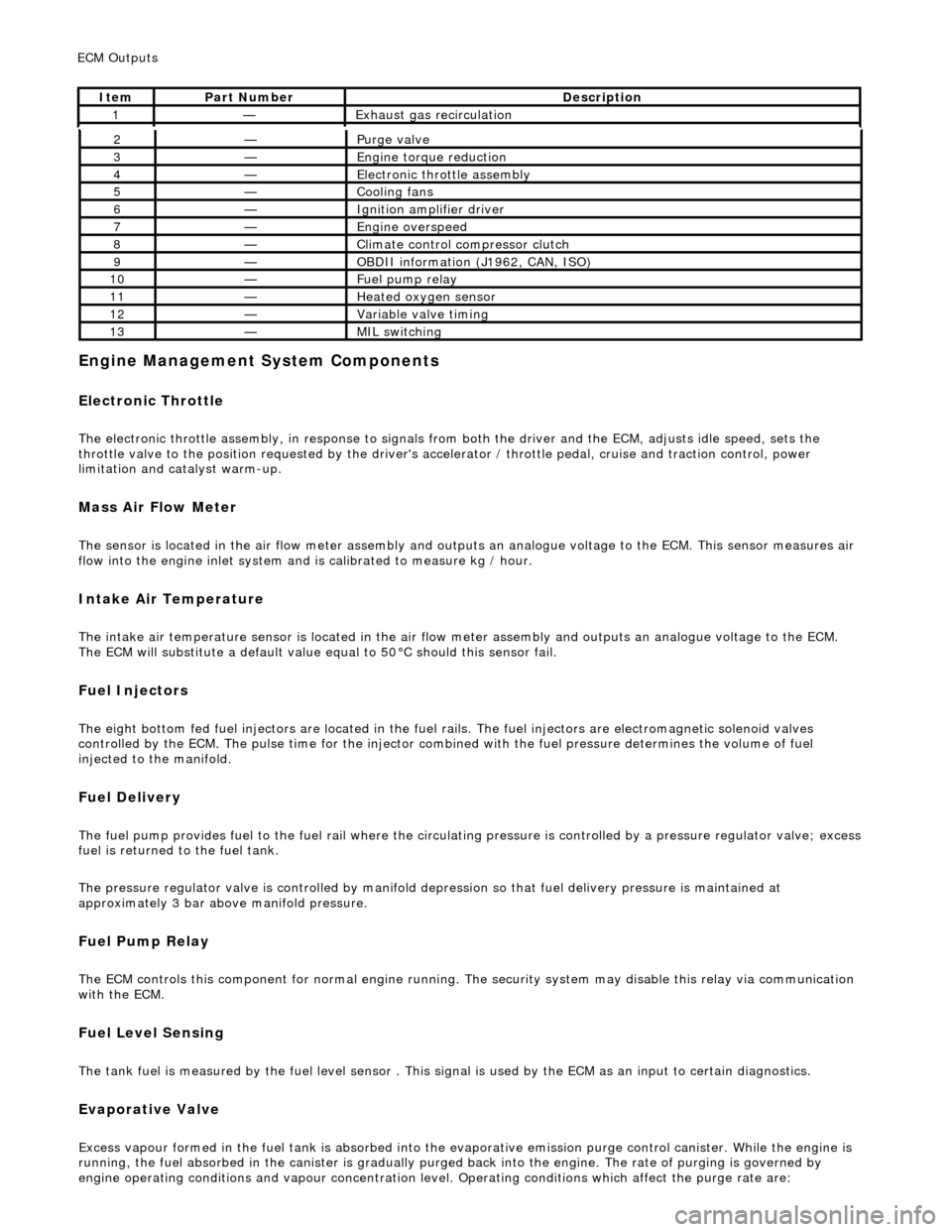
E
ngine Management System Components
Electronic Throt
tle
The
electronic throttle assembly, in resp
onse to signals from both the driver and the ECM, adjusts idle speed, sets the
throttle valve to the position requested by the driver's accelerator / throttle pedal, cruise and traction control, power
limitation and catalyst warm-up.
Mass
Air Flow Meter
The sensor i
s located in the air flow mete
r assembly and outputs an analogue voltag e to the ECM. This sensor measures air
flow into the engine inlet system and is calibrated to measure kg / hour.
In
take Air Temperature
Th
e intake air temperature sensor is loca
ted in the air flow meter assembly and outputs an analogue voltage to the ECM.
The ECM will substitute a default value eq ual to 50°C should this sensor fail.
Fuel Injectors
The eigh
t bottom fed fuel injectors are located in the fuel rails. Th
e fuel injectors are electromagnetic solenoid valves
controlled by the ECM. The pulse time for the injector combined with the fuel pr essure determines the volume of fuel
injected to the manifold.
Fue
l Delivery
The fu
el pump provides fuel to the fuel rail where the circulat
ing pressure is controlled by a pressure regulator valve; excess
fuel is returned to the fuel tank.
The pressure regulator valve is controlled by manifold depression so that fuel delivery pressure is maintained at
approximately 3 bar above manifold pressure.
Fuel Pump
Relay
The ECM controls thi
s component for normal
engine running. The security system may disable this relay via communication
with the ECM.
Fuel Lev
el Sensing
The tank fuel
is measured by the fuel le
vel sensor . This signal is used by the ECM as an in put to certain diagnostics.
Eva
porative Valve
Excess vapour
formed in the fuel tank is
absorbed into the evaporative emission pu rge control canister. While the engine is
running, the fuel absorbed in the canister is gradually purged back into the engine. The rate of purging is governed by
engine operating conditions and vapour concentration level. Operating conditions which affect the purge rate are:
2—Purge
valve
3—Engine
torque reduction
4—E
lectronic throttle assembly
5—Coo
ling fans
6—Ignition amplifier driver
7—Engine overspeed
8—Cli
mate control compressor clutch
9—O
BDII information (J1962, CAN, ISO)
10—F
uel pump relay
11—Heat
ed oxygen sensor
12—Vari
able valve timing
13—MIL sw
itching
ECM Out
puts
It
em
Par
t Number
De
scription
1—Exhaus
t gas recirculation
Page 1022 of 2490

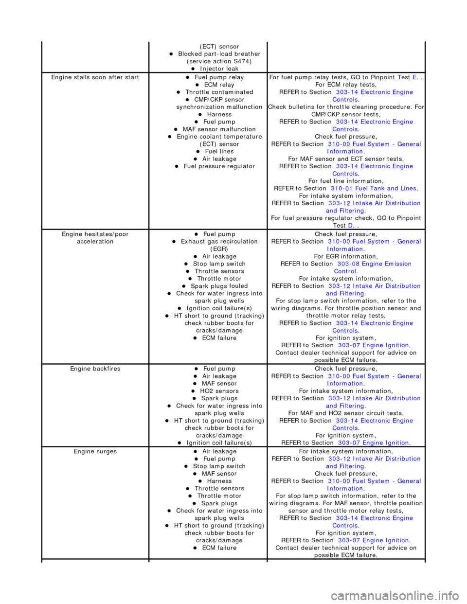
(ECT) se
nsor
Blocked part-load breather
(s
ervice action S474)
Injec
t
or leak
Engine stalls
soon
after start
F
u
el pump relay
ECM relay Thr
o
ttle contaminated
CMP/CKP sen
s
or
synchronization malfunction
Harness Fuel
pump
MAF
s
ensor malfunction
Engine coolan
t
temperature
(ECT) sensor
Fue l
lines
Air leakage Fu
el pressure regulator
F
o
r fuel pump relay tests,
GO to Pinpoint Test E.
.
F or ECM
relay tests,
REFER to Section 303
-14 Elec tronic En
gine
Controls.
Check bull etins for throttl
e cleaning procedure. For
CMP/CKP sensor tests,
REFER to Section 303
-14 Elec tronic En
gine
Controls.
Chec k fu
el pressure,
REFER to Section 310
-00 Fu
el System
- Ge
n
eral
Informati
o
n
.
F or MAF sensor and
ECT sensor tests,
REFER to Section 303
-14 Electronic En
gine
Controls.
For fuel l
ine information,
REFER to Section 310
-01
Fuel Tank and Lines
.
F or i
ntake system information,
REFER to Section 303
-1 2
Intake Air Distribution
and F
ilt
ering
.
F o
r fuel pressure regulato
r check, GO to Pinpoint
Test D.
.
Engine h e
sitates/poor
acceleration
Fue l
pump
Exhaus
t gas
recirculation
(EGR)
Air leakage Stop lamp swi t
ch
Throttl
e
sensors
Throttl
e
motor
Spark plugs
fouled
Check f
o
r water ingress into
spark plug wells
Ignition coil fail
ure(s)
HT sho
rt to ground (tracking)
check rubber
boots for
cracks/damage
ECM failu r
e
Chec
k fu
el pressure,
REFER to Section 310
-00 Fu
el System
- Ge
n
eral
Informati
o
n
.
F o
r EGR information,
REFER to Section 303
-08 En gin
e Emission
Control.
F or i
ntake system information,
REFER to Section 303
-1 2
Intake Air Distribution
and F
ilt
ering
.
F or stop l
amp switch in
formation, refer to the
wiring diagrams. For throttle position sensor and throttle motor relay tests,
REFER to Section 303
-14 Elec tronic En
gine
Controls.
For ign i
tion system,
REFER to Section 303
-07 En
gine Ignition
.
Contact dealer techn i
cal
support for advice on
possible ECM failure.
Engine ba ckfiresFuel
pump
Air leakage MAF s
e
nsor
HO2 sensors Spark plugs
Check fo
r water ingress into
spark plug wells
HT short to ground (tracking) check rubber
boots for
cracks/damage
Ignition coil fail
ure(s)
Chec
k fu
el pressure,
REFER to Section 310
-00 Fu
el System
- Ge
n
eral
Informati
o
n
.
F or i
ntake system information,
REFER to Section 303
-1 2
Intake Air Distribution
and F
ilt
ering
.
For MAF and HO2
sensor circuit tests,
REFER to Section 303
-14 Electronic En
gine
Controls.
For igni
tion system,
REFER to Section 303
-07 En
gine Ignition
.
Engine
s
urges
Air leakage Fue
l
pump
Stop lamp swi
t
ch
MAF s
e
nsor
Harness Throttl
e
sensors
Throttl
e
motor
Spark plugs
Check fo
r water ingress into
spark plug wells
HT sho rt to ground (tracking)
check rubber
boots for
cracks/damage
ECM failu r
e
F
or i
ntake system information,
REFER to Section 303
-1 2
Intake Air Distribution
and F
ilt
ering
.
Chec k fu
el pressure,
REFER to Section 310
-00 Fu
el System
- Gen
e
ral
Informati
o
n
.
F or stop l
amp switch in
formation, refer to the
wiring diagrams. For MAF se nsor, throttle position
sensor and throttle motor relay tests,
REFER to Section 303
-14 Elec tronic En
gine
Controls.
For ign i
tion system,
REFER to Section 303
-07 En
gine Ignition
.
Contact dealer techn i
cal
support for advice on
possible ECM failure.
Page 1025 of 2490

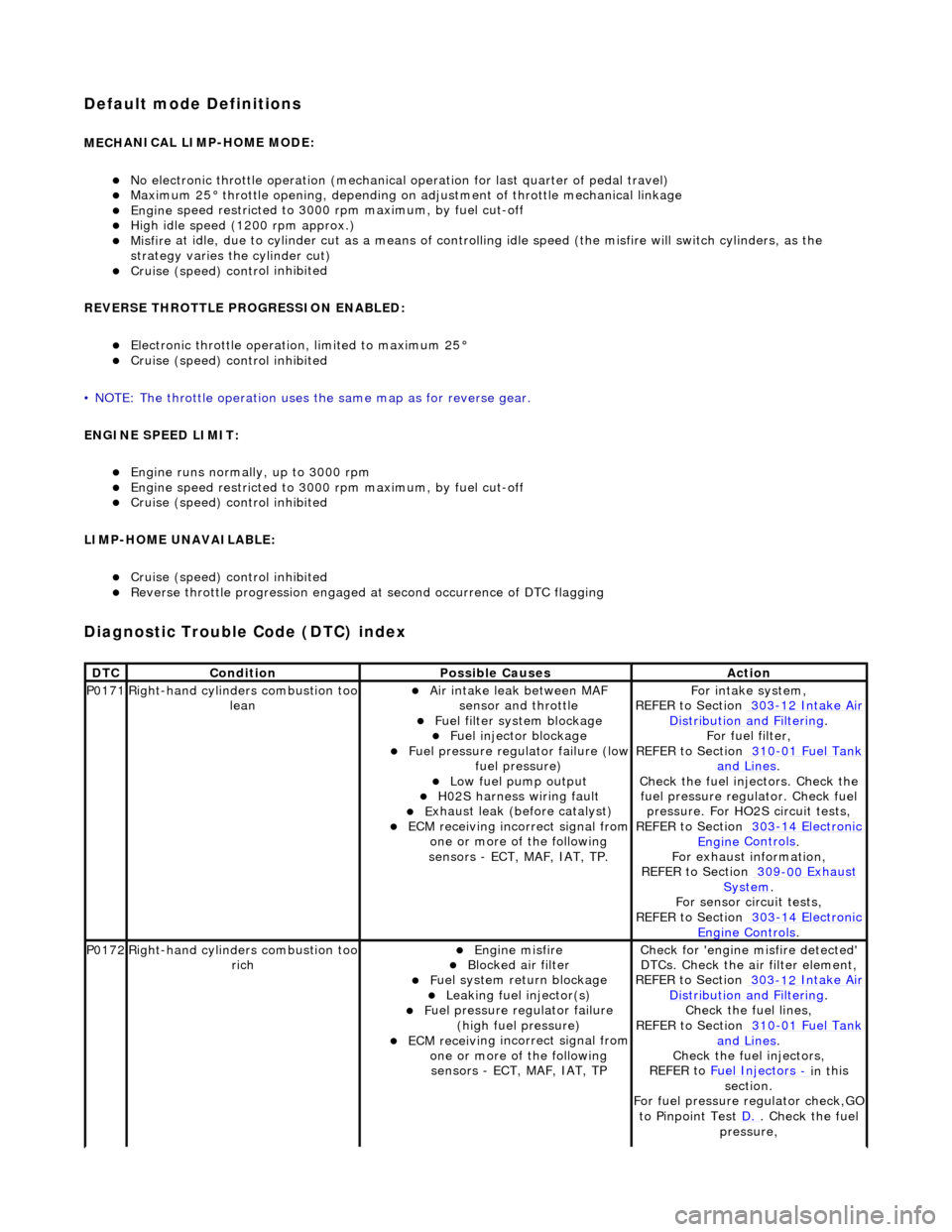
Default mode Definitions
MECH
ANICAL LIMP-HOME MODE:
No el
ectronic throttle operation (mechanical
operation for last quarter of pedal travel)
M
aximum 25° throttle opening,
depending on adjustment of th rottle mechanical linkage
Engine
speed restricted to 3000
rpm maximum, by fuel cut-off
Hi
gh idle speed (1200 rpm approx.)
Misfire
at idle, due to cylinder cut as a means of control
ling idle speed (the misfire will switch cylinders, as the
strategy varies th e cylinder cut)
Cruise (speed) contr
ol inhibited
REVERSE THROTTLE PROGRESSION ENABLED:
El
ectronic throttle operation, limited to maximum 25°
Cruise (speed) contr
ol inhibited
• NOTE: The throttle oper ation uses the same map as for reverse gear.
ENGINE SPEED LIMIT:
Engine
runs normally, up to 3000 rpm
Engine
speed restricted to 3000
rpm maximum, by fuel cut-off
Cruise (speed) contr
ol inhibited
LIMP-HOME UNAVAILABLE:
Cruise (speed) contr
ol inhibited
R
everse throttle pr
ogression engaged at second occurrence of DTC flagging
Diagnostic Trouble Code (D
TC) index
DT
C
Cond
ition
P
ossible Causes
Acti
on
P0171Right-hand cylinders combustion too
leanAir
intake leak between MAF
sensor and throttle
F
uel filter system blockage
F
uel injector blockage
F
uel pressure regulator failure (low
fuel pressure)
Low f
uel pump output
H0
2S harness wiring fault
E
xhaust leak (before catalyst)
ECM receivi
ng incorrect signal from
one or more of the following
sensors - ECT, MAF, IAT, TP.
Fo
r intake system,
REFER to Section 303
-12
Intake Air
Distribu
tion and Filtering
.
F
or fuel filter,
REFER to Section 310
-01
Fuel Tank
and Lines.
Chec
k the fuel injectors. Check the
fuel pressure regu lator. Check fuel
pressure. For HO2S circuit tests,
REFER to Section 303
-14
Electronic
Engine
Controls
.
F
or exhaust information,
REFER to Section 309
-00
Exhaust
Sy
stem
.
For se
nsor circuit tests,
REFER to Section 303
-14
Electronic
Engine
Controls
.
P0172Right-hand cylinders combustion too
ri
ch
Engine
misfire
Bl
ocked air filter
F
uel system return blockage
Leak
ing fuel injector(s)
F
uel pressure regulator failure
(high fuel pressure)
ECM receivi
ng incorrect signal from
one or more of the following sensors - ECT, MAF, IAT, TP
Chec
k for 'engine misfire detected'
DTCs. Check the air filter element,
REFER to Section 303
-12
Intake Air
Distribu
tion and Filtering
.
Chec
k the fuel lines,
REFER to Section 310
-01
Fuel Tank
and Lines.
Chec
k the fuel injectors,
REFER to Fuel Injectors
- in t
his
section.
For fuel pressure regulator check,GO
to Pinpoint Test D.
.
Check the fuel
pressure,