1998 JAGUAR X308 ad blue
[x] Cancel search: ad bluePage 1992 of 2490
The part number of the pre-terminated wiring harness The letter showing the extractor tip which must be used to remove this type of electrical connector terminal Those electrical connector terminals which are gold
Some of the pre-terminated wiring harness( s) have seals installed to the insulation for sealed connector applications. It is
essential for prevention of mo isture ingress that a sealed pre-terminated wiring harness must be used where a sealed
terminal was removed.
CAUTION: Where the repair procedure indica tes that a glue lined heat shrink sleeve should be applied, apply sufficient
heat to the glue lined heat shrink to melt the glue in order to provide a water tight seal. Do not over heat the glue lined
heat shrink sleeve so that the wiring harness insulation becomes damaged.
Two sizes of heat shrink sleeving are supplied in the wiring harn ess repair kit. Each heat shrink sleeve contains a sealant
glue. These must be used when connecting wiring harness(s) or electrical connector terminal(s) at all times. The smaller
diameter heat shrink sleeve is to be used with the red and blue butt splice connectors and the larger di ameter sleeve with
the yellow butt sp lice connectors.
For ease and speed, some of the pre-term inated wiring harness(s) may already have the insulation partly stripped at the
splice end. If the repair requires insula tion to be stripped from the cable, refer to the Relationship Table fo r the correct
length of insulation to be stripped.
The Pre-Terminated Wiring Harness(s) illu stration shows the electrical connector terminal type, the part number of the pre-
terminated wiring harness and the letter of the extractor tip which must be used to extract the electrical connector terminal
from the connector housing. Additionally, those electrical conne ctor terminal(s) which are gold are identified, all others are
therefore, tinned and not gold.
Wiring Harness Cable Identification Sleeves
A selection of colored sleeves are contai ned in the wiring harness repair kit for maintaining the wiring harness cable
identification on the pre-term inated wiring harness. Place the correct colo red sleeve(s) over the pre-terminated wiring
harness insulation as near to the electr ical connector as possible with the main wiring harness cable color nearest to the
electrical connector.
For example, if the original wiring harness cable color is pink with a black trace put the pink wiring harness cable
identification sleeve on the pre-terminated wiring harness first followed by a black sleeve, and slide both along the wiring
harness cable to the electr ical connector terminal.
Extraction Handle and Tips
The extraction handle, in conjunction with th e correct tip, is used to remove a terminal from an elec trical connector. Each tip contained in the wiring harness repair kit is marked with an identification letter, A to K inclusive. Each tip has been special ly
designed to extract a particular ty pe of electrical connector terminal. The use of any other tool is not recommended and is
liable to cause damage to the electrical connector. The tip is fastened to the handle by a screw which holds the tip firmly yet
allows it to be easily replaced.
Extraction Handle and Tips
Page 1995 of 2490
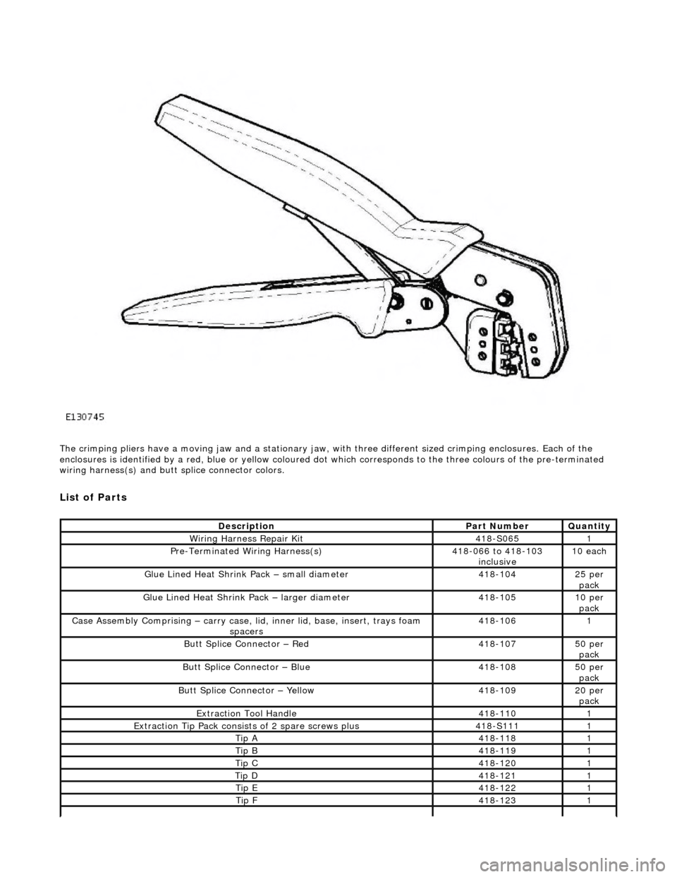
The crimping pliers have a moving jaw and a stationary jaw, with three different sized crimping enclosures. Each of the
enclosures is identified by a red, blue or yellow coloured dot which correspon ds to the three colours of the pre-terminated
wiring harness(s) and butt splice connector colors.
List of Parts
DescriptionPart NumberQuantity
Wiring Harness Repair Kit 418-S0651
Pre-Terminated Wiring Harness(s)418-066 to 418-103
inclusive 10 each
Glue Lined Heat Shrink Pack – small diameter418-10425 per
pack
Glue Lined Heat Shrink Pack – larger diameter418-10510 per pack
Case Assembly Comprising – carry case, li d, inner lid, base, insert, trays foam
spacers418-1061
Butt Splice Connector – Red 418-10750 per pack
Butt Splice Connector – Blue 418-10850 per
pack
Butt Splice Connector – Yellow 418-10920 per pack
Extraction Tool Handle 418-1101
Extraction Tip Pack consists of 2 spare screws plus 418-S1111
Tip A418-1181
Tip B418-1191
Tip C418-1201
Tip D418-1211
Tip E418-1221
Tip F418-1231
Page 1996 of 2490
Items can be ordered from:
SPX United Kingdom Limited
Ironstone Way
Brixworth
Northants
NN6 9UD
United Kingdom
Telephone: +44 (0) 1327 704461
Fax: +44 (0) 1327 706632
Repair Methods
CAUTION: Several different types and sizes of terminal may be found in a single electrical connector
housing.
It is necessary to identify:
The conductor (wire) size of the affected wiring harness The electrical connector range from which the damaged wiring harness is to be removed The terminal type
Use of the approved diagnostic tool will greatly assist in th e quick identification of electrical connectors and faulty pin
terminal(s).
Reference can also be made to the vehicle Electrical Guides, he ld by Dealers, to identify wiring harness(s) and electrical
connector(s).
By using the Relationship Table, the wiring harness conductor (wire) size can be related to a suitable pre-terminated wiring
harness by the color of the insulation. Also , the correct length of insulation to be stripped from the wiring harness lead is
identified.
Relationship Table
Electrical Connector Terminal Extraction
Tip G418-1241
Tip H418-1251
Tip I418-1261
Tip J418-1271
Tip K418-1281
Sleeve Identification Pa ck – for Red insulation418-112500
Sleeve Identification Pack – for Blue insulation 418-113500
Sleeve Identification Pack – for Yellow insulation 418-114500
Instruction Manual JTP 5931
Crimping Pliers YRW5000101
Wire Stripping Tool 418-1171
CABLE RANGE SPLICE STRIP LENGTH
0.35 mm² to 1.50 mm²RED6.00 to 7.00 mm
1.00 mm² to 2.50 mm²BLUE6.00 to 7.00 mm
4.00 mm² to 6.00 mm²YELLOW9.00 to 9.50 mm
Page 2002 of 2490
Repair Procedure
• CAUTIONS: Do not use crimping pliers, insulation strippers, butt splice connectors, heat sh rink sleeves or pre-terminated wiring
harness(s) that are not supplied with the Jagu ar wiring harness repair kit. Each part has been designed to be used only with
the other parts in this wiri ng harness repair kit.
Where the repair procedure indicates that a glue lined heat shrink sleeve should be applied, apply sufficient heat to
the glue lined heat shrink to melt the glue in order to provide a water tight seal. Do not
over heat the glue lined heat shrink sleeve so that the wiring harness insulation becomes damaged.
It is not correct to make more than five repair joints on the wiring harness to any electrical connector and if more damage is
found at the same electrical connector then a new wiring harness must be installed.
Remove the faulty terminal from the elec trical connector using the extractor tool and correct tip. Make sure that any
anti-backout device is released befo re trying to remove the terminal.
CAUTION: : A number of electrical connector terminals ar e gold plated or gold flashed. When defective, they
must be installed with a gold pre-terminated wiring harnes s(s) from the wiring harness repair kit. It is not always
easy to identify the female as gold but the male pins are visually easier, therefore always check both male and
female terminals to identify those which are gold. Under no circumstances are gold and tin terminals to be mixed as
this will lead to early failur e of the electrical contact.
• NOTE: Never use a harness lead with a smalle r diameter than the original harness lead.
Select the correct size and ty pe of pre-terminated wiring harness and butt splice connector from the wiring harness
repair kit.
Using the wire cutter on the stripping tool, cut the pre-terminated wiring harness and the harness cable to the
required length.
• NOTE: See illustration: Stripping Insulation
From the Relationship Table, find the correct length of insulation to be stripped from the pre-terminated wiring
harness and set the adjustable cable length stop to the correct length. Place the pre-terminated wiring harness in
the wire stripper and remove the insulation.
Put the cable identification sleeve(s) on to the wiring harness with the main cable colour nearest to the terminal. During this next step do not overtighten. Place the selected butt splice connector in the crimping tool, matching the
aperture and the butt connector colours. Make sure that the window indentation in the butt connector is resting over
the guide bar on the lower jaw. Partially close the grip until the butt connec tor is securely held in the aperture. This
will give support to the butt conn ector while the pre-terminated wiring harness is inserted into it.
• NOTE: See illustration: Spice Correctly Located
Insert the pre-terminated wiring harnes s into the butt connector and make sure that the wire is against the wire
stop. Close the grip firmly, crimping the lead to the butt connector. When the handles have been completely closed
the butt connector will be fre ed from the tool as the handles are released. If the handles have not been completely
closed then the jaws will hold the butt connector and it cannot be removed from the tool until the crimp is fully made
by closing the handles completely. Make sure that the harness cable has been squarely cut and the correct length of insulation removed. If more than
one splice is needed the butt connectors must be not be crimped to the wiring harness at the same distance from
the connector. The splices must be staggered to prevent a bulk of splices in the same area of the wiring harness.
It is preferable to cover the butt splice joint with heat shrink sleeve. This is desirable not essential, except where the
electrical connector is a sealed electrical connector. Use the smaller diameter sleeve for red and blue pre-terminated
wiring harness(s) and the large diameter sleeve for the yellow pre-terminated wiring harnes s(s). It is advisable to
place the heat shrink over the completed joint but in some instances the sleeve will not pass over the terminal.
Check, and if required, place the correct size sleeve onto the harness cable or pre-terminated wiring harness before
crimping the butt splice to the wiring harness.
Place the harness cable into the butt splice with the spli ce window over the guide bar. Make sure that the cable
harness wire is agains t the stop in the butt splice, crimp the butt splice connector to the wiring harness.
Gently pull the harness cables each side of the butt sp lice to make sure that a secure joint has been made.
AMP 6.3 flatDD
Econoseal III 250 seriesBF
Page 2221 of 2490
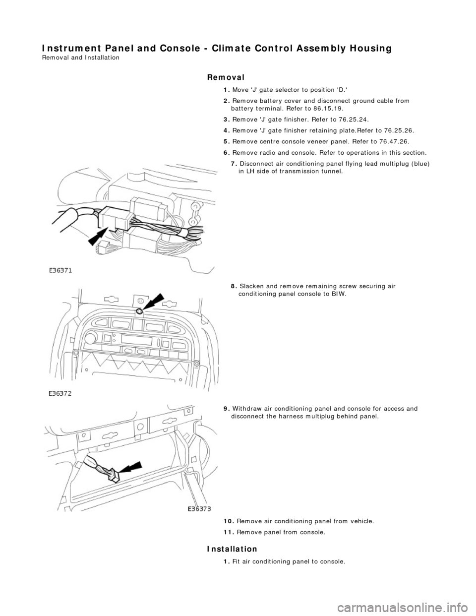
Instrument Panel and Console - Climate Control Assembly Housing
Removal and Installation
Removal
Installation
1. Move 'J' gate selector to position 'D.'
2. Remove battery cover and disc onnect ground cable from
battery terminal. Refer to 86.15.19.
3. Remove 'J' gate finish er. Refer to 76.25.24.
4. Remove 'J' gate finisher reta ining plate.Refer to 76.25.26.
5. Remove centre console veneer panel. Refer to 76.47.26.
6. Remove radio and console. Refer to operations in this section.
7. Disconnect air conditioning panel flying lead multiplug (blue)
in LH side of transmission tunnel.
8. Slacken and remove remaining screw securing air
conditioning panel console to BIW.
9. Withdraw air conditioning panel and console for access and
disconnect the harness multiplug behind panel.
10. Remove air conditioning panel from vehicle.
11. Remove panel from console.
1. Fit air conditioning panel to console.
Page 2275 of 2490
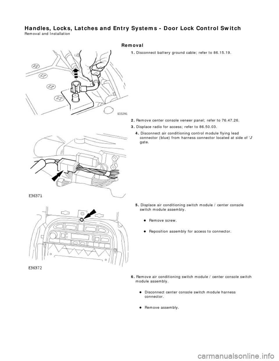
Handles, Locks, Latches and Entry Systems - Door Lock Control Switch
Removal and Installation
Removal
1. Disconnect battery ground cable; refer to 86.15.19.
2. Remove center console veneer panel; refer to 76.47.26.
3. Displace radio for access; refer to 86.50.03.
4. Disconnect air conditioning control module flying lead
connector (blue) from harness connector located at side of 'J'
gate.
5. Displace air conditioning switch module / center console
switch module assembly.
Remove screw.
Reposition assembly for access to connector.
6. Remove air conditioning switch module / center console switch
module assembly.
Disconnect center console switch module harness
connector.
Remove assembly.
Page 2409 of 2490
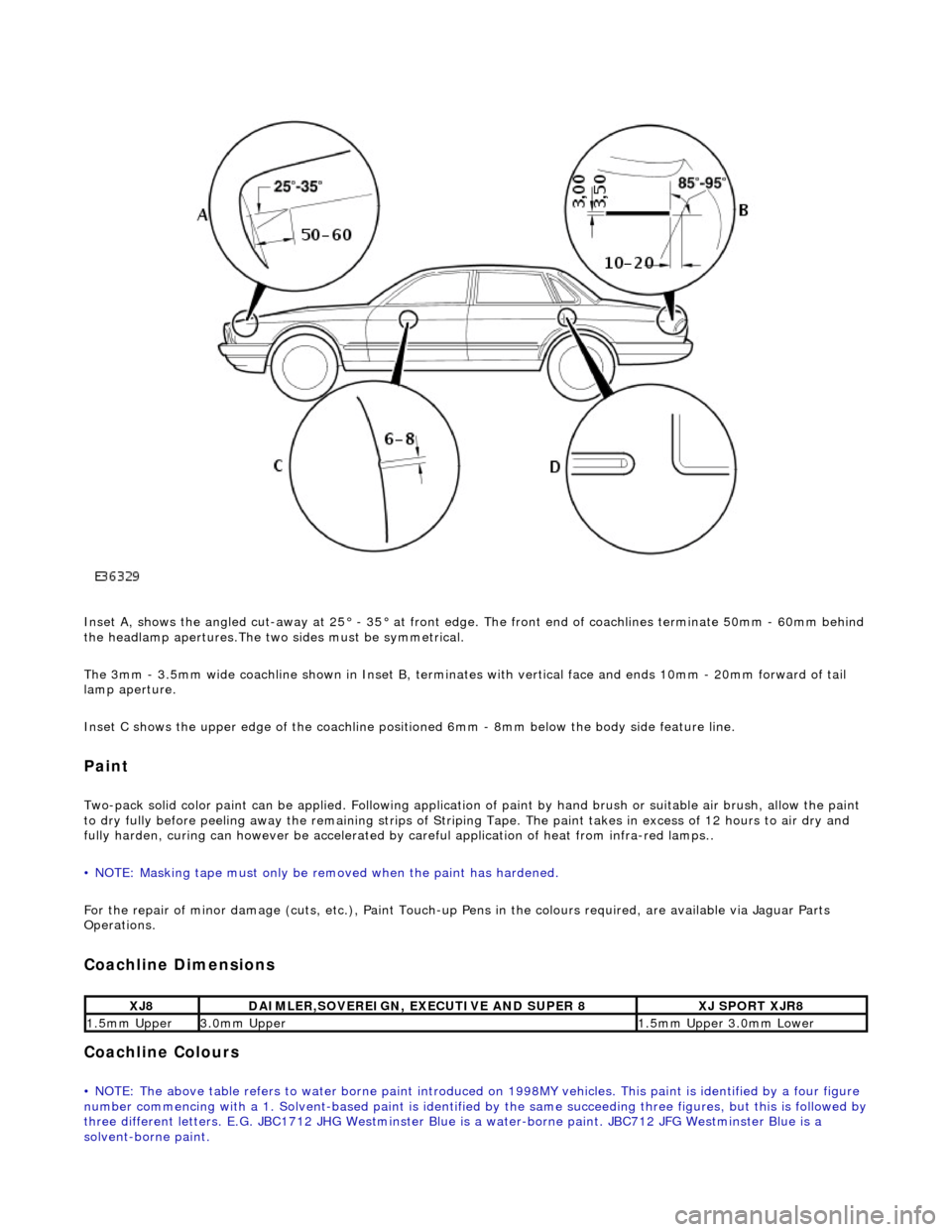
Inset A, shows the angled cut-away at 25° - 35° at front edge. The front end of coachlines terminate 50mm - 60mm behind
the headlamp apertures.The two sides must be symmetrical.
The 3mm - 3.5mm wide coachline shown in Inset B, terminates with vertical face and ends 10mm - 20mm forward of tail
lamp aperture.
Inset C shows the upper edge of th e coachline positioned 6mm - 8mm be low the body side feature line.
Paint
Two-pack solid color paint can be applied. Following application of paint by hand brus h or suitable air brush, allow the paint
to dry fully before peeling away the remain ing strips of Striping Tape. The paint takes in excess of 12 hours to air dry and
fully harden, curing can however be accelerated by careful application of heat from infra-red lamps..
• NOTE: Masking tape must only be removed when the paint has hardened.
For the repair of minor damage (cuts, et c.), Paint Touch-up Pens in the colours required, are available via Jaguar Parts
Operations.
Coachline Dimensions
Coachline Colours
• NOTE: The above table refers to water borne paint introduced on 1998MY vehicles. This paint is identified by a four figure
number commencing with a 1. Solvent-based paint is identified by the same succeeding three figures, but this is followed by three different letters. E.G. JBC1712 JHG Westminster Blue is a water-borne paint. JBC712 JFG Westminster Blue is a
solvent-borne paint.
XJ8DAIMLER,SOVEREIGN, EXECUTIVE AND SUPER 8XJ SPORT XJR8
1.5mm Upper3.0mm Upper1.5mm Upper 3.0mm Lower
Page 2410 of 2490
GLAZING
In order that the design condition of the vehicle is preserved when direct glazing repairs are carried out, it is essential that
only approved materials an d processes are employed.
Glass and Body Preparation
Betaseal HV3 System methods an d materials, are used on all Jaguar vehicles . Ease of working and extended process time
can however be gained by ensuring that the vehicle body and replacement glass are at a minimum room temperature of 20°
C prior to adhesive a pplication and fitting.
In the event of damage to the body flange finish, rectify as appropriate with the full paint refinishing process as described in
the Paint Refinishing Manual.
Adhesive Application Temperature
The specified adhesive has a high viscosity and is not easily applied at 'room te mperature' using conventional methods.
When the adhesive is applied it chills ra pidly on contact with the body and reverts to the hard condition, providing retention
strength with in minutes.
Raising the temperature of the adhesive will reduce viscosity an d speed up the flow. It is recommended that the adhesive is
pre-warmed in a heated cabinet for a mini mum of twenty minutes and applied with an extrusion gun incorporating integral
heating elements.
Adhesive Application
CAUTION: The glass will not bond to the body if the time taken to apply the adhesive and position the glass, exceeds
the stated limit.
It is recommended that the be ad of adhesive conforms to the shape and dimensions shown in the Adhesive Application
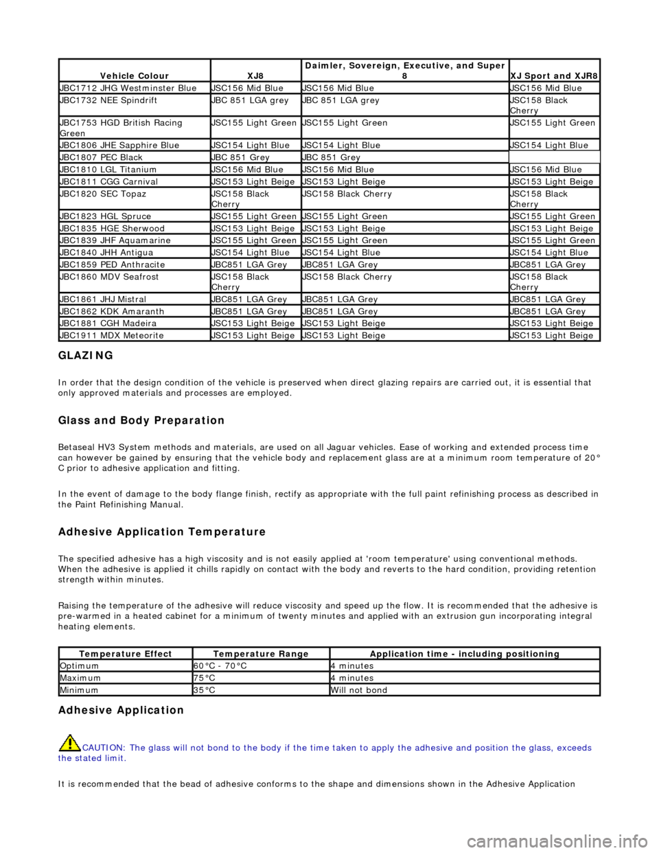
Vehicle ColourXJ8Daimler, Sovereign, Executive, and Super
8XJ Sport and XJR8
JBC1712 JHG Westminster BlueJSC156 Mid BlueJSC156 Mid BlueJSC156 Mid Blue
JBC1732 NEE SpindriftJBC 851 LGA greyJBC 851 LGA greyJSC158 Black
Cherry
JBC1753 HGD British Racing
GreenJSC155 Light GreenJSC155 Light GreenJSC155 Light Green
JBC1806 JHE Sapphire BlueJSC154 Light BlueJSC154 Light BlueJSC154 Light Blue
JBC1807 PEC BlackJBC 851 GreyJBC 851 Grey
JBC1810 LGL TitaniumJSC156 Mid BlueJSC156 Mid BlueJSC156 Mid Blue
JBC1811 CGG CarnivalJSC153 Light BeigeJSC153 Light BeigeJSC153 Light Beige
JBC1820 SEC TopazJSC158 Black
CherryJSC158 Black CherryJSC158 Black
Cherry
JBC1823 HGL SpruceJSC155 Light GreenJSC155 Light GreenJSC155 Light Green
JBC1835 HGE SherwoodJSC153 Light BeigeJSC153 Light BeigeJSC153 Light Beige
JBC1839 JHF AquamarineJSC155 Light GreenJSC155 Light GreenJSC155 Light Green
JBC1840 JHH AntiguaJSC154 Light BlueJSC154 Light BlueJSC154 Light Blue
JBC1859 PED AnthraciteJBC851 LGA GreyJBC851 LGA GreyJBC851 LGA Grey
JBC1860 MDV SeafrostJSC158 Black
CherryJSC158 Black CherryJSC158 Black
Cherry
JBC1861 JHJ MistralJBC851 LGA GreyJBC851 LGA GreyJBC851 LGA Grey
JBC1862 KDK AmaranthJBC851 LGA GreyJBC851 LGA GreyJBC851 LGA Grey
JBC1881 CGH MadeiraJSC153 Light BeigeJSC153 Light BeigeJSC153 Light Beige
JBC1911 MDX MeteoriteJSC153 Light BeigeJSC153 Light BeigeJSC153 Light Beige
Temperature EffectTemperature RangeApplication time - including positioning
Optimum60°C - 70°C4 minutes
Maximum75°C4 minutes
Minimum35°CWill not bond