Page 278 of 2490

Vehicle Dynamic Suspension - Vehicle Dynamic Suspension
Diagn
osis and Testing
Refer to the PDU User Guide for details of diagnosing and testing the Adaptive Damping System. The PDU interrogates the
ADCM directly via the K and L lines to the J1962 diagnostic socket.
The PDU will give an indication of the integrity of each electron ic and electrical component. It will indicate, for example, that
the accelerometers are not broken, but not that they functionin g correctly when the vehicle is in motion. However, it is
exceptional for an accelero meter to function incorrectly in its dynamic mode if it is proved to be functioning when static.
Basic Checks
The accele
rometers have the following ch
aracteristics. At 0g (no movement of the body) each vertical accelerometer
outputs approximately 2.5V steady voltage; the lateral acce lerometer outputs approximately 1.5V. The voltage output due
to body movement is proportional to acceleration in the acceleration axis, up to approximately 4.5V and down to
approximately 0.5V.
Before changing any component, refer to the circuit diagrams and check the cont inuity of relevant harness circuits; in some
instances, the PDU will not different iate between a faulty component an d a damaged connection or wiring.
Check the following fuses:
En
gine compartment fuse
box, fuse F5 (10A).
Engine m
anagement fuse
box, fuse F1 (20A).
Check the following ADCM input/output lines:
Sy stem erro
r output from the ADCM
to the instrument cluster.
Vehicl
e speed output from the inst
rument cluster to the ADCM.
Foo
tbrake signal to the ADCM.
Check any relevant connections to confirm that the connection is electrically sound and that a terminal pin has not been
pushed back into the connector shell, ie. not ma king a connection to its mating pin or socket.
Page 1975 of 2490

Location of J1962 socket
The J1962 socket is located at the driver side inboard footwell.
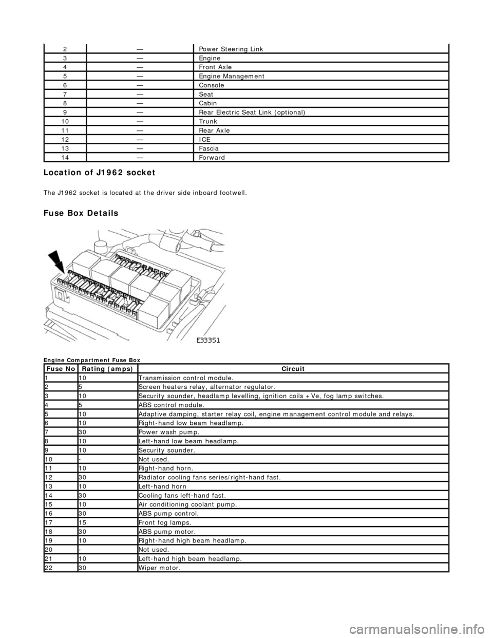
Fuse Box Details
Engine Compartment Fuse Box
2—Power Steering Link
3—Engine
4—Front Axle
5—Engine Management
6—Console
7—Seat
8—Cabin
9—Rear Electric Seat Link (optional)
10—Trunk
11—Rear Axle
12—ICE
13—Fascia
14—Forward
Fuse NoRating (amps)Circuit
110Transmission control module.
25Screen heaters relay, alternator regulator.
310Security sounder, headlamp levelling, ignition coils +Ve, fog lamp switches.
45ABS control module.
510Adaptive damping, starter relay coil, engine management control module and relays.
610Right-hand low beam headlamp.
730Power wash pump.
810Left-hand low beam headlamp.
910Security sounder.
10-Not used.
1110Right-hand horn.
1230Radiator cooling fans series/right-hand fast.
1310Left-hand horn
1430Cooling fans left-hand fast.
1510Air conditioning coolant pump.
1630ABS pump control.
1715Front fog lamps.
1830ABS pump motor.
1910Right-hand high beam headlamp.
20-Not used.
2110Left-hand high beam headlamp.
2230Wiper motor.
Page 1976 of 2490

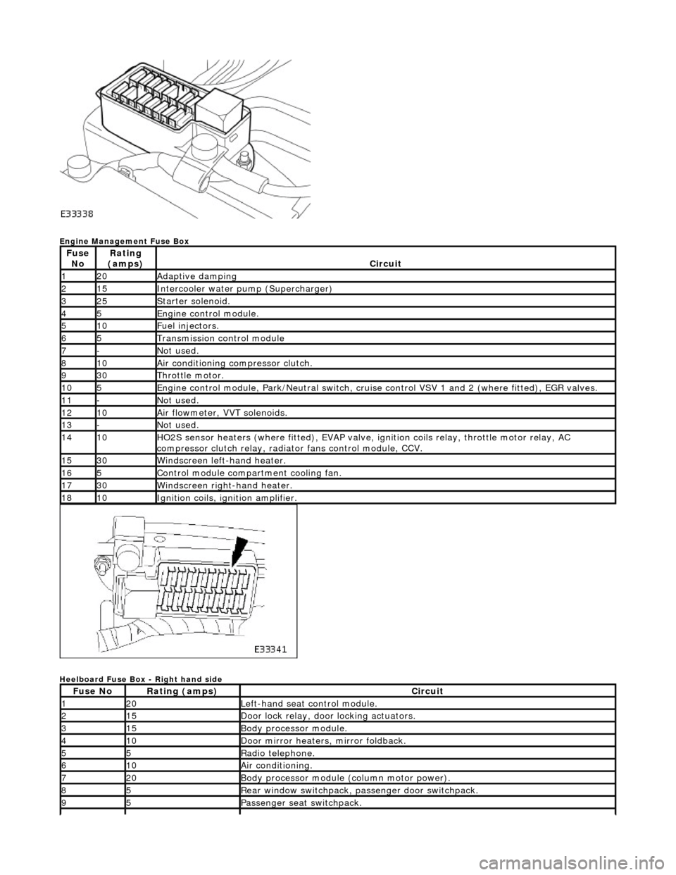
Engine Management Fuse Box
Heelboard Fuse Box - Right hand side
Fuse NoRating
(amps)Circuit
120Adaptive damping
215Intercooler water pump (Supercharger)
325Starter solenoid.
45Engine control module.
510Fuel injectors.
65Transmission control module
7-Not used.
810Air conditioning compressor clutch.
930Throttle motor.
105Engine control module, Park/Neutr al switch, cruise control VSV 1 and 2 (where fitted), EGR valves.
11-Not used.
1210Air flowmeter, VVT solenoids.
13-Not used.
1410HO2S sensor heaters (where fitted ), EVAP valve, ignition coils relay, throttle motor relay, AC
compressor clutch relay, radi ator fans control module, CCV.
1530Windscreen left-hand heater.
165Control module compartment cooling fan.
1730Windscreen right-hand heater.
1810Ignition coils, ignition amplifier.
Fuse NoRating (amps)Circuit
120Left-hand seat control module.
215Door lock relay, door locking actuators.
315Body processor module.
410Door mirror heaters, mirror foldback.
55Radio telephone.
610Air conditioning.
720Body processor module (column motor power).
85Rear window switchpack, passenger door switchpack.
95Passenger seat switchpack.