Page 505 of 2490
Steering Column - Steering Column
Description an
d Operation
Stee
ring Wheel
T
he steering wheel assembly incorporates:
The s
peed control switchpack.
The i
n-car entertainment (ICE) switchpack.
The h
orn pad.
The driver ai
r bag module; refer to Section
501
-20A Safety Belt
System
Sectio
n
501
-2
0B Supplemental Restraint
Sy
stem
.
I
CE Switchpack
The
in-car entertainment (ICE) switchpack is installed to the le
ft of the steering wheel center, controlling the ICE functions
and telephone (where fitted). The switchpack overrides the corresponding bu ttons on the ICE control panel and performs
the following functions:
1. 1. Increase the volume of the select ed audio output or telephone.
It
em
Par
t Number
De
scription
1-Spe
ed control switchpack
2-I
CE switchpack
3-Horn pad
4-Air bag lo
cation
It
em
Par
t Number
De
scription
1-Vol
ume increase
2-ICE func
tions/teleph
one mode select
3-Volum
e decrease
4-ICE pres
ets/telephone memory select
Page 506 of 2490

2.2. Press and rel e
ase to cycle through radio FM, radio AM,
tape cassette, or CD player. Press and hold for two
seconds to select telephone mode.
3. 3. Decrease the volume of the select ed audio output or telephone.
4. 4. Press and release to select the next pr eset radio station, or the next track on tape or CD. Press and hold for two
seconds to select the next radio station on the waveband upwards, or the next CD loaded in the player, or to
change the side of tape. When in te lephone mode, press and release to scroll up to the next memory location.
Press and hold for two seconds to send and end a call.
Speed Control Switchpa ck
The s p
eed control switchpack is installed to the right of th
e steering wheel center and performs the following functions:
1. 1. Set the desired speed or increase the set speed.
2. 2. Resume the previously set speed.
3. 3. Decrease the set speed.
4. 4. Cancel speed control without erasing the set speed.
Horn and Driver Airbag Location
Ite
m
Par
t
Number
De
scr
iption
1-Se
t
speed or increase speed
2-Re
sum
e
3-De
creas
e speed
4-Cancel
Ite
m
Part
Number
Descr
iption
1-Horn operatin
g pad
The ho
rn operating pad is mounted in the central area of the steering wheel.
2-Driver air bag location
Page 1885 of 2490

If the field were not controlled, the 'B+' output would rise to a level which could damage bulbs and ECMs. The regulator
compares the output voltage to an intern al voltage reference circuit to achieve the controlled output of the generator.
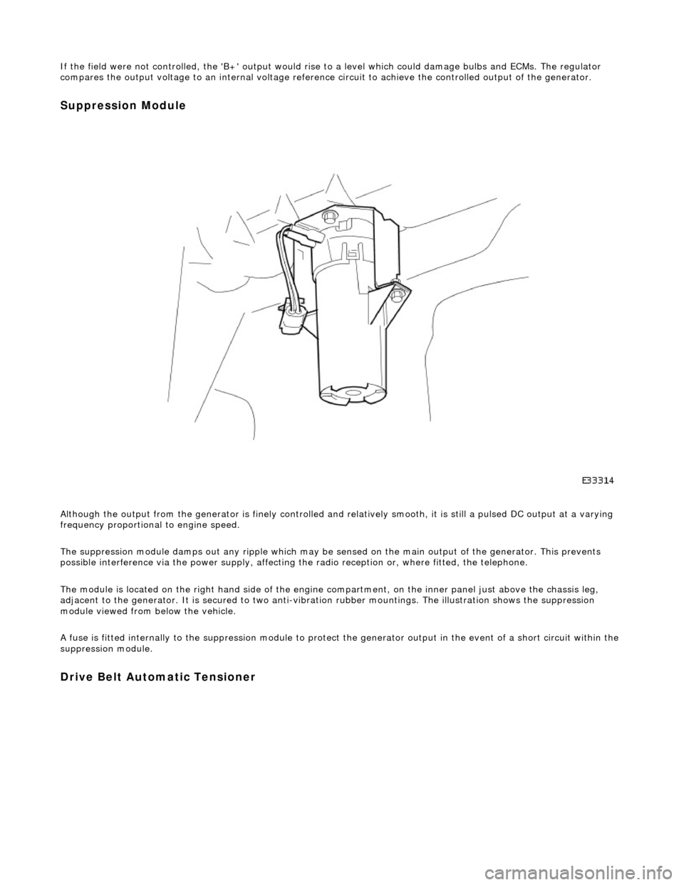
Suppression Module
Although the output from the generator is fi nely controlled and relatively smooth, it is still a pulsed DC output at a varying
frequency proportional to engine speed.
The suppression module damps ou t any ripple which may be sensed on the main output of the generator. This prevents
possible interference via the power supply, affecting the radio reception or, where fitted, the telephone.
The module is located on the right hand side of the engine compartment, on the inner panel just above the chassis leg,
adjacent to the generator. It is secured to two anti-vibration rubber moun tings. The illustration shows the suppression
module viewed from below the vehicle.
A fuse is fitted internally to the suppression module to protect the generator output in the event of a short circuit within th e
suppression module.
Drive Belt Automatic Tensioner
Page 1904 of 2490
Audio Unit - Audio System
Description and Operation
The choice of two entertainment system s is available; base or premium.
The base system comprises a radio cassette player with in tegral message display and "Phone Ready" controls for an
accessory telephone; door speakers and tweeters.
The premium system has the following additional components: power amplifier, CD autochanger, sub-woofer and 'A' post
tweeters fitted instead of front door tweeters.
Both systems can be operated remotely by use of switches loca ted on the steering wheel and have an electrically operated
aerial.
Telephone controls incorporated in the ra dio cassette unit facilitate inclusion of the GSM hands free telephone system
available as optional equipment.
After diagnostic or repair operations, refer to the Sound System Handbook for setting-up procedures and operation.
Page 1976 of 2490

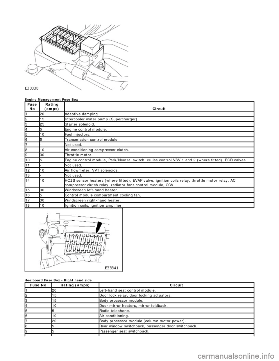
Engine Management Fuse Box
Heelboard Fuse Box - Right hand side
Fuse NoRating
(amps)Circuit
120Adaptive damping
215Intercooler water pump (Supercharger)
325Starter solenoid.
45Engine control module.
510Fuel injectors.
65Transmission control module
7-Not used.
810Air conditioning compressor clutch.
930Throttle motor.
105Engine control module, Park/Neutr al switch, cruise control VSV 1 and 2 (where fitted), EGR valves.
11-Not used.
1210Air flowmeter, VVT solenoids.
13-Not used.
1410HO2S sensor heaters (where fitted ), EVAP valve, ignition coils relay, throttle motor relay, AC
compressor clutch relay, radi ator fans control module, CCV.
1530Windscreen left-hand heater.
165Control module compartment cooling fan.
1730Windscreen right-hand heater.
1810Ignition coils, ignition amplifier.
Fuse NoRating (amps)Circuit
120Left-hand seat control module.
215Door lock relay, door locking actuators.
315Body processor module.
410Door mirror heaters, mirror foldback.
55Radio telephone.
610Air conditioning.
720Body processor module (column motor power).
85Rear window switchpack, passenger door switchpack.
95Passenger seat switchpack.
Page 1977 of 2490

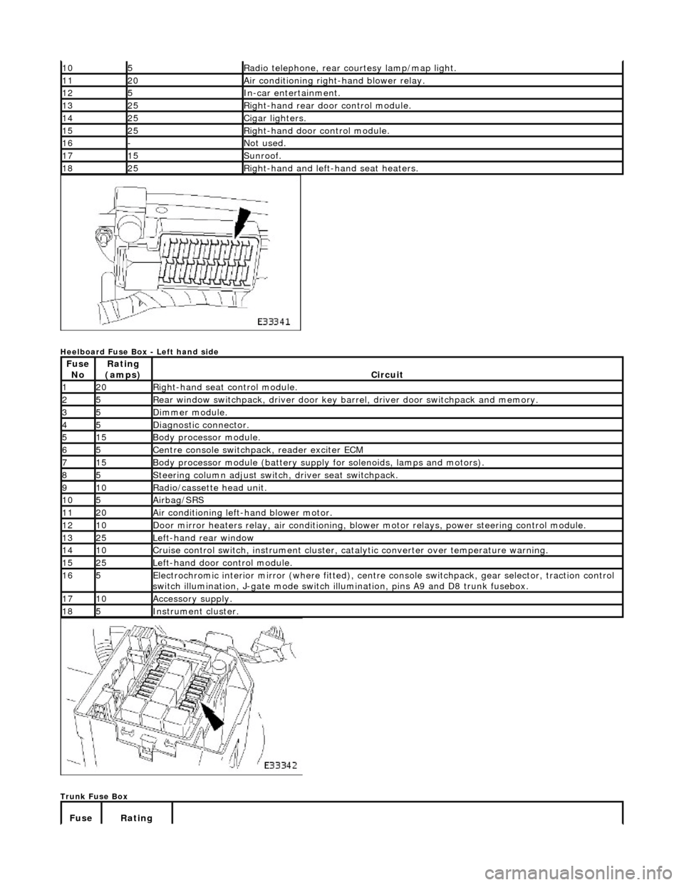
Heelboard Fuse Box - Left hand side
Trunk Fuse Box
105Radio telephone, rear courtesy lamp/map light.
1120Air conditioning right-hand blower relay.
125In-car entertainment.
1325Right-hand rear door control module.
1425Cigar lighters.
1525Right-hand door control module.
16-Not used.
1715Sunroof.
1825Right-hand and left-hand seat heaters.
Fuse NoRating
(amps)Circuit
120Right-hand seat control module.
25Rear window switchpack, driver door key ba rrel, driver door switchpack and memory.
35Dimmer module.
45Diagnostic connector.
515Body processor module.
65Centre console switchpack, reader exciter ECM
715Body processor module (battery supply for solenoids, lamps and motors).
85Steering column adjust switch, driver seat switchpack.
910Radio/cassette head unit.
105Airbag/SRS
1120Air conditioning left-hand blower motor.
1210Door mirror heaters relay, air conditioning, blow er motor relays, power steering control module.
1325Left-hand rear window
1410Cruise control switch, instrument cluster, catalytic converter over temperature warning.
1525Left-hand door control module.
165Electrochromic interior mirror (where fitted), centre console switchpack, gear selector, traction control
switch illumination, J-gate mode switch illumination, pins A9 and D8 trunk fusebox.
1710Accessory supply.
185Instrument cluster.
Fuse Rating
Page 1996 of 2490

Items can be ordered from:
SPX United Kingdom Limited
Ironstone Way
Brixworth
Northants
NN6 9UD
United Kingdom
Telephone: +44 (0) 1327 704461
Fax: +44 (0) 1327 706632
Repair Methods
CAUTION: Several different types and sizes of terminal may be found in a single electrical connector
housing.
It is necessary to identify:
The conductor (wire) size of the affected wiring harness The electrical connector range from which the damaged wiring harness is to be removed The terminal type
Use of the approved diagnostic tool will greatly assist in th e quick identification of electrical connectors and faulty pin
terminal(s).
Reference can also be made to the vehicle Electrical Guides, he ld by Dealers, to identify wiring harness(s) and electrical
connector(s).
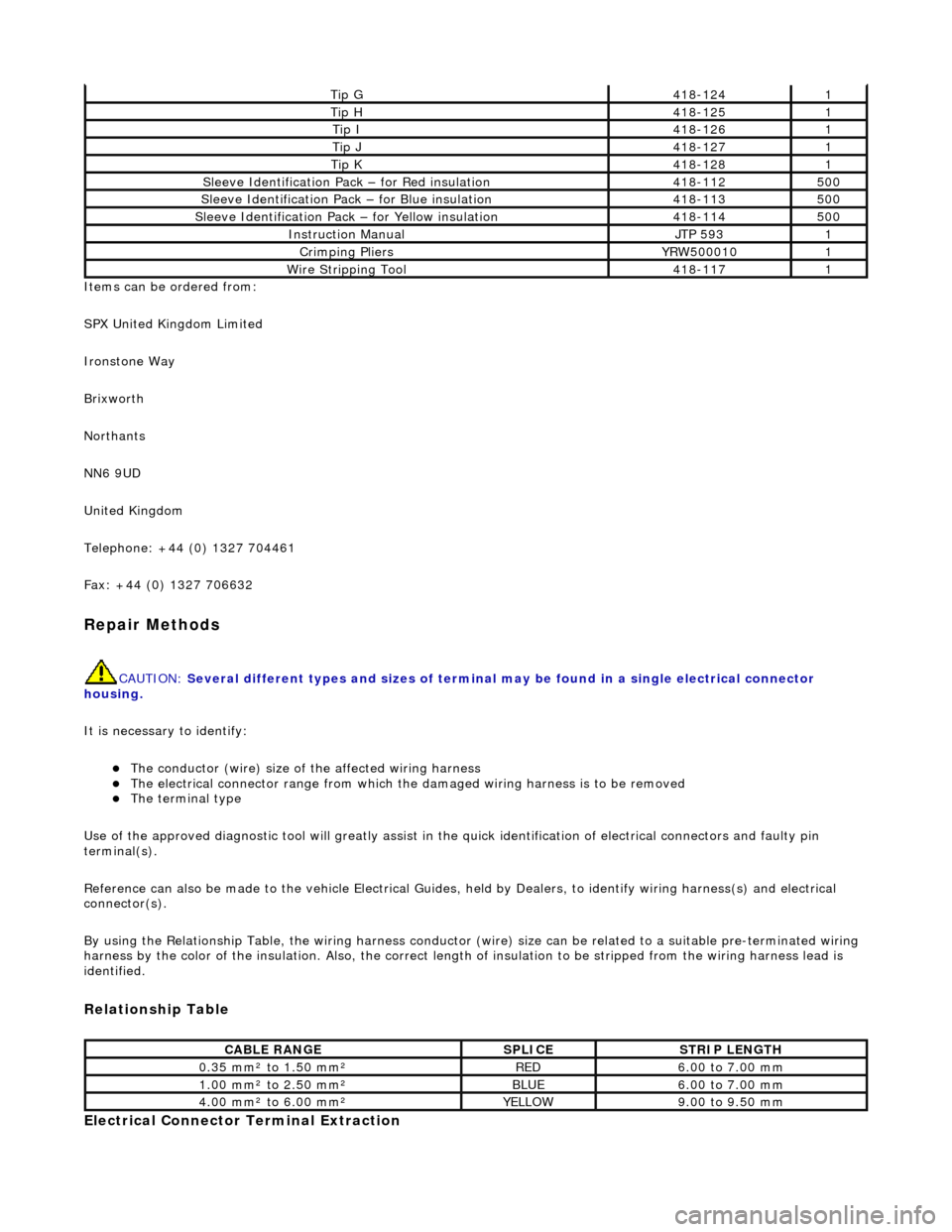
By using the Relationship Table, the wiring harness conductor (wire) size can be related to a suitable pre-terminated wiring
harness by the color of the insulation. Also , the correct length of insulation to be stripped from the wiring harness lead is
identified.
Relationship Table
Electrical Connector Terminal Extraction
Tip G418-1241
Tip H418-1251
Tip I418-1261
Tip J418-1271
Tip K418-1281
Sleeve Identification Pa ck – for Red insulation418-112500
Sleeve Identification Pack – for Blue insulation 418-113500
Sleeve Identification Pack – for Yellow insulation 418-114500
Instruction Manual JTP 5931
Crimping Pliers YRW5000101
Wire Stripping Tool 418-1171
CABLE RANGE SPLICE STRIP LENGTH
0.35 mm² to 1.50 mm²RED6.00 to 7.00 mm
1.00 mm² to 2.50 mm²BLUE6.00 to 7.00 mm
4.00 mm² to 6.00 mm²YELLOW9.00 to 9.50 mm
Page 2267 of 2490
Instrument Panel and Console - Overhead Console
Removal and Installation
Removal
1. Remove battery cover and disconnect ground cable from
battery terminal. Refer to 86.15.19.
2. Open roof console sun glasses compartment.
3. Rotate fastener 1/4 turn to release console.
4. Lower console from roof and disconnect lighting module
harness multiplug and hands- free microphone harness
multiplug if telephone is fitted.
5. Release roof console from retaining clips and remove from
vehicle.