Page 1560 of 3573
6A Ð 10 ENGINE MECHANICAL
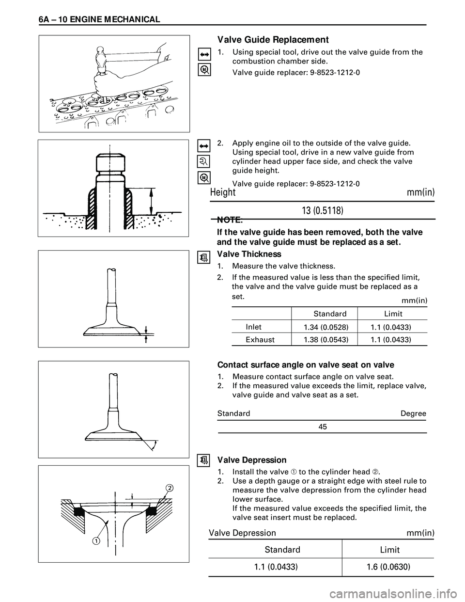
Valve Guide Replacement
1. Using special tool, drive out the valve guide from the
combustion chamber side.
Valve guide replacer: 9-8523-1212-0
2. Apply engine oil to the outside of the valve guide.
Using special tool, drive in a new valve guide from
cylinder head upper face side, and check the valve
guide height.
Valve guide replacer: 9-8523-1212-0
NOTE:
If the valve guide has been removed, both the valve
and the valve guide must be replaced as a set.
Valve Thickness
1. Measure the valve thickness.
2. If the measured value is less than the specified limit,
the valve and the valve guide must be replaced as a
set.
Contact surface angle on valve seat on valve
1. Measure contact surface angle on valve seat.
2. If the measured value exceeds the limit, replace valve,
valve guide and valve seat as a set.
mm(in)
13 (0.5118) Height
Standard
mm(in)
Limit
1.1 (0.0433)
1.6 (0.0630)
Valve Depression
Degree
45 Standard
Valve Depression
1. Install the valve À to the cylinder head Á.
2. Use a depth gauge or a straight edge with steel rule to
measure the valve depression from the cylinder head
lower surface.
If the measured value exceeds the specified limit, the
valve seat insert must be replaced.
Inletmm(in)1.1 (0.0433) Standard Limit
Exhaust1.34 (0.0528)
1.1 (0.0433) 1.38 (0.0543)
Page 1561 of 3573

ENGINE MECHANICAL 6A Ð 11
Valve Contact Width
1. Check the valve contact faces for roughness and
unevenness. Make smooth the valve contact sur-
faces.
2. Measure the valve contact width.
If the measured value exceeds the specified limit, the
valve seat insert must be replaced.
Valve Seat Insert Replacement
Valve Seat Insert Removal
1. Arc weld the entire inside circumference À of the
valve seat insert Á.
2. Allow the valve seat insert to cool for a few minutes.
This will invite contraction and make removal of the
valve seat insert easier.
3. Use a screwdriver  to pry the valve seat insert free.
Take care not to damage the cylinder head Ö .
4. Carefully remove carbon and other foreign material
from the cylinder head insert bore.
Valve Seat Insert Installation
1. Carefully place the attachment À (having a smaller
outside diameter than the valve seat insert) on the
valve seat insert Á .
Note:
The smooth side of the attachment must contact
the valve seat insert.
2. Use a bench press  to gradually apply pressure to
the attachment and press the valve seat insert into
place.
Note:
Do not apply an excessive amount of pressure with
the bench press. Damage to the valve seat insert
will result.
Valve Seat Insert Correction
1. Remove the carbon from the valve seat insert surface.
2. Use a valve cutter (15°, 45°, and 75° blades) to mini-
mize scratches and other rough areas. this will bring
the contact width back to the standard value.
Remove only the scratches and rough areas. Do not
cut away too much. Take care not to cut away un-
blemished areas of the valve seat surface.
Inlet
mm(in)
2.2 (0.0866)
Standard Limit
Exhaust1.7 (0.0669)
2.5 (0.0984) 2.0 (0.0787)
Page 1564 of 3573
6A Ð 14 ENGINE MECHANICAL
CAMSHAFT, TAPPET
6. Camshaft Timing Gear
·Install the stopper bolt 1 to the timing pulley to
prevent it from turning.
·Use the timing pulley puller 2 to remove the
pulley.
Camshaft Timing Pulley Puller: 5-8840-0086-0
7. Camshaft Thrust Plate
DISASSEMBLY
1. Cylinder Head Assembly
2. Flywheel
3. Cylinder Block rear Plate
4. Crankcase Assembly
5. Oil Pump Assembly
Page 1566 of 3573
6A Ð 16 ENGINE MECHANICAL
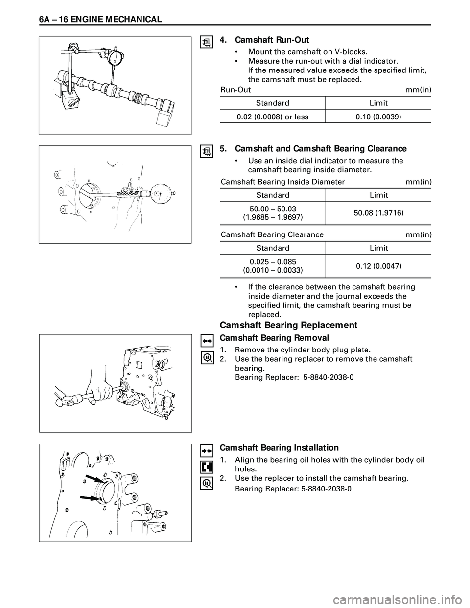
4. Camshaft Run-Out
¥ Mount the camshaft on V-blocks.
¥ Measure the run-out with a dial indicator.
If the measured value exceeds the specified limit,
the camshaft must be replaced.
5. Camshaft and Camshaft Bearing Clearance
¥ Use an inside dial indicator to measure the
camshaft bearing inside diameter.
Standard Limit
mm(in)
0.02 (0.0008) or less 0.10 (0.0039) Run-Out
¥ If the clearance between the camshaft bearing
inside diameter and the journal exceeds the
specified limit, the camshaft bearing must be
replaced.
Camshaft Bearing Replacement
Camshaft Bearing Removal
1. Remove the cylinder body plug plate.
2. Use the bearing replacer to remove the camshaft
bearing.
Bearing Replacer: 5-8840-2038-0
Camshaft Bearing Installation
1. Align the bearing oil holes with the cylinder body oil
holes.
2. Use the replacer to install the camshaft bearing.
Bearing Replacer: 5-8840-2038-0
Standard Limit
mm(in)
50.00 – 50.03
(1.9685 – 1.9697)50.08 (1.9716) Camshaft Bearing Inside Diameter
Standard Limit
mm(in)
0.025 – 0.085
(0.0010 – 0.0033)0.12 (0.0047) Camshaft Bearing Clearance
Page 1576 of 3573
6A Ð 26 ENGINE MECHANICAL
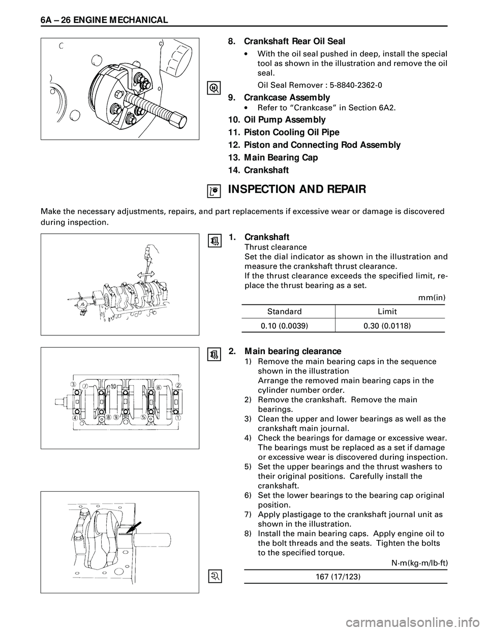
8. Crankshaft Rear Oil Seal
·With the oil seal pushed in deep, install the special
tool as shown in the illustration and remove the oil
seal.
Oil Seal Remover : 5-8840-2362-0
9. Crankcase Assembly
·Refer to ÒCrankcaseÓ in Section 6A2.
10. Oil Pump Assembly
11. Piston Cooling Oil Pipe
12. Piston and Connecting Rod Assembly
13. Main Bearing Cap
14. Crankshaft
INSPECTION AND REPAIR
Make the necessary adjustments, repairs, and part replacements if excessive wear or damage is discovered
during inspection.
1. Crankshaft
Thrust clearance
Set the dial indicator as shown in the illustration and
measure the crankshaft thrust clearance.
If the thrust clearance exceeds the specified limit, re-
place the thrust bearing as a set.
Standard Limit
mm(in)
0.10 (0.0039) 0.30 (0.0118)
167 (17/123)N·m(kg·m/lb·ft)
2. Main bearing clearance
1) Remove the main bearing caps in the sequence
shown in the illustration
Arrange the removed main bearing caps in the
cylinder number order.
2) Remove the crankshaft. Remove the main
bearings.
3) Clean the upper and lower bearings as well as the
crankshaft main journal.
4) Check the bearings for damage or excessive wear.
The bearings must be replaced as a set if damage
or excessive wear is discovered during inspection.
5) Set the upper bearings and the thrust washers to
their original positions. Carefully install the
crankshaft.
6) Set the lower bearings to the bearing cap original
position.
7) Apply plastigage to the crankshaft journal unit as
shown in the illustration.
8) Install the main bearing caps. Apply engine oil to
the bolt threads and the seats. Tighten the bolts
to the specified torque.
Page 1577 of 3573
ENGINE MECHANICAL 6A Ð 27
NOTE:
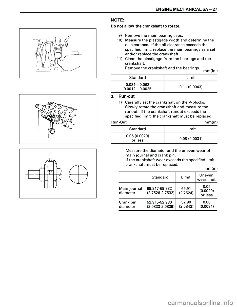
Do not allow the crankshaft to rotate.
9) Remove the main bearing caps.
10) Measure the plastigage width and determine the
oil clearance. If the oil clearance exceeds the
specified limit, replace the main bearings as a set
and/or replace the crankshaft.
11) Clean the plastigage from the bearings and the
crankshaft.
Remove the crankshaft and the bearings.
3. Run-out
1) Carefully set the crankshaft on the V-blocks.
Slowly rotate the crankshaft and measure the
runout. If the crankshaft runout exceeds the
specified limit, the crankshaft must be replaced.
Measure the diameter and the uneven wear of
main journal and crank pin.
If the crankshaft wear exceeds the specified limit,
crankshaft must be replaced.
Standard Limit
mm(in.)
0.031 – 0.063
(0.0012 – 0.0025)0.11 (0.0043)
Standard Limit
mm(in)
0.05 (0.0020)
or less0.08 (0.0031) Run-Out
Standard Limitmm(in)
Main journal
diameter69.91
(2.7524)
69.917-69.932
(2.7526-2.7532)
Crank pin
diameter52.90
(2.0843) 52.915-52.930
(2.0833-2.0839)
Uneven
wear limit
0.05
(0.0020)
or less
0.08
(0.0031)
Page 1582 of 3573
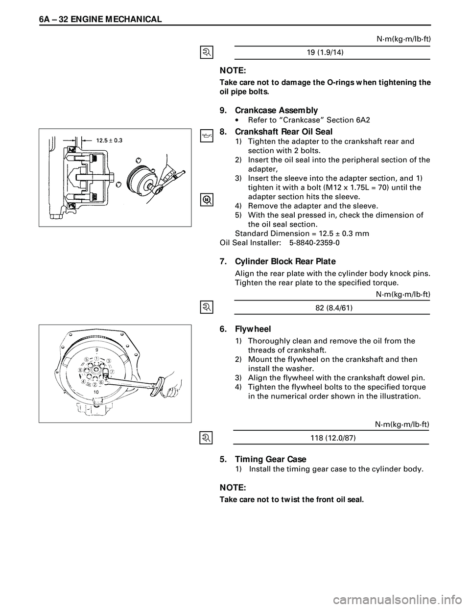
6A Ð 32 ENGINE MECHANICAL
19 (1.9/14)N·m(kg·m/lb·ft)
5. Timing Gear Case
1) Install the timing gear case to the cylinder body.
NOTE:
Take care not to twist the front oil seal.
6. Flywheel
1) Thoroughly clean and remove the oil from the
threads of crankshaft.
2) Mount the flywheel on the crankshaft and then
install the washer.
3) Align the flywheel with the crankshaft dowel pin.
4) Tighten the flywheel bolts to the specified torque
in the numerical order shown in the illustration.
82 (8.4/61)N·m(kg·m/lb·ft)
NOTE:
Take care not to damage the O-rings when tightening the
oil pipe bolts.
9. Crankcase Assembly
·Refer to ÒCrankcaseÓ Section 6A2
8. Crankshaft Rear Oil Seal
1) Tighten the adapter to the crankshaft rear and
section with 2 bolts.
2) Insert the oil seal into the peripheral section of the
adapter,
3) Insert the sleeve into the adapter section, and 1)
tighten it with a bolt (M12 x 1.75L = 70) until the
adapter section hits the sleeve.
4) Remove the adapter and the sleeve.
5) With the seal pressed in, check the dimension of
the oil seal section.
Standard Dimension = 12.5 ± 0.3 mm
Oil Seal Installer: 5-8840-2359-0
7. Cylinder Block Rear Plate
Align the rear plate with the cylinder body knock pins.
Tighten the rear plate to the specified torque.
118 (12.0/87)N·m(kg·m/lb·ft)
Page 1584 of 3573
6A Ð 34 ENGINE MECHANICAL
PISTON AND CONNECTING ROD
DISASSEMBLY
1. Cylinder Head Assembly
·Refer to ÒCylinder headÓ in Section 6A2.
2. Crankcase Assembly
·Refer to ÒCrankcaseÓ in Section 6A2
3. Oil Pump Assembly
4. Connecting Rod Bearing Cap
5. Piston and Connecting Rod
·Remove carbon deposits from the upper portion
of the cylinder wall with a scraper before
removing the piston and connecting rod