1998 ISUZU TROOPER check engine
[x] Cancel search: check enginePage 29 of 3573

0BÐ2 MAINTENANCE AND LUBRICATION
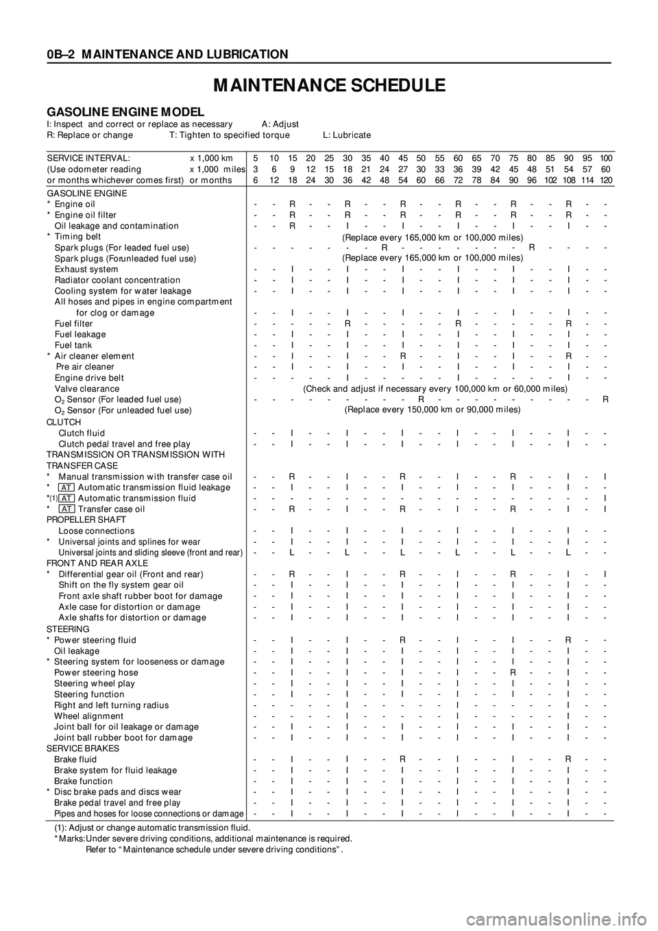
MAINTENANCE SCHEDULE
GASOLINE ENGINE MODELI: Inspect and correct or replace as necessary A: Adjust
R: Replace or change T: Tighten to specified torque L: Lubricate
SERVICE INTERVAL: x 1,000 km
(Use odometer reading x 1,000 miles
or months whichever comes first) or months5
3
610
6
1215
9
1820
12
2425
15
3030
18
3635
21
4240
24
4845
27
5450
30
6055
33
6660
36
7265
39
7870
42
8475
45
9080
48
9685
51
10290
54
10895
57
114100
60
120
GASOLINE ENGINE
* Engine oil
* Engine oil filter
Oil leakage and contamination
* Timing belt
Spark plugs (For leaded fuel use)
Spark plugs (For unleaded fuel use)
Exhaust system
Radiator coolant concentration
Cooling system for water leakage
All hoses and pipes in engine compartment
for clog or damage
Fuel filter
Fuel leakage
Fuel tank
* Air cleaner element
Pre air cleaner
Engine drive belt
Valve clearance
O
2 Sensor (For leaded fuel use)
O
2 Sensor (For unleaded fuel use)-
-
-
-
-
-
-
-
-
-
-
-
-
-
--
-
-
-
-
-
-
-
-
-
-
-
-
-
-R
R
R
-
I
I
I
I
-
I
I
I
I
-
--
-
-
-
-
-
-
-
-
-
-
-
-
-
--
-
-
-
-
-
-
-
-
-
-
-
-
-
-R
R
I
-
I
I
I
I
R
I
I
I
I
I
--
-
-
-
-
-
-
-
-
-
-
-
-
-
--
-
-
R
-
-
-
-
-
-
-
-
-
-
-R
R
I
-
I
I
I
I
-
I
I
R
I
-
--
-
-
-
-
-
-
-
-
-
-
-
-
-
R-
-
-
-
-
-
-
-
-
-
-
-
-
-
-R
R
I
-
I
I
I
I
R
I
I
I
I
I
--
-
-
-
-
-
-
-
-
-
-
-
-
-
--
-
-
-
-
-
-
-
-
-
-
-
-
-
-R
R
I
-
I
I
I
I
-
I
I
I
I
-
--
-
-
R
-
-
-
-
-
-
-
-
-
-
--
-
-
-
-
-
-
-
-
-
-
-
-
-
-R
R
I
-
I
I
I
I
R
I
I
R
I
I
--
-
-
-
-
-
-
-
-
-
-
-
-
-
--
-
-
-
-
-
-
-
-
-
-
-
-
-
R
(Replace every 165,000 km or 100,000 miles)
(Replace every 165,000 km or 100,000 miles)
(Check and adjust if necessary every 100,000 km or 60,000 miles)
(Replace every 150,000 km or 90,000 miles)
CLUTCH
Clutch fluid
Clutch pedal travel and free play
TRANSMISSION OR TRANSMISSION WITH
TRANSFER CASE
* Manual transmission with transfer case oil
* Automatic transmission fluid leakage
*
(1)Automatic transmission fluid
* Transfer case oil
PROPELLER SHAFT
Loose connections
*
Universal joints and splines for wear
Universal joints and sliding sleeve (front and rear)
FRONT AND REAR AXLE
* Differential gear oil (Front and rear)
Shift on the fly system gear oil
Front axle shaft rubber boot for damage
Axle case for distortion or damage
Axle shafts for distortion or damage-
-
-
-
-
-
-
-
-
-
-
-
-
--
-
-
-
-
-
-
-
-
-
-
-
-
-I
I
R
I
-
R
I
I
L
R
I
I
I
I-
-
-
-
-
-
-
-
-
-
-
-
-
--
-
-
-
-
-
-
-
-
-
-
-
-
-I
I
I
I
-
I
I
I
L
I
I
I
I
I-
-
-
-
-
-
-
-
-
-
-
-
-
--
-
-
-
-
-
-
-
-
-
-
-
-
-I
I
R
I
-
R
I
I
L
R
I
I
I
I-
-
-
-
-
-
-
-
-
-
-
-
-
--
-
-
-
-
-
-
-
-
-
-
-
-
-I
I
I
I
-
I
I
I
L
I
I
I
I
I-
-
-
-
-
-
-
-
-
-
-
-
-
--
-
-
-
-
-
-
-
-
-
-
-
-
-I
I
R
I
-
R
I
I
L
R
I
I
I
I-
-
-
-
-
-
-
-
-
-
-
-
-
--
-
-
-
-
-
-
-
-
-
-
-
-
-I
I
I
I
-
I
I
I
L
I
I
I
I
I-
-
-
-
-
-
-
-
-
-
-
-
-
--
-
I
-
I
I
-
-
-
I
-
-
-
-
ATATAT
STEERING
* Power steering fluid
Oil leakage
* Steering system for looseness or damage
Power steering hose
Steering wheel play
Steering function
Right and left turning radius
Wheel alignment
Joint ball for oil leakage or damage
Joint ball rubber boot for damage
SERVICE BRAKES
Brake fluid
Brake system for fluid leakage
Brake function
* Disc brake pads and discs wear
Brake pedal travel and free play
Pipes and hoses for loose connections or damage
-
-
-
-
-
-
-
-
-
-
-
-
-
-
-
--
-
-
-
-
-
-
-
-
-
-
-
-
-
-
-I
I
I
I
I
I
-
-
I
I
I
I
I
I
I
I-
-
-
-
-
-
-
-
-
-
-
-
-
-
-
--
-
-
-
-
-
-
-
-
-
-
-
-
-
-
-I
I
I
I
I
I
I
I
I
I
I
I
I
I
I
I-
-
-
-
-
-
-
-
-
-
-
-
-
-
-
--
-
-
-
-
-
-
-
-
-
-
-
-
-
-
-R
I
I
I
I
I
-
-
I
I
R
I
I
I
I
I-
-
-
-
-
-
-
-
-
-
-
-
-
-
-
--
-
-
-
-
-
-
-
-
-
-
-
-
-
-
-I
I
I
I
I
I
I
I
I
I
I
I
I
I
I
I-
-
-
-
-
-
-
-
-
-
-
-
-
-
-
--
-
-
-
-
-
-
-
-
-
-
-
-
-
-
-I
I
I
R
I
I
-
-
I
I
I
I
I
I
I
I-
-
-
-
-
-
-
-
-
-
-
-
-
-
-
--
-
-
-
-
-
-
-
-
-
-
-
-
-
-
-R
I
I
I
I
I
I
I
I
I
R
I
I
I
I
I-
-
-
-
-
-
-
-
-
-
-
-
-
-
-
--
-
-
-
-
-
-
-
-
-
-
-
-
-
-
-
(1): Adjust or change automatic transmission fluid.
*Marks: Under severe driving conditions, additional maintenance is required.
Refer to “Maintenance schedule under severe driving conditions”.
Page 42 of 3573

SERVICE INFORMATION 00 Ð 3
TROUBLESHOOTING
CONTENTS
PAGE
Circuit Diagram.........................................................00Ð 4
Heating Cycle Troubleshooting............................................00Ð16
Fan Control Knob (Fan Switch)............................................00Ð17
Blower Motor Does Not Run............................................00Ð18
Blower Motor Does Not Run In Certain Position............................00Ð19
Blower Motor Does Not Stop at ÒOFFÓ Position............................00Ð19
Ceramic Heater.........................................................00Ð20
Ceramic Heater Does Not Operate.......................................00Ð21
Ceramic Heater Does Not Stop..........................................00Ð22
Air Conditioning Cycle Troubleshooting.....................................00Ð23
Checking Refrigerant System with Manifold Gauge.........................00Ð24
Magnetic Clutch........................................................00Ð27
6VD1/6VE1 Engine....................................................00Ð27
4JG2 Engine.........................................................00Ð31
4JX1 Engine..........................................................00Ð34
Condenser Fan..........................................................00Ð37
Condenser Fan Does Not Run...........................................00Ð38
Condenser Fan Does Not Stop..........................................00Ð39
Compressor Troubleshooting.............................................00Ð40
Individual Inspection.....................................................00Ð41
Page 55 of 3573

00 Ð 16 SERVICE INFORMATION
TROUBLE POSSIBLE CAUSE CORRECTION
HEATING CYCLE TROUBLESHOOTING
No heating or
Insufficient heating.·Refer to ÒFAN CONTROL KNOB (FAN
SWITCH)Ó Troubleshooting.
·Check the engine coolant temperature
after warming up the engine and check
the thermostat. Replace as necessary.
·Add engine coolant as required.
·Check if the water hose to the heater
core is clogged, collapsed or twisted.
Repair or replace as necessary.
·Check water pump function. Repair or
replace as necessary.
·Clean or replace as necessary.
·Repair the temperature control link unit
or mode doors.
·Repair or adjust the control cables.
·Repair or replace as necessary.
·Refer to ÒCERAMIC HEATERÓ
Troubleshooting.
·Repair.
·Repair.
·Repair.
·Adjust. 1. Blower motor does not run, or
runs improperly.
2. Engine coolant temperature is
low.
3. Insufficient engine coolant.
4. Circulation volume of engine
coolant is insufficient.
5. Heater core clogged or
collapsed.
6. The heater core is not provided
with air sent from the blower
motor.
7. Duct connections defective or
unsealing.
8. Ceramic heater defective.
1. Cable attaching clip is not
correct.
2. Link unit of heater unit or
blower assembly defective.
1. Link unit of heater unit or
blower assembly defective
2. Control cable is not adjusted. Control knob moves
but mode door does
not operate.
The mode door
cannot be set to the
mode selected.
Page 57 of 3573

00 Ð 18 SERVICE INFORMATION
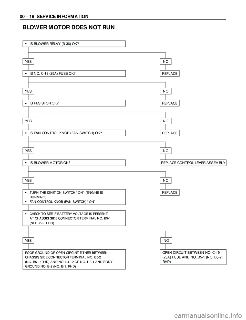
BLOWER MOTOR DOES NOT RUN
·IS NO. C-19 (25A) FUSE OK?
·IS BLOWER RELAY (B-36) OK?
YESNO
REPLACE
NO
REPLACE
NO
REPLACE
NO
REPLACE CONTROL LEVER ASSEMBLY
NO
REPLACE
NO
OPEN CIRCUIT BETWEEN NO. C-19
(25A) FUSE AND NO. B5-1 (NO. B5-2;
RHD)
YES
·IS RESISTOR OK?
YES
·IS FAN CONTROL KNOB (FAN SWITCH) OK?
YES
·IS BLOWER MOTOR OK?
YES
·TURN THE IGNITION SWITCH ÒONÓ (ENGINE IS
RUNNING)
·FAN CONTROL KNOB (FAN SWITCH) ÒONÓ
·CHECK TO SEE IF BATTERY VOLTAGE IS PRESENT
AT CHASSIS SIDE CONNECTOR TERMINAL NO. B5-1
(NO. B5-2; RHD)
YES
POOR GROUND OR OPEN CIRCUIT EITHER BETWEEN
CHASSIS SIDE CONNECTOR TERMINAL NO. B5-2
(NO. B5-1; RHD) AND NO. I-41-2 OR NO. I18-1 AND BODY
GROUND NO. B-2 (NO. B-1; RHD)
Page 60 of 3573

SERVICE INFORMATION 00 Ð 21
CERAMIC HEATER DOES NOT OPERATE
·ARE NO. FL-3 (40A) AND NO. C-20 (10A) OK?
YESNO
REPLACE
REPLACE
REPLACE
REPLACE
·ARE A/C AND CERAMIC HEATER RELAYS OK?
YESNO
·ARE BLOWER MOTOR AND FAN SW. OK?
YESNO
·IS FULL HOT SW. OK?
·DOES TEMP. CONTROL LINK (HEATER UNIT)
OPERATE CORRECTLY?
YESNO
REPLACE·TURN THE IGNITION SW. ÒONÓ (ENGINE IS RUNNING)·CERAMIC HEATER ÒONÓ
·CHECK TO SEE IF BATTERY VOLTAGE IS PRESENT AT
CHASSIS SIDE CONNECTOR TERMINAL NO. B48-1
YESNO
OPEN CIRCUIT·CHECK TO SEE IF BATTERY VOLTAGE IS PRESENT AT
CHASSIS SIDE CONNECTOR TERMINAL NO. B48-2
YESNO
CERAMIC HEATER DEFECTIVE·CHECK THE CERAMIC HEATER OR CERAMIC HEATER-
RELATED HARNESS FOR A POOR GROUND AND REPAIR
IT AS NECESSARY
YESNO
·DOES CONTROL LEVER CABLE OPERATE CORRECTLY?·IS THERMO RELAY OK?
YESNO
NOYES
ADJUST OR REPLACEREPAIR OR REPLACE
TEMP. CONTROL UNIT
Page 63 of 3573

00 Ð 24 SERVICE INFORMATION
CHECKING REFRIGERANT SYSTEM
WITH MANIFOLD GAUGE
Conditions;
·Ambient temperature at approx. 25 ~30°C (77
~86°F)
·Run the engine at Idling
·A/C switch is ÒONÓ
·Run the blower motor at Ò4Ó (high) position
·Temperature control knob sets at ÒMAX COLDÓ
·Air source selector lever at ÒCIRCÓ
·Close the all doors
Normal pressures kpa (kgácm
2/ PSI);
Low-pressure side:
Approx. 147 Ð 294 (1.5 Ð 3.0 / 21 Ð 43)
High-pressure side:
Approx. 1373 Ð 1863 (14 Ð 19 / 199 Ð 270 )
Connect the manifold gauge
Low-pressure hose (LOW)~Suction side
High-pressure hose (HI)~Discharge side (Low side) (High side)
Page 71 of 3573

00 Ð 32 SERVICE INFORMATION
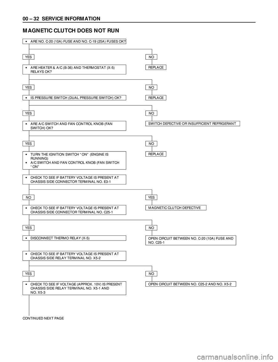
MAGNETIC CLUTCH DOES NOT RUN
·ARE NO. C-20 (10A) FUSE AND NO. C-19 (25A) FUSES OK?
YESNO
REPLACE·ARE HEATER & A/C (B-36) AND THERMOSTAT (X-5)
RELAYS OK?
YESNO
REPLACE·IS PRESSURE SWITCH (DUAL PRESSURE SWITCH) OK?
YESNO
SWITCH DEFECTIVE OR INSUFFICIENT REFRIGERANT·ARE A/C SWITCH AND FAN CONTROL KNOB (FAN
SWITCH) OK?
YESNO
REPLACE·TURN THE IGNITION SWITCH ÒONÓ (ENGINE IS
RUNNING)
·A/C SWITCH AND FAN CONTROL KNOB (FAN SWITCH
ÒONÓ
·CHECK TO SEE IF BATTERY VOLTAGE IS PRESENT AT
CHASSIS SIDE CONNECTOR TERMINAL NO. E3-1
NOYES
MAGNETIC CLUTCH DEFECTIVE ·CHECK TO SEE IF BATTERY VOLTAGE IS PRESENT AT
CHASSIS SIDE CONNECTOR TERMINAL NO. C25-1
YESNO
OPEN CIRCUIT BETWEEN NO. C-20 (10A) FUSE AND
NO. C25-1·DISCONNECT THERMO RELAY (X-5)
·CHECK TO SEE IF BATTERY VOLTAGE IS PRESENT AT
CHASSIS SIDE RELAY TERMINAL NO. X5-2
YESNO
OPEN CIRCUIT BETWEEN NO. C25-2 AND NO. X5-2 ·CHECK TO SEE IF VOLTAGE (APPROX. 10V) IS PRESENT
CHASSIS SIDE RELAY TERMINAL NO. X5-1 AND
NO. X5-3
CONTINUED NEXT PAGE
Page 82 of 3573

SERVICE INFORMATION 00 Ð 43
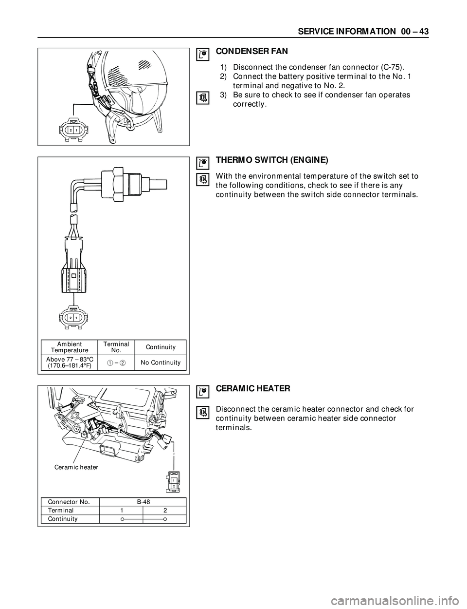
CONDENSER FAN
1 2
THERMO SWITCH (ENGINE)
1 2
1) Disconnect the condenser fan connector (C-75).
2) Connect the battery positive terminal to the No. 1
terminal and negative to No. 2.
3) Be sure to check to see if condenser fan operates
correctly.
With the environmental temperature of the switch set to
the following conditions, check to see if there is any
continuity between the switch side connector terminals.
Ambient Terminal
Continuity
Temperature No.
Above 77 Ð 83°C
1Ð 2No Continuity
(170.6Ð181.4°F)
CERAMIC HEATER
1
2
Ceramic heater
Disconnect the ceramic heater connector and check for
continuity between ceramic heater side connector
terminals.
Connector No. B-48
Terminal 1 2
Continuity