1998 ISUZU TROOPER check engine
[x] Cancel search: check enginePage 296 of 3573

00 – 14 SERVICE INFORMATION
STEERING WHEEL FREE PLAY
ADJUSTMENT
INSPECTION
1. Check the amount of steering wheel play by turning
the wheel in both directions until the tires begin to
move with the front wheels properly in the straight
ahead position.
NOTE:
The wheel free play should be checked with the engine
running.
Steering Wheel Free Play mm (in)
0 – 30 (0 – 1.18)
2. Also check the steering wheel for play and looseness
in mount by moving it back and froth and sideways.
While driving, check for hard-steering, steering
shimmy and tendency to pull to one side.
ADJUSTMENT
1. Align the front wheels properly in the straight ahead
position.
2. Loosen the lock nut on the adjusting screw of the
steering gear.
3. Turn the adjust screw clockwise to decrease free play
or counter-clockwise to increase.
4. After check of specified free play, tighten the lock nut
to specified torque.
Lock Nut Torque N·m (kg·m/lb·ft)
41 (4.2 / 30)
Page 312 of 3573

2A – 10 POWER STEERING
POWER STEERING SYSTEM TEST
TEST PROCEDURE
Test of fluid pressure in the power steering system
is performed to determine whether or not the oil
pump and power steering unit are functioning
normally.
The power steering system test is method used to
identify and isolate hydraulic circuit difficulties.
Prior to performing this test, the following
inspections and corrections, if necessary, must be
made.
INSPECT
•Pump reservoir for proper fluid level.
•Pump belt for proper tension.
•Pump driver pulley condition.
1. Place a container under the pump to catch the
fluid when disconnecting or connecting the
hoses.
2. With the engine NOT running , disconnect the
pressure hose at the power steering pump and
install Power Steering tester.
The gage must be between the shutoff valve
and pump. Open the shutoff valve.
Tester: 5-8840-0135-0 (J-29877-A)
Adapter: 5-8840-2297-0 (For 6VD1, 6VE1, 4JX1)
5-8840-0136-0 (For 4JG2)3. Check the fluid level. Fill the reservoir with
power steering fluid, to the “Full” mark. Start
the engine then turn the steering wheel and
momentarily hold it against a stop. Turn off
and check the connections at tester for leakage.
4. Bleed the system. Refer to “Bleeding the
Power Steering System” in this section.
5. Start the engine and check the pump fluid
level. Add power steering fluid if required.
When the engine is at normal operating
temperature, increase engine speed to 1500
rpm.
CAUTION:
Do not leave shutoff valve fully closed for more
than 5 seconds, as the pump could become
damaged internally.
6. Fully close the shutoff valve. Record the
highest pressures.
•If the pressure recorded is within 9300-9800
kPa (1350-1420 psi) For 6VD1, 6VE1, and
9800-10300 kPa (100-105 kg/cm
2/ 1420-1490
psi) For 4JG2, 4JX1, the pump is functioning
within its specifications.
•If the pressure recorded is higher than 9800
kPa (1420 psi) For 6VD1, 6VE1, and 10300
kPa (105 kg/cm
2/ 1490 psi) For 4JG2, 4JX1,
the valve in the pump is defective.
Page 313 of 3573
POWER STEERING 2A – 11
•If the pressure recorded is lower than 9300
kPa (1350 psi) For 6VD1, 6VE1, and 9800 kPa
(100 kg/cm
2/ 1420 psi) For 4JG2, 4JX1, the
valve or the rotating group in the pump is
defective.
7. If the pump pressure are within specifications,
leave the valve open and turn (or have
someone else turn) the steering wheel fully in
both directions. Record the highest pressures
and compare with the maximum pump
pressure recorded in step 6. If this pressure cannot be built in either (or one) side of the
power steering gear, the power steering gear is
leaking internally and must be disassembled
and repaired.
8. Shut the engine off, remove the testing gage,
reconnect the pressure hose, check the fluid
level and make the needed repairs.
9. If the problem still exists, the steering and front
suspension must be thoroughly examined.
Page 314 of 3573
BLEEDING THE POWER
STEERING SYSTEM
When a power steering pump or gear has been
installed, or an oil line has been disconnected, the
air that has entered the system must be bled out
before the vehicle is operated. If air is allowed to
remain in the power steering fluid system, noisy
and unsatisfactory operation of the system may
result.
BLEEDING PROCEDURE
When bleeding the system, and any time fluid is
added to the power steering system, be sure to use
only power steering fluid as specified in
“MAINTENANCE AND LUBRICATION” in section
0B.
1. Fill the pump fluid reservoir to the proper
level and let the fluid settle for at least two
minutes.
2. Start the engine and let it run for a few
seconds.
Do not turn the steering wheel. Then turn the
engine off.
3. Add fluid if necessary.
4. Repeat the above procedure until the fluid
level remains constant after running the
engine.
5. Raise the front end of the vehicle so that the
wheels are off the ground.
6. Start the engine. Slowly turn the steering
wheel right and left, lightly contacting the
wheel stops.
7. Add power steering fluid if necessary.
8. Bring down the vehicle, set the steering wheel
at the straight forward position after turning it
to its full steer positions 2 or 3 times, and stop
the engine.
9. Stop the engine. Check the fluid level and
refill as required.
10. If the fluid is extremely foamy, allow the
vehicle to stand a few minutes and repeat the
above procedure.
INSPECT
•Belt for tightness.
•Pulley for looseness or damage. The pulley
should not wobble with the engine running.
•Make sure that hose and pipes are properly
fitted.
•Fluid level and fill to the proper level.
FLUSHING THE POWER
STEERING SYSTEM
1. Raise the front end of the vehicle off the
ground until the wheels are free to turn.
2. Remove the fluid return line at the reservoir
inlet connector and plug the connector.
Position the line toward a large container to
catch the draining fluid.
3. While running the engine at idle, fill the
reservoir with new power steering fluid. Turn
the steering wheel in both directions. Do not
contact wheel stops or hold the wheel in a
corner, or fluid will stop and the pump will be
in pressure relief mode. A sudden overflow
from the reservoir may develop if the wheel is
held at a stop.
4. While refilling the reservoir, check the
draining fluid for contamination. If foreign
material is still evident, replace all lines,
disassemble and clean or replace the power
steering system components. Do not re-use
any drained power steering fluid.
5. Install all the lines and hoses. Fill the system
with new power steering fluid and bleed the
system as described in “Bleeding The Power
Steering System”. Operate the engine for
about 15 minutes. 2A – 12 POWER STEERING
ON-VEHICLE SERVICE
Page 470 of 3573
DIFFERENTIAL (REAR 220mm)
4A2A±3
Diagnosis
Many noises that seem to come from the rear axle
actually originate from other sources such as tires, road
surface, wheel bearings, engine, transmission, muffler, or
body drumming. Investigate to find the source of the
noise before disassembling the rear axle. Rear axles, like
any other mechanical device, are not absolutely quiet but
should be considered quiet unless some abnormal noise
is present.
To make a systematic check for axle noise, observe the
following:
1. Select a level asphalt road to reduce tire noise and
body drumming.
2. Check rear axle lubricant level to assure correct level,
and then drive the vehicle far enough to thoroughly
warm up the rear axle lubricant.
3. Note the speed at which noise occurs. Stop the
vehicle and put the transmission in neutral. Run the
engine speed slowly up and down to determine if the
noise is caused by exhaust, muffler noise, or other
engine conditions.
4. Tire noise changes with different road surfaces; axle
noises do not. Temporarily inflate all tires to 344 kPa
(3.5kg/cm
2, 50 psi) (for test purposes only). This will
change noise caused by tires but will not affect noise
caused by the rear axle.
Rear axle noise usually stops when coasting at
speeds under 48 km/h (30 mph); however, tire noise
continues with a lower tone. Rear axle noise usually
changes when comparing pull and coast, but tire
noise stays about the same.
Distinguish between tire noise and rear axle noise by
noting if the noise changes with various speeds or
sudden acceleration and deceleration. Exhaust and
axle noise vary under these conditions, while tire
noise remains constant and is more pronounced at
speeds of 32 to 48 km/h (20 to 30 mph). Further check
for tire noise by driving the vehicle over smooth
pavements or dirt roads (not gravel) with the tires at
normal pressure. If the noise is caused by tires, it will
change noticeably with changes in road surface.
5. Loose or rough front wheel bearings will cause noise
which may be confused with rear axle noise; however,
front wheel bearing noise does not change when
comparing drive and coast. Light application of the
brake while holding vehicle speed steady will often
cause wheel bearing noise to diminish. Front wheel
bearings may be checked for noise by jacking up the
wheels and spinning them or by shaking the wheels to
determine if bearings are loose.
6. Rear suspension rubber bushings and spring
insulators dampen out rear axle noise when correctly
installed. Check to see that there is no link or rod
loosened or metal±to±metal contact.
7. Make sure that there is no metal±to±metal contact
between the floor and the frame.
After the noise has been determined to be in the axle, the
type of axle noise should be determined, in order to make
any necessary repairs.
Gear Noise
Gear noise (whine) is audible from 32 to 89 km/h (20 to 55
mph) under four driving conditions.
1. Driving under acceleration or heavy pull.
2. Driving under load or under constant speed.
3. When using enough throttle to keep the vehicle from
driving the engine while the vehicle slows down
gradually (engine still pulls slightly).
4. When coasting with the vehicle in gear and the throttle
closed. The gear noise is usually more noticeable
between 48 and 64 km/h (30 and 40 mph) and 80 and
89 km/h (50 and 55 mph).
Bearing Noise
Bad bearings generally produce a rough growl or grating
sound, rather than the whine typical of gear noise.
Bearing noise frequently ªwow±wowsº at bearing rpm,
indicating a bad pinion or rear axle side bearing. This
noise can be confused with rear wheel bearing noise.
Rear Wheel Bearing Noise
Rear wheel bearing noise continues to be heard while
coasting at low speed with transmission in neutral. Noise
may diminish by gentle braking. Jack up the rear wheels,
spin them by hand and listen for noise at the hubs.
Replace any faulty wheel bearings.
Knock At Low Speeds
Low speed knock can be caused by worn universal joints
or a side gear hub counter bore in the cage that is worn
oversize. Inspect and replace universal joints or cage and
side gears as required.
Backlash Clunk
Excessive clunk on acceleration and deceleration can be
caused by a worn rear axle pinion shaft, a worn cage,
excessive clearance between the axle and the side gear
splines, excessive clearance between the side gear hub
and the counterbore in the cage, worn pinion and side
gear teeth, worn thrust washers, or excessive drive pinion
and ring gear backlash. Remove worn parts and replace
as required. Select close±fitting parts when possible.
Adjust pinion and ring gear backlash.
Page 506 of 3573
DIFFERENTIAL (REAR 244mm)
4A2B±3
Diagnosis
Many noises that seem to come from the rear axle
actually originate from other sources such as tires, road
surface, wheel bearings, engine, transmission, muffler, or
body drumming. Investigate to find the source of the
noise before disassembling the rear axle. Rear axles, like
any other mechanical device, are not absolutely quiet but
should be considered quiet unless some abnormal noise
is present.
To make a systematic check for axle noise, observe the
following:
1. Select a level asphalt road to reduce tire noise and
body drumming.
2. Check rear axle lubricant level to assure correct level,
and then drive the vehicle far enough to thoroughly
warm up the rear axle lubricant.
3. Note the speed at which noise occurs. Stop the
vehicle and put the transmission in neutral. Run the
engine speed slowly up and down to determine if the
noise is caused by exhaust, muffler noise, or other
engine conditions.
4. Tire noise changes with different road surfaces; axle
noises do not. Temporarily inflate all tires to 344 kPa
(3.5kg/cm
2, 50 psi) (for test purposes only). This will
change noise caused by tires but will not affect noise
caused by the rear axle.
Rear axle noise usually stops when coasting at
speeds under 48 km/h (30 mph); however, tire noise
continues with a lower tone. Rear axle noise usually
changes when comparing pull and coast, but tire
noise stays about the same.
Distinguish between tire noise and rear axle noise by
noting if the noise changes with various speeds or
sudden acceleration and deceleration. Exhaust and
axle noise vary under these conditions, while tire
noise remains constant and is more pronounced at
speeds of 32 to 48 km/h (20 to 30 mph). Further check
for tire noise by driving the vehicle over smooth
pavements or dirt roads (not gravel) with the tires at
normal pressure. If the noise is caused by tires, it will
change noticeably with changes in road surface.
5. Loose or rough front wheel bearings will cause noise
which may be confused with rear axle noise; however,
front wheel bearing noise does not change when
comparing drive and coast. Light application of the
brake while holding vehicle speed steady will often
cause wheel bearing noise to diminish. Front wheel
bearings may be checked for noise by jacking up the
wheels and spinning them or by shaking the wheels to
determine if bearings are loose.
6. Rear suspension rubber bushings and spring
insulators dampen out rear axle noise when correctly
installed. Check to see that there is no link or rod
loosened or metal±to±metal contact.
7. Make sure that there is no metal±to±metal contact
between the floor and the frame.
After the noise has been determined to be in the axle, the
type of axle noise should be determined, in order to make
any necessary repairs.
Gear Noise
Gear noise (whine) is audible from 32 to 89 km/h (20 to 55
mph) under four driving conditions.
1. Driving under acceleration or heavy pull.
2. Driving under load or under constant speed.
3. When using enough throttle to keep the vehicle from
driving the engine while the vehicle slows down
gradually (engine still pulls slightly).
4. When coasting with the vehicle in gear and the throttle
closed. The gear noise is usually more noticeable
between 48 and 64 km/h (30 and 40 mph) and 80 and
89 km/h (50 and 55 mph).
Bearing Noise
Bad bearings generally produce a rough growl or grating
sound, rather than the whine typical of gear noise.
Bearing noise frequently ªwow±wowsº at bearing rpm,
indicating a bad pinion or rear axle side bearing. This
noise can be confused with rear wheel bearing noise.
Rear Wheel Bearing Noise
Rear wheel bearing noise continues to be heard while
coasting at low speed with transmission in neutral. Noise
may diminish by gentle braking. Jack up the rear wheels,
spin them by hand and listen for noise at the hubs.
Replace any faulty wheel bearings.
Knock At Low Speeds
Low speed knock can be caused by worn universal joints
or a side gear hub counter bore in the cage that is worn
oversize. Inspect and replace universal joints or cage and
side gears as required.
Backlash Clunk
Excessive clunk on acceleration and deceleration can be
caused by a worn rear axle pinion shaft, a worn cage,
excessive clearance between the axle and the side gear
splines, excessive clearance between the side gear hub
and the counterbore in the cage, worn pinion and side
gear teeth, worn thrust washers, or excessive drive pinion
and ring gear backlash. Remove worn parts and replace
as required. Select close±fitting parts when possible.
Adjust pinion and ring gear backlash.
Page 537 of 3573
4B1±4
DRIVE LINE CONTROL SYSTEM (SHIFT ON THE FLY)
Inspection and Repair
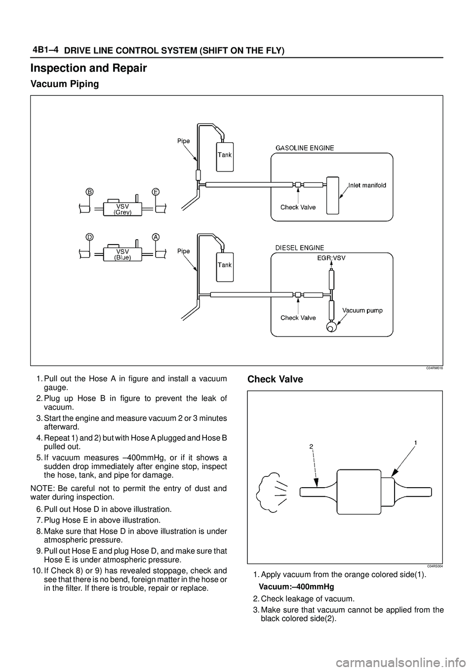
Vacuum Piping
C04RW016
1. Pull out the Hose A in figure and install a vacuum
gauge.
2. Plug up Hose B in figure to prevent the leak of
vacuum.
3. Start the engine and measure vacuum 2 or 3 minutes
afterward.
4. Repeat 1) and 2) but with Hose A plugged and Hose B
pulled out.
5. If vacuum measures ±400mmHg, or if it shows a
sudden drop immediately after engine stop, inspect
the hose, tank, and pipe for damage.
NOTE: Be careful not to permit the entry of dust and
water during inspection.
6. Pull out Hose D in above illustration.
7. Plug Hose E in above illustration.
8. Make sure that Hose D in above illustration is under
atmospheric pressure.
9. Pull out Hose E and plug Hose D, and make sure that
Hose E is under atmospheric pressure.
10. If Check 8) or 9) has revealed stoppage, check and
see that there is no bend, foreign matter in the hose or
in the filter. If there is trouble, repair or replace.Check Valve
C04RS004
1. Apply vacuum from the orange colored side(1).
Vacuum:±400mmHg
2. Check leakage of vacuum.
3. Make sure that vacuum cannot be applied from the
black colored side(2).
Page 538 of 3573
4B1±5 DRIVE LINE CONTROL SYSTEM (SHIFT ON THE FLY)
4. If vacuum is not applicable as much as ±400mmHg,
and if there is resistance on the intake side, replace
with a new check valve.
VSV Assembly
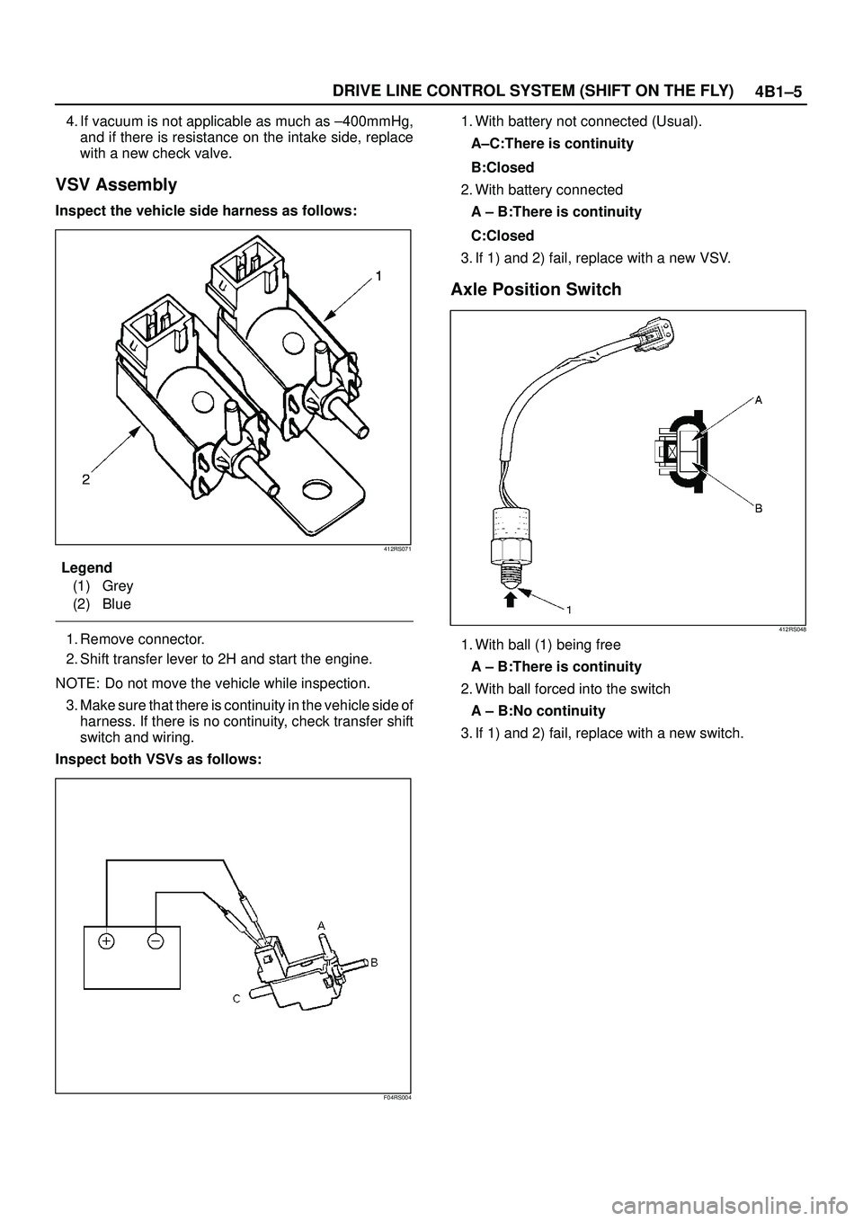
Inspect the vehicle side harness as follows:
412RS071
Legend
(1) Grey
(2) Blue
1. Remove connector.
2. Shift transfer lever to 2H and start the engine.
NOTE: Do not move the vehicle while inspection.
3. Make sure that there is continuity in the vehicle side of
harness. If there is no continuity, check transfer shift
switch and wiring.
Inspect both VSVs as follows:
F04RS004
1. With battery not connected (Usual).
A±C:There is continuity
B:Closed
2. With battery connected
A ± B:There is continuity
C:Closed
3. If 1) and 2) fail, replace with a new VSV.
Axle Position Switch
412RS048
1. With ball (1) being free
A ± B:There is continuity
2. With ball forced into the switch
A ± B:No continuity
3. If 1) and 2) fail, replace with a new switch.