1998 ISUZU TROOPER checking oil
[x] Cancel search: checking oilPage 260 of 3573
1D Ð 4 COMPRESSOR OVERHAUL
COMPRESSOR OIL
OIL SPECIFICATION
·The HFC-134a system requires a synthetic
(PAG) compressor oil.
·Compressor (PAG) oil varies according to
compressor model. Be sure to use oil specified
for the model of compressor.
DKV-14D : ZXL-200PG
(ISUZU PART NO.
8-97101-336-0)
DKS-15CH : ZXL-100PG
(ISUZU PART NO.
8-97101-338-0)
HANDLING OF OIL
·The oil should be free from moisture, dust,
metal powder, etc.
·Do not mix with other oil
·The water content in the oil increases when
exposed to the air. After use, seal oil from air
immediately.
·The compressor oil must be stored in steel
containers, not in plastic containers.
COMPRESSOR OIL CHECK
The oil used to lubricate the compressor is
circulating with the refrigerant.
Whenever replacing any component of the system
or a large amount of gas leakage occurs, add oil to
maintain the original amount of oil.
Oil Capacity
Capacity total in system 150cc (4.2 Imp fl oz)
Compressor (Service
150cc (4.2 Imp fl oz)
parts) charging amount
Checking and Adjusting for Used Compressor
1) Perform Oil return operation.
(Refer to ÒOil Return OperationÓ in this section.)
2) Discharge refrigerant and remove the
compressor.
3) Drain the compressor oil and measure the
extracted oil with a measuring cylinder.
4) If the amount of oil drained is much less than
90cc (2.5 Imp fl oz), some refrigerant may have
leaked out. Conduct leak tests on connections
of each system, and if necessary, repair or
replace faulty parts.5) Check the compressor oil for contamination.
(Refer to ÒContamination of Compressor OilÓ in
this section.)
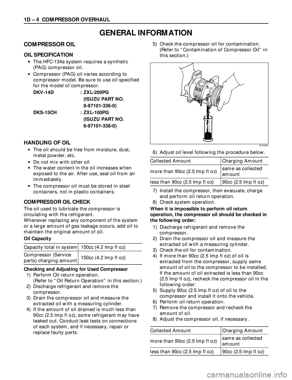
6) Adjust oil level following the procedure below.
Collected Amount Charging Amount
same as collected
more than 90cc (2.5 Imp fl oz)
amount
less than 90cc (2.5 Imp fl oz) 90cc (2.5 Imp fl oz)
7) Install the compressor, then evacuate, charge
and perform oil return operation.
8) Check system operation.
When it is impossible to perform oil return
operation, the compressor oil should be checked in
the following order:
1) Discharge refrigerant and remove the
compressor.
2) Drain the compressor oil and measure the
extracted oil with a measuring cylinder.
3) Check the oil for contamination.
4) If more than 90cc (2.5 Imp fl oz) of oil is
extracted from the compressor, supply same
amount of oil to the compressor to be installed.
If the amount of oil extracted is less than 90cc
(2.5 Imp fl oz), recheck the compressor oil in the
following order:
5) Supply 90cc (2.5 Imp fl oz) of oil to the
compressor and install it onto the vehicle.
6) Perform oil return operation.
7) Remove the compressor and recheck the
amount of oil.
8) Adjust the compressor oil, if necessary.
Collected Amount Charging Amount
same as collected
more than 90cc (2.5 Imp fl oz)
amount
less than 90cc (2.5 Imp fl oz) 90cc (2.5 Imp fl oz)
GENERAL INFORMATION
871RX020
Page 261 of 3573
COMPRESSOR OVERHAUL 1D Ð 5
Checking and Adjusting for Compressor
Replacement
150cc (4.2 Imp fl oz) of oil is charged in compressor
(service parts). So it is necessary to drain the proper
amount of oil from the new compressor.
1) Perform oil return operation.
2) Discharge refrigerant and remove the
compressor.
3) Drain the compressor oil and measure the
extracted oil.
4) Check the compressor oil for contamination.
5) Adjust oil level as required.
Amount of oil drained Draining amount of oil
from used compressor from new compressor
less than Same as drained
90cc (2.5 Imp fl oz) amount
more than
90cc (2.5 Imp fl oz)
90cc (2.5 Imp fl oz)
6) Evacuate, charge and perform oil return
operation.
7) Check system operation.
CONTAMINATION OF COMPRESSOR OIL
Unlike engine oil, no cleaning agent is added to the
compressor oil. Even if the compressor runs for a
long period of time (approximately 1 season), the
oil never becomes contaminated as long as there is
nothing wrong with the compressor or its method
of use.
Inspect the extracted oil for any of the following
conditions:
·The capacity of the oil has increased.
·The oil has changed color to red.
·Foreign substances, metal powder, etc., are
present in the oil.
If any of these conditions exists, compressor oil is
contaminated. Whenever contaminated
compressor oil is discovered, the receiver/drier
must be replaced.
OIL RETURN OPERATION
There is close affinity between the oil and the
refrigerant. During normal operation, part of the oil
recirculates with the refrigerant in the system.
When checking the amount of oil in the system, or
replacing any component of the system, the
compressor must be run in advance for oil return
operation. The procedure is as follows:
1) Open the all doors and engine hood.
2) Start the engine and A/C switch is ÒONÓ and
Set the fan control knob at its highest position.
3) Run the compressor for more than 20 minutes
between 800 and 1,000 rpm in order to operate
the system.
4) Stop the engine.
REPLACEMENT OF COMPONENT PARTS
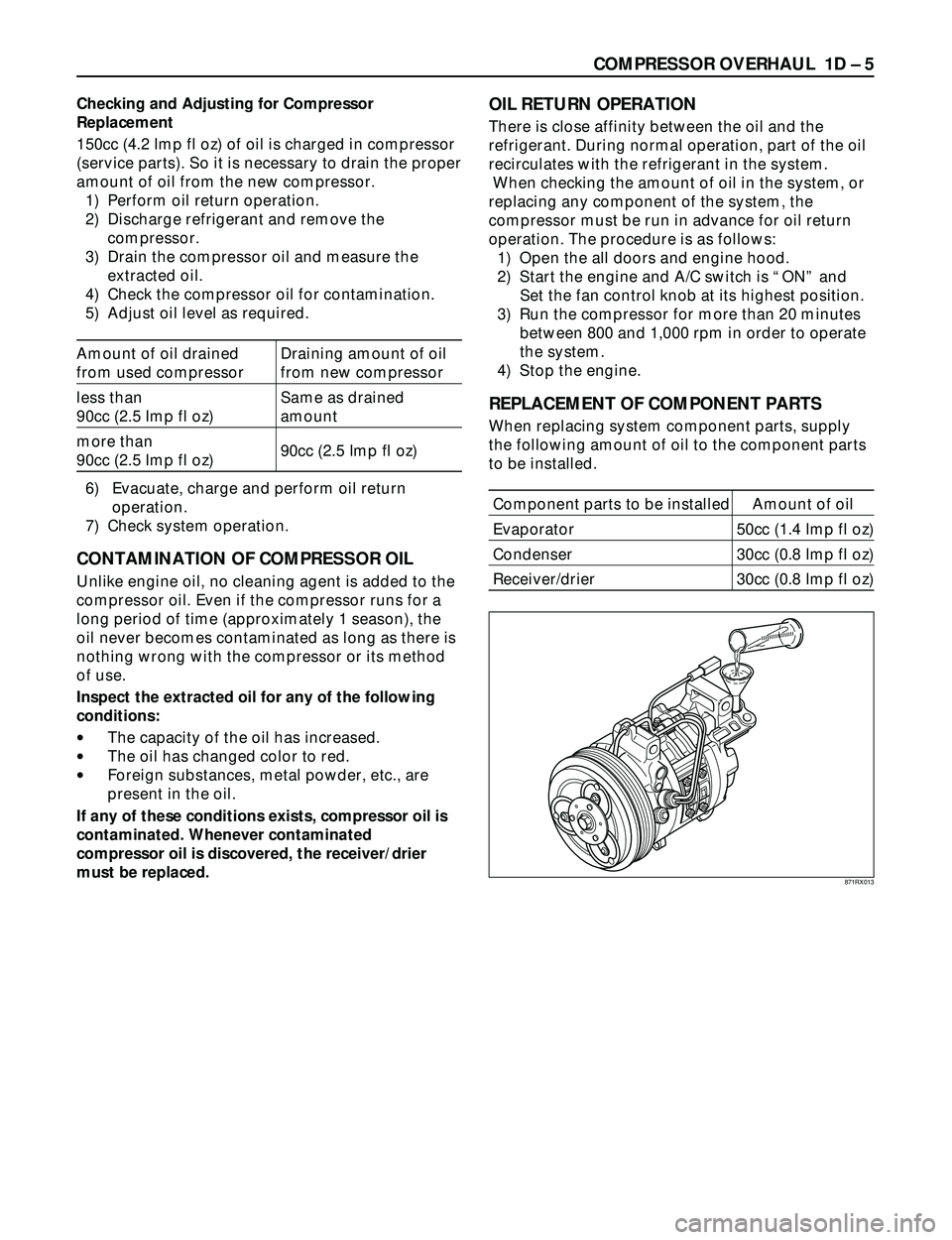
When replacing system component parts, supply
the following amount of oil to the component parts
to be installed.
Component parts to be installed Amount of oil
Evaporator 50cc (1.4 Imp fl oz)
Condenser 30cc (0.8 Imp fl oz)
Receiver/drier 30cc (0.8 Imp fl oz)
871RX013
Page 280 of 3573
1D Ð 24 COMPRESSOR OVERHAUL
6. Remove any excess oil resulting from installing the
new seal parts from the shaft and inside the
compressor neck.
7. Install the clutch plate and hub assembly as
described previously.8. Reinstall compressor belt and tighten bracket.
9. Evacuate and charge the refrigerant system.
COMPRESSOR PRESSURE RELIEF VALVE
Removal
1. Recover the refrigerant using Refrigerant Recovery
System.
2. Remove old pressure relief valve.
Installation
1. Clean valve seat area on rear head.2. Lubricate O-ring of new pressure relief valve and
O-ring assembly with new 525 viscosity refrigerant
oil. Install new valve and torque in place, 9.0 Nám
(6.1 ft lbs)
3. Evacuate and recharge the system.
4. Leak test system.
COMPRESSOR OIL
Compressor Oil Check
The oil used to lubricate the compressor is circulating
with the refrigerant.
Whenever replacing any component of the system or a
large amount of gas leakage occurs, add oil to maintain
the original amount of oil.
Checking and Adjusting Oil Quantity for
Used Compressor
1. Perform oil return operation. Refer to Oil Return
Operation in this section.
2. Discharge and recover refrigerant and remove the
compressor.
3. Drain the compressor oil and measure the extracted
oil with a measuring cylinder.
4. If the amount of oil drained is much less than 90 cc
(3.0 fl. oz.), some refrigerant may have leaked out.
Conduct a leak tests on the connections of each
system, and if necessary, repair or replace faulty
parts.
5. Check the compressor oil contamination. (Refer to
Contamination of Compressor Oil in this section.)
6. Adjust the oil level following the next procedure
below.7. Install the compressor, then evacuate, charge and
perform the oil return operation.
8. Check system operation.
When it is impossible to preform oil return
operation, the compressor oil should be checked in
the following order:
1. Discharge and recover refrigerant and remove the
compressor.
2. Drain the compressor oil and measure the extracted
oil with a measuring cylinder.
3. Check the oil for contamination.
4. If more than 90 cc (3.0 fl. oz.) of oil is extracted from
the compressor, supply the same amount of oil to
the compressor to be installed. If the amount of oil
extracted is less than 90 cc (3.0 fl. oz.), recheck the
compressor oil in the following order:
5. Supply 90 cc (3.0 fl. oz.) of oil to the compressor
and install it onto the vehicle.
6. Evacuate and recharge with the proper amount of
refrigerant.
7. Perform the oil return operation.
8. Remove the compressor and recheck the amount of
oil.
9. Adjust the compressor oil, if necessary.
Checking and Adjusting for Compressor
Replacement
The oil is not charged in compressor (service parts). So
it is necessary to charge the proper amount of oil to the
new compressor. (Oil Capacity)
Capacity total in system 150 cc (5.0 fl.oz)
Compressor (Service 150 cc (5.0 fl.oz)
parts) charging amount
(Collected Amount) (Charging Amount)
more than 90 cc same as collected
(3.0 fl.oz) amount
less than 90 cc (3.0 fl.oz) 90 cc (3.0 fl.oz)
(Collected Amount) (Charging Amount)
more than 90 cc same as collected
(3.0 fl.oz) amount
less than 90 cc (3.0 fl.oz) 90 cc (3.0 fl.oz)
Page 281 of 3573
COMPRESSOR OVERHAUL 1D Ð 25
1. Perform oil return operation.
2. Discharge and recover the refrigerant and remove
the compressor.
3. Drain the compressor oil and measure the extracted
oil.
4. Check the compressor oil for contamination.
5. Adjust the oil level as required.
6. Evacuate, charge and perform the oil return
operation.
7. Check the system operation.
Contamination of Compressor Oil
Unlike engine oil, no cleaning agent is added to the
compressor oil. Even if the compressor runs for a long
period of time (approximately one season), the oil never
becomes contaminated as long as there is nothing
wrong with the compressor or its method of use.
Inspect the extracted oil for any of the following
conditions:
·The capacity of the oil has increased.
·The oil has changed to red.
·Foreign substances, metal powder, etc., are present
in the oil.
If any of these conditions exists, the compressor
oil is contaminated. Whenever contaminated
compressor oil is discovered, the receiver/drier
must be replaced.
Oil Return Operation
There is close affinity between the oil and the
refrigerant. During normal operation, part of the oil
recirculates with the refrigerant in the system. When
checking the amount of oil in the system, or replacing
any component of the system, the compressor must be
run in advance for oil return operation. The procedure
is as follows:
1. Open all the doors and the engine hood.
2. Start the engine and air conditioning switch to "ON"
and set the fan control knob at its highest position.
3. Run the compressor for more than 20 minutes
between 800 and 1,000 rpm in order to operate the
system.
4. Stop the engine.
Replacement of Component Parts
When replacing the system component parts, supply
the following amount of oil to the component parts to be
installed.
Compressor Leak Testing (External and
Internal)
Bench-Check Procedure
1. Install test plate J-39893 on rear head of compressor.
2. Using Refrigerant Recovery System, attach center
hose of manifold gage set on charging station to a
refrigerant drum standing in an upright drum.
3. Connect charging station high and low pressure
lines to corresponding fittings on test plate J-39893.
Suction port (low-side) of compressor has large
internal opening. Discharge port (high-side) has
smaller internal opening into compressor and
deeper recess.
4. Open low pressure control, high pressure control
and refrigerant control on charging station to allow
refrigerant vapor to flow into compressor.
5. Using a leak detector, check for leaks at pressure
relief valve, rear head switch location, compressor
front and rear head seals, center cylinder seal,
through bolt head gaskets and compressor shaft
seal. After checking, shut off low pressure control
and high-pressure control on charging station.
6. If an external leak is present, perform the necessary
corrective measures and recheck for leaks to make
certain the leak has been connected.
7. Recover the refrigerant.
8. Disconnect both hoses from the test plate J-39893.
9. Add 90 ml (3 oz.) new PAG lubricant to the
compressor assembly. Rotate the complete
compressor assembly (not the crankshaft or drive
plate hub) slowly several turns to distribute oil to all
cylinder and piston areas.
10. Install a M9 ´1.25 threaded nut on the compressor
crankshaft if the drive plate and clutch assembly are
not installed.
11. Using a box-end wrench or socket and handle,
rotate the compressor crankshaft or clutch drive
plate on the crankshaft several turns to insure
piston assembly to cylinder wall lubrication.
12. Using Refrigerant Recovery System, connect the
charging station high-pressure line to the test plate
J-39893 high-side connector.
13. Using Refrigerant Recovery System, connect the
charging station low-pressure line to the low
pressure port of the test plate J-39893. Oil will drain
out of the compressor suction port if the compressor
is positioned with the suction port downward. (Component parts to be (Amount of Oil)
installed)
Evaporator 50 cc (1.7 fl. oz.)
Condenser 30 cc (1.0 fl. oz.)
Receiver/dryer 30 cc (1.0 fl. oz.)
Refrigerant line (one 10 cc (0.3 fl. oz.)
piece)
(Amount of oil drained (Charging amount of oil
from used compressor) to new compressor)
more than 90 cc same as drained amount
(3.0 fl.oz)
less than 90 cc (3.0 fl.oz) 90 cc (3.0 fl.oz)
Page 295 of 3573

SERVICE INFORMATION 00 – 13
STEERING
INSPECTION
Visual check
Check the following parts:
• Oil leakage.
• Steering system for looseness or damage.
• Steering function
• Joint ball for oil leakage or damage.
• Joint ball rubber boot for damage.
MAINTENANCE
The hydraulic system should be kept clean and fluid level
in the reservoir should be checked at regular intervals and
fluid added when required. Refer to "MAINTENANCE AND
LUBRICATION" in section 0B of the manual for type of
fluid to be used and intervals for filling.
If the system contains some dirt, flush it as detailed later
in this section. If it is exceptionally dirty, both the pump
and the gear must be completely disassembled before
further usage.
All tubes, hoses, and fittings should be inspected for
leakage at regular intervals. Fittings must be tight. Make
sure the clips, clamps and supporting tubes and hoses are
in place and properly secured.
Power steering hoses and lines must not be twisted,
kinked or tightly bent. Air in the system will cause spongy
action and noisy operation. When a hose is disconnected
or when fluid is lost, for any reason, the system must be
bled after refilling. Refer to "Bleeding the Power Steering
System" in this section.
FLUID LEVEL
1. Run the engine until the power steering fluid reaches
normal operating temperature, about 55°C (130°F),
then shut the engine off.
2. Check the level of fluid in the reservoir.
3. If the fluid level is low, add power steering fluid as
specified in "MAINTENANCE AND LUBRICATION" in
section 0B to the proper level and install the receiver
cap.
4. When checking the fluid level after the steering
system has been serviced, air must be bled from the
system. Refer to "Bleeding the Power Steering
System" in this section.
SERVICING
Page 671 of 3573
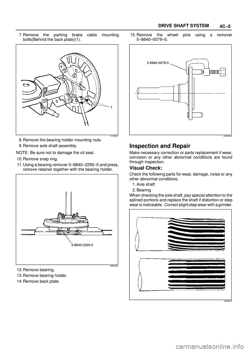
4C±5 DRIVE SHAFT SYSTEM
7. Remove the parking brake cable mounting
bolts(Behind the back plate)(1).
311RS001
8. Remove the bearing holder mounting nuts.
9. Remove axle shaft assembly.
NOTE: Be sure not to damage the oil seal.
10. Remove snap ring.
11. Using a bearing remover 5±8840±2295±0 and press,
remove retainer together with the bearing holder.
420RW024
12. Remove bearing.
13. Remove bearing holder.
14. Remove back plate.15. Remove the wheel pins using a remover
5±8840±0079±0.
420RW023
Inspection and Repair
Make necessary correction or parts replacement if wear,
corrosion or any other abnormal conditions are found
through inspection.
Visual Check:
Check the following parts for wear, damage, noise or any
other abnormal conditions:
1. Axle shaft
2. Bearing
When checking the axle shaft, pay special attention to the
splined portions and replace the shaft if distortion or step
wear is noticeable. Correct slight step wear with a grinder.
420RS008
Page 944 of 3573
5C – 66 POWER ASSISTED BRAKE SYSTEM
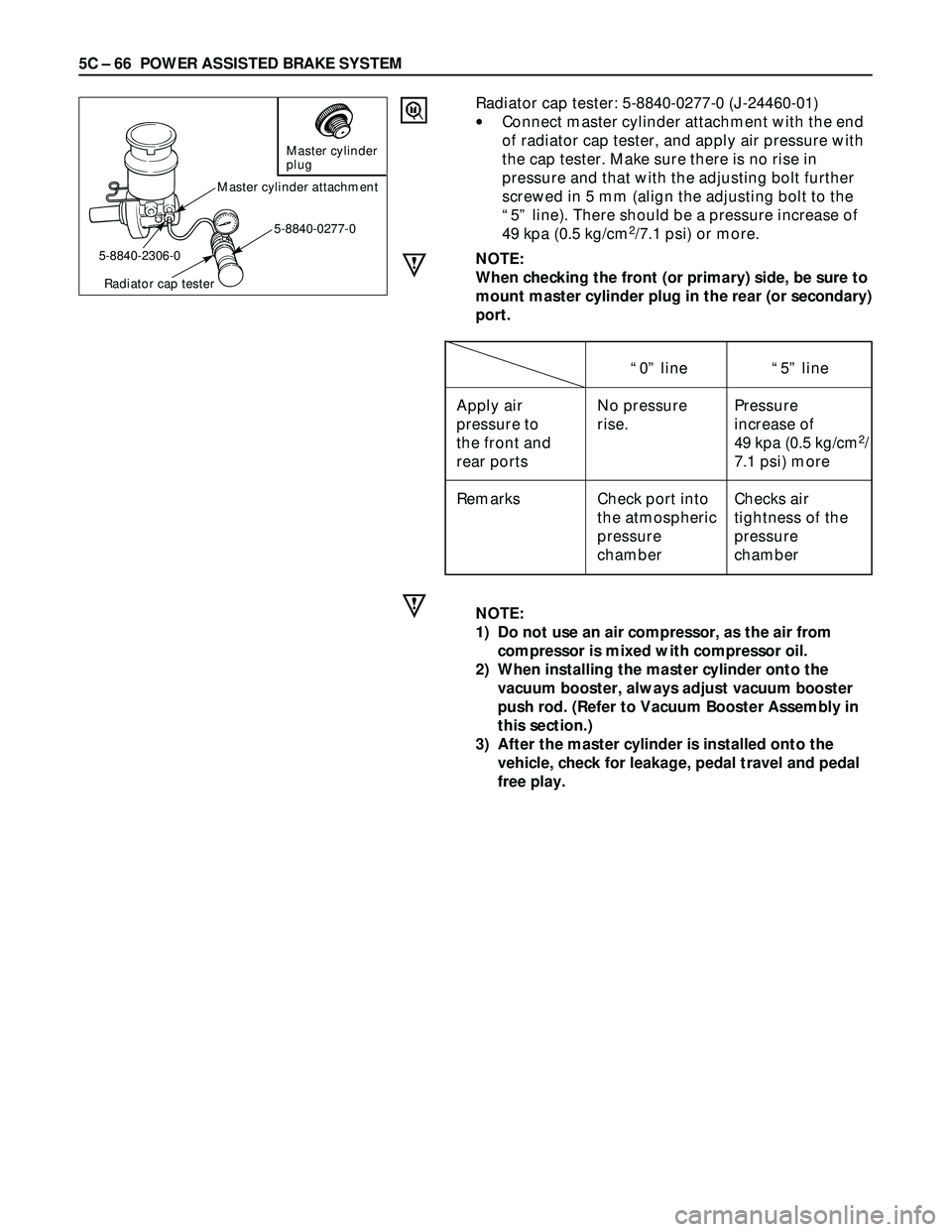
Radiator cap tester: 5-8840-0277-0 (J-24460-01)
•Connect master cylinder attachment with the end
of radiator cap tester, and apply air pressure with
the cap tester. Make sure there is no rise in
pressure and that with the adjusting bolt further
screwed in 5 mm (align the adjusting bolt to the
“5” line). There should be a pressure increase of
49 kpa (0.5 kg/cm
2/7.1 psi) or more.
NOTE:
When checking the front (or primary) side, be sure to
mount master cylinder plug in the rear (or secondary)
port.
NOTE:
1) Do not use an air compressor, as the air from
compressor is mixed with compressor oil.
2) When installing the master cylinder onto the
vacuum booster, always adjust vacuum booster
push rod. (Refer to Vacuum Booster Assembly in
this section.)
3) After the master cylinder is installed onto the
vehicle, check for leakage, pedal travel and pedal
free play.
Master cylinder
plug
Master cylinder attachment
5-8840-0277-0
Radiator cap tester
5-8840-2306-0
“0” line“5” line
Apply air No pressure Pressure
pressure to rise. increase of
the front and
49 kpa (0.5 kg/cm2/
rear ports 7.1 psi) more
Remarks Check port into Checks air
the atmospheric tightness of the
pressure pressure
chamber chamber
Page 1109 of 3573
6D3±18STARTING AND CHARGING SYSTEM
Charging System
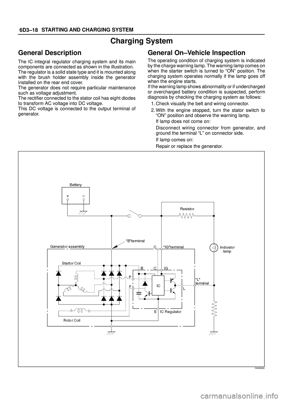
General Description
The IC integral regulator charging system and its main
components are connected as shown in the illustration.
The regulator is a solid state type and it is mounted along
with the brush holder assembly inside the generator
installed on the rear end cover.
The generator does not require particular maintenance
such as voltage adjustment.
The rectifier connected to the stator coil has eight diodes
to transform AC voltage into DC voltage.
This DC voltage is connected to the output terminal of
generator.
General On±Vehicle Inspection
The operating condition of charging system is indicated
by the charge warning lamp. The warning lamp comes on
when the starter switch is turned to ªONº position. The
charging system operates normally if the lamp goes off
when the engine starts.
If the warning lamp shows abnormality or if undercharged
or overcharged battery condition is suspected, perform
diagnosis by checking the charging system as follows:
1. Check visually the belt and wiring connector.
2. With the engine stopped, turn the stator switch to
ªONº position and observe the warning lamp.
If lamp does not come on:
Disconnect wiring connector from generator, and
ground the terminal ªLº on connector side.
If lamp comes on:
Repair or replace the generator.
F06RW009