1998 ISUZU TROOPER tire type
[x] Cancel search: tire typePage 21 of 3573

GENERAL INFORMATION 0AÐ7
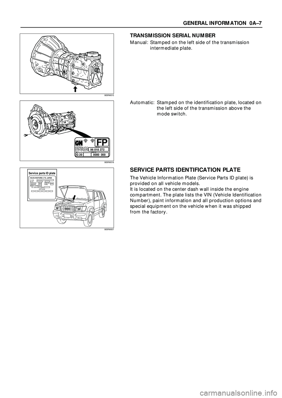
TRANSMISSION SERIAL NUMBER
Manual: Stamped on the left side of the transmission
intermediate plate.
Automatic: Stamped on the identification plate, located on
the left side of the transmission above the
mode switch.
96
0000 000018PART No.
SERIAL No. SALHYDRAMATIC
STRASBOURGMADE IN FRANCEG 20272
FP
SERVICE PARTS IDENTIFICATION PLATE
The Vehicle Information Plate (Service Parts ID plate) is
provided on all vehicle models.
It is located on the center dash wall inside the engine
compartment. The plate lists the VIN (Vehicle Identification
Number), paint information and all production options and
special equipment on the vehicle when it was shipped
from the factory.
Service parts ID plateISUZU MOTORS L T D. JAPAN
V.I.N.
M.D.
ENGINE
GRADETRANS.
TIRE
BODY TYPE
B. COLOR/TRIM
OPTION
905RW015
905RW018
905RW007
Page 304 of 3573

2A – 2 FRONT END ALIGNMENT
GENERAL DESCRIPTION
“Front End Alignment” refers to the angular relationship between the front wheels, the front suspension
attaching parts and the ground.
Proper front end alignment must be maintained in order to insure efficient steering, good directional
stability and to prevent abnormal tire wear.
The most important factors of front end alignment are wheel toe-in, wheel camber and axle caster.
DEFINITION OF TERMS
CAMBER
Camber is the inward or outward tilting of the front wheels
from the vertical. When the wheels tilt outward at the top,
the camber is positive (+). When the wheels tilt inward at
the top, the camber is negative (–). The amount of tilt
measured in degrees from the vertical is called the camber
angle.
If camber is extreme or unequal between the wheels,
improper steering and excessive tire wear will result.
Negative camber causes wear on the inside tire, while
positive camber causes wear to the outside.
CASTER
Caster is the tilting of the wheel axis either forward or
backward from the vertical (when viewed from the side of
the vehicle). A backward tilt is positive(+) and a forward tilt
is negative(–).
On the short and long arm type suspension you cannot
see a caster angle without a special instrument, but if you
look straight down from the top of the upper control arm
to the ground, the ball joints do not line up (fore and aft)
when a caster angle other than 0 degree is present. With a
positive angle, the lower ball joint would be slightly ahead
(toward the front of the vehicle) of the upper ball joint
center line.
TOE-IN
Toe-in is the turning of the front wheels. The actual
amount of toe-in is normally a fraction of a degree. Toe-in
is measured from the center of the tire treads or from the
inside of the tires. The purpose of toe-in is to insure
parallel rolling of the front wheels and to offset any small
deflections of the wheel support system which occurs
when the vehicle is rolling forward. Incorrect toe-in results
in excessive toe-in and unstable steering. Toe-in is the last
alignment to be set in the front end alignment procedure.
Page 433 of 3573

3E – 2 WHEELS AND TIRES
GENERAL DESCRIPTION
Replacement wheels or tires must be equivalent to
the originals in load capacity, specified dimension
and mounting configuration. Improper size or type
may affect bearing life, brake performance,
speedometer/odometer calibration, vehicle ground
clearance and tire clearance to the body and
chassis.All models are equipped with metric sized steel
belted radial tires. Correct tire pressures and
driving habits have an important influence on tire
life. Heavy cornering, excessively rapid
acceleration and unnecessary sharp braking
increase premature and uneven wear.
Page 435 of 3573

3E – 4 WHEELS AND TIRES
TIRES
REPLACEMENT
When replacement is necessary, the original metric size
should be used. Most metric tire sizes do not have exact
corresponding alphanumeric tire sizes. It is recommended
that new tires be installed in pairs on the same axle. If
necessary to replace only one tire, it should be paired with
tire having the most tread, to equalize braking traction.
CAUTION:
Do not mix different types of tires such as radial, bias and
bias-belted tires except in emergencies, because vehicle
handling may be seriously affected and may result in loss
of control.
TIRE MOUNTING
Remove valve cap on valve stem and deflate the tire.
Then use a tire changing machine to mount or dismount
tires.
Follow the equipment manufacturer’s instruction. Do not
use hand tools or tire lever alone to change tires as they
may damage the tire beads or wheel rim.
TIRE DISMOUNTING
Rim bead seats should be cleaned with a wire brush or
coarse steel wool to remove lubricants, and light rust.
Before mounting a tire, the bead area should be well
lubricated with an approved tire lubricant.
After mounting, inflate the tire to 196 kPa (28 psi) so that
beads are completely seated. Inflate the air to specified
pressure and install valve cap to the stem
WARNING:
NEVER STAND OVER TIRE WHEN INFLATING. BEAD MAY
BREAK WHEN BEAD SNAPS OVER RIM’S SAFETY HUMP
AND CAUSE SERIOUS PERSONAL INJURY.
NEVER EXCEED 240 kPa (35 psi) PRESSURE WHEN
INFLATING. IF 240 kPa (35 psi) PRESSURE WILL NOT
SEAT BEADS, DEFLATE, RE-LUBRICATE AND RE-INFLATE.
OVER INFLATION MAY CAUSE THE BEAD TO BREAK AND
CAUSE SERIOUS PERSONAL INJURY.
TIRE REPAIR
There are many different materials on the market used to
repair tires.
Manufacturers have published detailed instructions on
how and when to repair tires. These instructions can be
obtained from the tire manufacturer if they are not
included with the repair kit.
UNIT REPAIR
Page 436 of 3573

WHEELS AND TIRES 3E – 5
WHEELS
REPLACEMENT
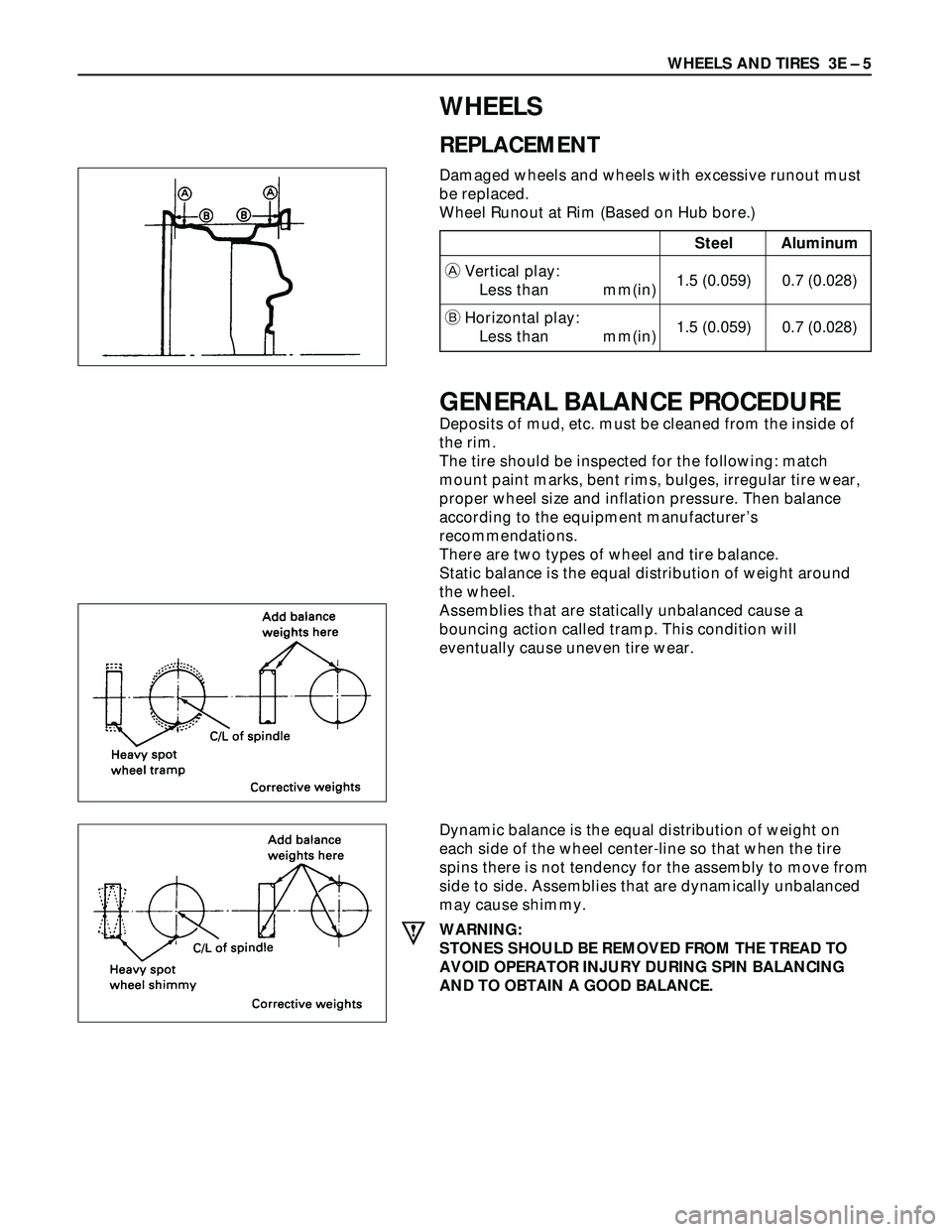
Damaged wheels and wheels with excessive runout must
be replaced.
Wheel Runout at Rim (Based on Hub bore.)
GENERAL BALANCE PROCEDURE
Deposits of mud, etc. must be cleaned from the inside of
the rim.
The tire should be inspected for the following: match
mount paint marks, bent rims, bulges, irregular tire wear,
proper wheel size and inflation pressure. Then balance
according to the equipment manufacturer’s
recommendations.
There are two types of wheel and tire balance.
Static balance is the equal distribution of weight around
the wheel.
Assemblies that are statically unbalanced cause a
bouncing action called tramp. This condition will
eventually cause uneven tire wear.
Dynamic balance is the equal distribution of weight on
each side of the wheel center-line so that when the tire
spins there is not tendency for the assembly to move from
side to side. Assemblies that are dynamically unbalanced
may cause shimmy.
WARNING:
STONES SHOULD BE REMOVED FROM THE TREAD TO
AVOID OPERATOR INJURY DURING SPIN BALANCING
AND TO OBTAIN A GOOD BALANCE.
Steel Aluminum
AVertical play:
Less than mm(in)1.5 (0.059) 0.7 (0.028)
BHorizontal play:
Less than mm(in)1.5 (0.059) 0.7 (0.028)
Page 469 of 3573

4A2A±2
DIFFERENTIAL (REAR 220mm)
General Description
The rear axle assembly is of the semi±floating type in
which the vehicle weight is carried on the axle housing .
The center line of the pinion gear is below the center line
of the ring gear (hypoid drive).
All parts necessary to transmit power from the propeller
shaft to the rear wheels are enclosed in a banjo type axle
housing.
The 8.7 inch ring gear rear axle uses a conventional ring
and pinion gear set to transmit the driving force of the
engine to the rear wheels. This gear set transfers thisdriving force at a 90 degree angle from the propeller shaft
to the drive shafts.
The axle shafts are supported at the wheel end of the
shaft by a roller bearing.
The pinion gear is supported by two tapered roller
bearings. The pinion depth is set by a shim pack located
between the gear end of the pinion and the roller bearing
that is pressed onto the pinion. The pinion bearing
preload is set by crushing a collapsible spacer between
the bearings in the axle housing.
A04RS001
The ring gear is bolted onto the differential cage with 12
bolts.
The differential cage is supported in the axle housing by
two tapered roller bearings. The differential and ring gear
are located in relationship to the pinion by using selective
shims and spacers between the bearing and the axle
housing. To move the ring gear, shims are deleted from
one side and an equal amount are added to the other side.
These shims are also used to preload the bearings whichare pressed onto the differential cage. Two bearing caps
are used to hold the differential into the rear axle housing.
The differential is used to allow the wheels to turn at
different rates of speed while the rear axle continues to
transmit the driving force. This prevents tire scuffing
when going around corners and prevents premature wear
on internal axle parts.
The rear axle is sealed with a pinion seal, a seal at each
axle shaft end, and by a liquid gasket between the
differential carrier and the axle housing.
Page 470 of 3573

DIFFERENTIAL (REAR 220mm)
4A2A±3
Diagnosis
Many noises that seem to come from the rear axle
actually originate from other sources such as tires, road
surface, wheel bearings, engine, transmission, muffler, or
body drumming. Investigate to find the source of the
noise before disassembling the rear axle. Rear axles, like
any other mechanical device, are not absolutely quiet but
should be considered quiet unless some abnormal noise
is present.
To make a systematic check for axle noise, observe the
following:
1. Select a level asphalt road to reduce tire noise and
body drumming.
2. Check rear axle lubricant level to assure correct level,
and then drive the vehicle far enough to thoroughly
warm up the rear axle lubricant.
3. Note the speed at which noise occurs. Stop the
vehicle and put the transmission in neutral. Run the
engine speed slowly up and down to determine if the
noise is caused by exhaust, muffler noise, or other
engine conditions.
4. Tire noise changes with different road surfaces; axle
noises do not. Temporarily inflate all tires to 344 kPa
(3.5kg/cm
2, 50 psi) (for test purposes only). This will
change noise caused by tires but will not affect noise
caused by the rear axle.
Rear axle noise usually stops when coasting at
speeds under 48 km/h (30 mph); however, tire noise
continues with a lower tone. Rear axle noise usually
changes when comparing pull and coast, but tire
noise stays about the same.
Distinguish between tire noise and rear axle noise by
noting if the noise changes with various speeds or
sudden acceleration and deceleration. Exhaust and
axle noise vary under these conditions, while tire
noise remains constant and is more pronounced at
speeds of 32 to 48 km/h (20 to 30 mph). Further check
for tire noise by driving the vehicle over smooth
pavements or dirt roads (not gravel) with the tires at
normal pressure. If the noise is caused by tires, it will
change noticeably with changes in road surface.
5. Loose or rough front wheel bearings will cause noise
which may be confused with rear axle noise; however,
front wheel bearing noise does not change when
comparing drive and coast. Light application of the
brake while holding vehicle speed steady will often
cause wheel bearing noise to diminish. Front wheel
bearings may be checked for noise by jacking up the
wheels and spinning them or by shaking the wheels to
determine if bearings are loose.
6. Rear suspension rubber bushings and spring
insulators dampen out rear axle noise when correctly
installed. Check to see that there is no link or rod
loosened or metal±to±metal contact.
7. Make sure that there is no metal±to±metal contact
between the floor and the frame.
After the noise has been determined to be in the axle, the
type of axle noise should be determined, in order to make
any necessary repairs.
Gear Noise
Gear noise (whine) is audible from 32 to 89 km/h (20 to 55
mph) under four driving conditions.
1. Driving under acceleration or heavy pull.
2. Driving under load or under constant speed.
3. When using enough throttle to keep the vehicle from
driving the engine while the vehicle slows down
gradually (engine still pulls slightly).
4. When coasting with the vehicle in gear and the throttle
closed. The gear noise is usually more noticeable
between 48 and 64 km/h (30 and 40 mph) and 80 and
89 km/h (50 and 55 mph).
Bearing Noise
Bad bearings generally produce a rough growl or grating
sound, rather than the whine typical of gear noise.
Bearing noise frequently ªwow±wowsº at bearing rpm,
indicating a bad pinion or rear axle side bearing. This
noise can be confused with rear wheel bearing noise.
Rear Wheel Bearing Noise
Rear wheel bearing noise continues to be heard while
coasting at low speed with transmission in neutral. Noise
may diminish by gentle braking. Jack up the rear wheels,
spin them by hand and listen for noise at the hubs.
Replace any faulty wheel bearings.
Knock At Low Speeds
Low speed knock can be caused by worn universal joints
or a side gear hub counter bore in the cage that is worn
oversize. Inspect and replace universal joints or cage and
side gears as required.
Backlash Clunk
Excessive clunk on acceleration and deceleration can be
caused by a worn rear axle pinion shaft, a worn cage,
excessive clearance between the axle and the side gear
splines, excessive clearance between the side gear hub
and the counterbore in the cage, worn pinion and side
gear teeth, worn thrust washers, or excessive drive pinion
and ring gear backlash. Remove worn parts and replace
as required. Select close±fitting parts when possible.
Adjust pinion and ring gear backlash.
Page 505 of 3573

4A2B±2DIFFERENTIAL (REAR 244mm)
General Description
The rear axle assembly is of the semi±floating type in
which the vehicle weight is carried on the axle housing .
The center line of the pinion gear is below the center line
of the ring gear (hypoid drive).
All parts necessary to transmit power from the propeller
shaft to the rear wheels are enclosed in a banjo type axle
housing.
The 9.61 inch ring gear rear axle uses a conventional ring
and pinion gear set to transmit the driving force of the
engine to the rear wheels. This gear set transfers thisdriving force at a 90 degree angle from the propeller shaft
to the drive shafts.
The axle shafts are supported at the wheel end of the
shaft by a roller bearing.
The pinion gear is supported by two tapered roller
bearings. The pinion depth is set by a shim pack located
between the gear end of the pinion and the roller bearing
that is pressed onto the pinion. The pinion bearing
preload is set by crushing a collapsible spacer between
the bearings in the axle housing.
A04RW001
The ring gear is bolted onto the differential cage with 12
bolts.
The differential cage is supported in the axle housing by
two tapered roller bearings. The differential and ring gear
are located in relationship to the pinion by using selective
shims and spacers between the bearing and the axle
housing. To move the ring gear, shims are deleted from
one side and an equal amount are added to the other side.
These shims are also used to preload the bearings whichare pressed onto the differential cage. Two bearing caps
are used to hold the differential into the rear axle housing.
The differential is used to allow the wheels to turn at
different rates of speed while the rear axle continues to
transmit the driving force. This prevents tire scuffing
when going around corners and prevents premature wear
on internal axle parts.
The rear axle is sealed with a pinion seal, a seal at each
axle shaft end, and by a liquid gasket between the
differential carrier and the axle housing.