1998 ISUZU TROOPER flat tire
[x] Cancel search: flat tirePage 286 of 3573
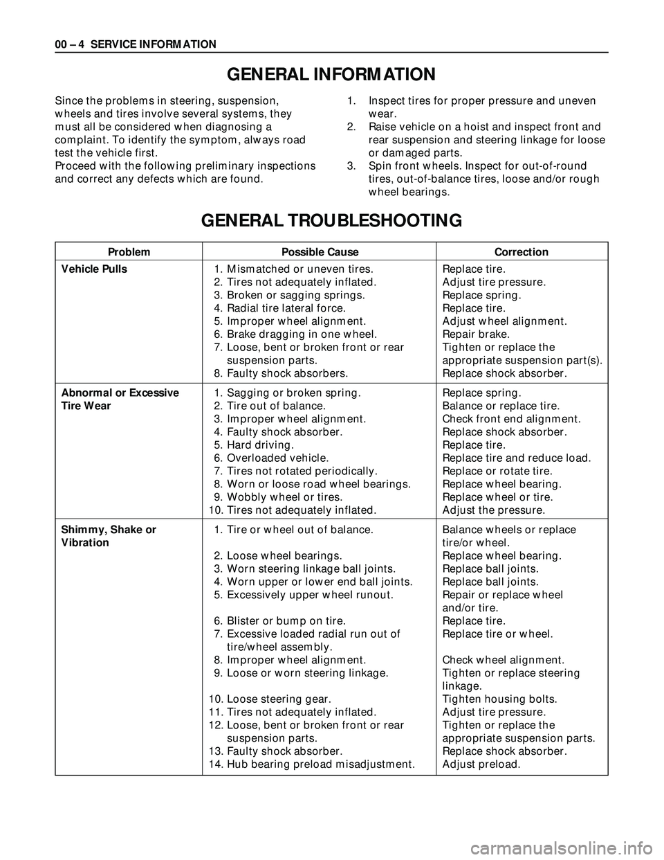
Problem Possible Cause Correction
00 – 4 SERVICE INFORMATION
GENERAL INFORMATION
Since the problems in steering, suspension,
wheels and tires involve several systems, they
must all be considered when diagnosing a
complaint. To identify the symptom, always road
test the vehicle first.
Proceed with the following preliminary inspections
and correct any defects which are found.1. Inspect tires for proper pressure and uneven
wear.
2. Raise vehicle on a hoist and inspect front and
rear suspension and steering linkage for loose
or damaged parts.
3. Spin front wheels. Inspect for out-of-round
tires, out-of-balance tires, loose and/or rough
wheel bearings.
GENERAL TROUBLESHOOTING
Vehicle Pulls
Abnormal or Excessive
Tire Wear
Shimmy, Shake or
Vibration1. Mismatched or uneven tires.
2. Tires not adequately inflated.
3. Broken or sagging springs.
4. Radial tire lateral force.
5. Improper wheel alignment.
6. Brake dragging in one wheel.
7. Loose, bent or broken front or rear
suspension parts.
8. Faulty shock absorbers.
1. Sagging or broken spring.
2. Tire out of balance.
3. Improper wheel alignment.
4. Faulty shock absorber.
5. Hard driving.
6. Overloaded vehicle.
7. Tires not rotated periodically.
8. Worn or loose road wheel bearings.
9. Wobbly wheel or tires.
10. Tires not adequately inflated.
1. Tire or wheel out of balance.
2. Loose wheel bearings.
3. Worn steering linkage ball joints.
4. Worn upper or lower end ball joints.
5. Excessively upper wheel runout.
6. Blister or bump on tire.
7. Excessive loaded radial run out of
tire/wheel assembly.
8. Improper wheel alignment.
9. Loose or worn steering linkage.
10. Loose steering gear.
11. Tires not adequately inflated.
12. Loose, bent or broken front or rear
suspension parts.
13. Faulty shock absorber.
14. Hub bearing preload misadjustment.Replace tire.
Adjust tire pressure.
Replace spring.
Replace tire.
Adjust wheel alignment.
Repair brake.
Tighten or replace the
appropriate suspension part(s).
Replace shock absorber.
Replace spring.
Balance or replace tire.
Check front end alignment.
Replace shock absorber.
Replace tire.
Replace tire and reduce load.
Replace or rotate tire.
Replace wheel bearing.
Replace wheel or tire.
Adjust the pressure.
Balance wheels or replace
tire/or wheel.
Replace wheel bearing.
Replace ball joints.
Replace ball joints.
Repair or replace wheel
and/or tire.
Replace tire.
Replace tire or wheel.
Check wheel alignment.
Tighten or replace steering
linkage.
Tighten housing bolts.
Adjust tire pressure.
Tighten or replace the
appropriate suspension parts.
Replace shock absorber.
Adjust preload.
Page 287 of 3573

SERVICE INFORMATION 00 – 5
Problem Possible Cause Correction
GENERAL TROUBLESHOOTING (CONT.)
Wheel Tramp or Hop
Hard Steering
Too Much Play In
Steering
Poor Steering Wheel
Returnability
Abnormal Noise1. Blister or bump on tire.
2. Improper shock absorber operation
1. Bind in steering linkage ball studs,
upper or lower end ball joint.
2. Improper wheel alignment.
3. Steering gear misadjustment.
4. Tire not adequately inflated.
5. Bind in steering column or shaft.
6. Improper power steering system
operation.
1. Wheel bearings worn.
2. Loose steering gear or linkage.
3. Steering gear misadjustment.
4. Worn or loose steering shaft universal
joint.
5. Worn steering linkage ball joints.
6. Worn upper or lower end ball joints.
1. Bind in steering linkage ball joints.
2. Bind in upper or lower end ball joints.
3. Bind in steering column and shaft.
4. Bind in steering gear.
5. Improper wheel alignment.
6. Tires not adequately inflated.
7. Loose steering wheel nut.
8. Worn wheel bearing.
1. Worn, sticky or loose upper or lower
end ball joint, steering linkage ball
joints or drive axle joints.
2. Faulty shock absorbers.
3. Worn upper or lower control arm bushing.
4. Loose stabilizer bar.
5. Loose wheel nuts.
6. Loose suspension bolts or nuts.
7. Broken or otherwise damaged wheel
bearings.
8. Broken suspension springs.
9. Loose steering gear.
10. Faulty steering gear.Replace tire.
Replace shock absorber.
Replace ball joints.
Check wheel alignment.
Check and adjust steering gear
preload.
Inflate tires to proper pressure.
Repair or replace.
Repair or replace.
Refer to "Power steering
system troubleshooting."
Replace wheel bearings.
Retighten or repair.
Inspect and adjust steering
gear preload.
Retighten or replace steering
shaft.
Replace ball joints.
Replace ball joints.
Replace ball joints.
Replace ball joints.
Repair or replace.
Check and repair steering gear.
Adjust wheel alignment.
Adjust tire pressure.
Retighten.
Replace.
Replace.
Replace or repair.
Replace.
Retighten bolts.
Tighten nuts. Check for
elongated wheel nut holes.
Replace wheel if required.
Retighten suspension bolts or
nuts.
Replace wheel bearing.
Replace spring.
Retighten mounting bolt.
Check and adjust steering gear.
Page 288 of 3573
00 – 6 SERVICE INFORMATION
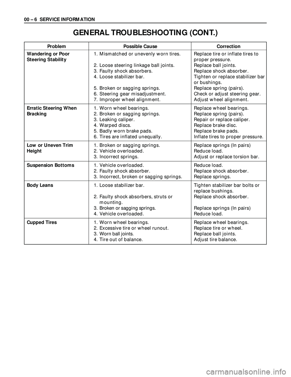
Problem Possible Cause Correction
GENERAL TROUBLESHOOTING (CONT.)
Wandering or Poor
Steering Stability
Erratic Steering When
Bracking
Low or Uneven Trim
Height
Suspension Bottoms
Body Leans
Cupped Tires1. Mismatched or unevenly worn tires.
2. Loose steering linkage ball joints.
3. Faulty shock absorbers.
4. Loose stabilizer bar.
5. Broken or sagging springs.
6. Steering gear misadjustment.
7. Improper wheel alignment.
1. Worn wheel bearings.
2. Broken or sagging springs.
3. Leaking caliper.
4. Warped discs.
5. Badly worn brake pads.
6. Tires are inflated unequally.
1. Broken or sagging springs.
2. Vehicle overloaded.
3. Incorrect springs.
1. Vehicle overloaded.
2. Faulty shock absorber.
3. Incorrect, broken or sagging springs.
1. Loose stabilizer bar.
2. Faulty shock absorbers, struts or
mounting.
3. Broken or sagging springs.
4. Vehicle overloaded.
1. Worn wheel bearings.
2. Excessive tire or wheel runout.
3. Worn ball joints.
4. Tire out of balance.Replace tire or inflate tires to
proper pressure.
Replace ball joints.
Replace shock absorber.
Tighten or replace stabilizer bar
or bushings.
Replace spring (pairs).
Check or adjust steering gear.
Adjust wheel alignment.
Replace wheel bearings.
Replace spring (pairs).
Repair or replace caliper.
Replace brake disc.
Replace brake pads.
Inflate tires to proper pressure.
Replace springs (In pairs)
Reduce load.
Adjust or replace torsion bar.
Reduce load.
Replace shock absorber.
Replace springs.
Tighten stabilizer bar bolts or
replace bushings.
Replace shock absorber.
Replace springs (In pairs)
Reduce load.
Replace wheel bearings.
Replace tire or wheel.
Replace ball joints.
Adjust tire balance.
Page 305 of 3573
INSPECTION
Before making any adjustments affecting caster, camber
or toe-in, the following front end inspection should be
made.
INSPECT
1. Tires for proper inflation pressure. Refer to “Wheels
and Tires” in section 3E.
2. Front wheel bearings for proper adjustment. Refer to
“Front Wheel Drive” in section 4C.
3. Ball joints, tie rod ends and relay rods. If excessive
looseness is noted, correct before adjusting. Refer to
“Steering Linkage” in section 2A.
4. Wheel and tires for run-out. Refer to “Wheels and
Tires”in section 3E.
5. Trim height. If not within specifications, the
correction must be made before adjusting caster.
6. Steering gear for looseness at the frame.
7. Shock absorbers for leaks or any noticeable noise.
Refer to “Front Suspension” in section 3C.
8. Control arms or stabilizer bar attachment for
looseness. Refer to “Front Suspension“ in section 3C.
9. Alignment equipment. Follow the manufacturer’s
instructions.
10. Level of the vehicle. The vehicle must be on a level
surface.
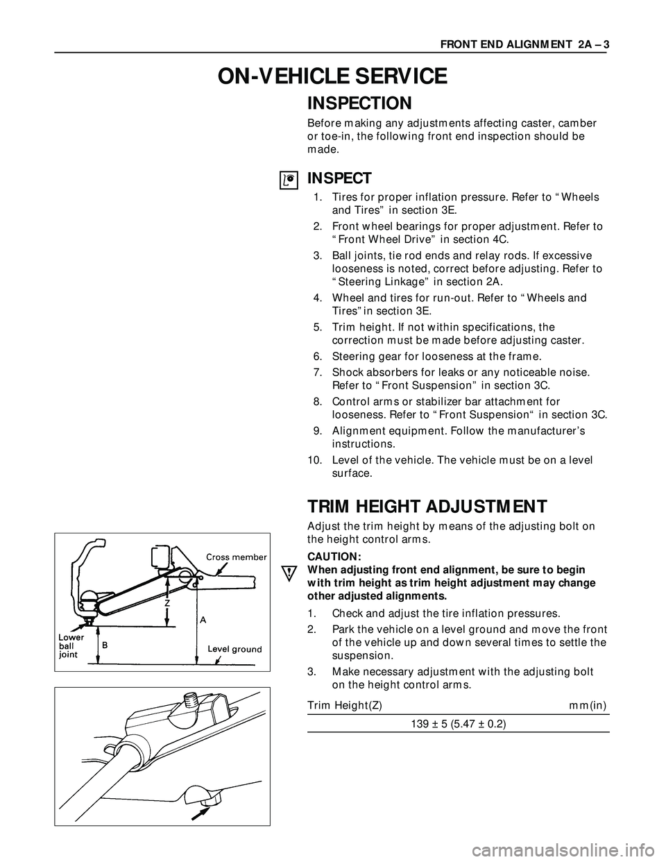
TRIM HEIGHT ADJUSTMENT
Adjust the trim height by means of the adjusting bolt on
the height control arms.
CAUTION:
When adjusting front end alignment, be sure to begin
with trim height as trim height adjustment may change
other adjusted alignments.
1. Check and adjust the tire inflation pressures.
2. Park the vehicle on a level ground and move the front
of the vehicle up and down several times to settle the
suspension.
3. Make necessary adjustment with the adjusting bolt
on the height control arms.
Trim Height(Z) mm(in)
139 ± 5 (5.47 ± 0.2)FRONT END ALIGNMENT 2A – 3
ON-VEHICLE SERVICE
Page 364 of 3573

2A Ð 62 SUPPLEMENTAL RESTRAINT SYSTEM STEERING WHEEL & COLUMN
Use special tool. Remove the steering wheel.
Move the tires to the straight ahead position before
removing the steering wheel.
Steering wheel remover: 5-8840-0016-0 (J-29752)
CAUTION:
Never apply force to the steering wheel in direction of the
shaft by using a hammer or other impact tools in an
attempt to remove the steering wheel. The steering shaft
is designed as an energy absorbing unit.
6. Steering Column Cover
7. Combination Switch and SRS Coil Assembly
1) Disconnect the wiring harness connectors
located under the steering column.
2) Remove the combination switch assembly with
SRS coil.
NOTE:
The SRS coil is a part of the combination switch
assembly, which can not be replaced separately.
Therefore, be sure not to remove the SRS coil from
the combination switch assembly.
825RS046
INSTALLATION
Alignment mark
7. Combination Switch and SRS Coil Assembly
1) After installation of combination switch
assembly, connect the combination switch
wiring harness connector and the SRS 2way
connector located under the steering column.
2) Turn the SRS coil counterclockwise to full, return
about 3 turns and align the neutral mark.
CAUTION:
When turning the SRS coil counterclockwise to full, stop
turning if resistance is felt. Forced further turning may
damage to the cable in the SRS coil.
826RW027
Starter switch
harness
Combination
switch harness
Inflator module
harness
Setting cowl
(Lower)
6. Steering Column Cover
When installing the steering column cover, be sure to
route each wire harness as illustrated so that the
harnesses do not catch on any moving parts.
825RS048
Page 373 of 3573
SUPPLEMENTAL RESTRAINT SYSTEM STEERING WHEEL & COLUMN 2A – 71
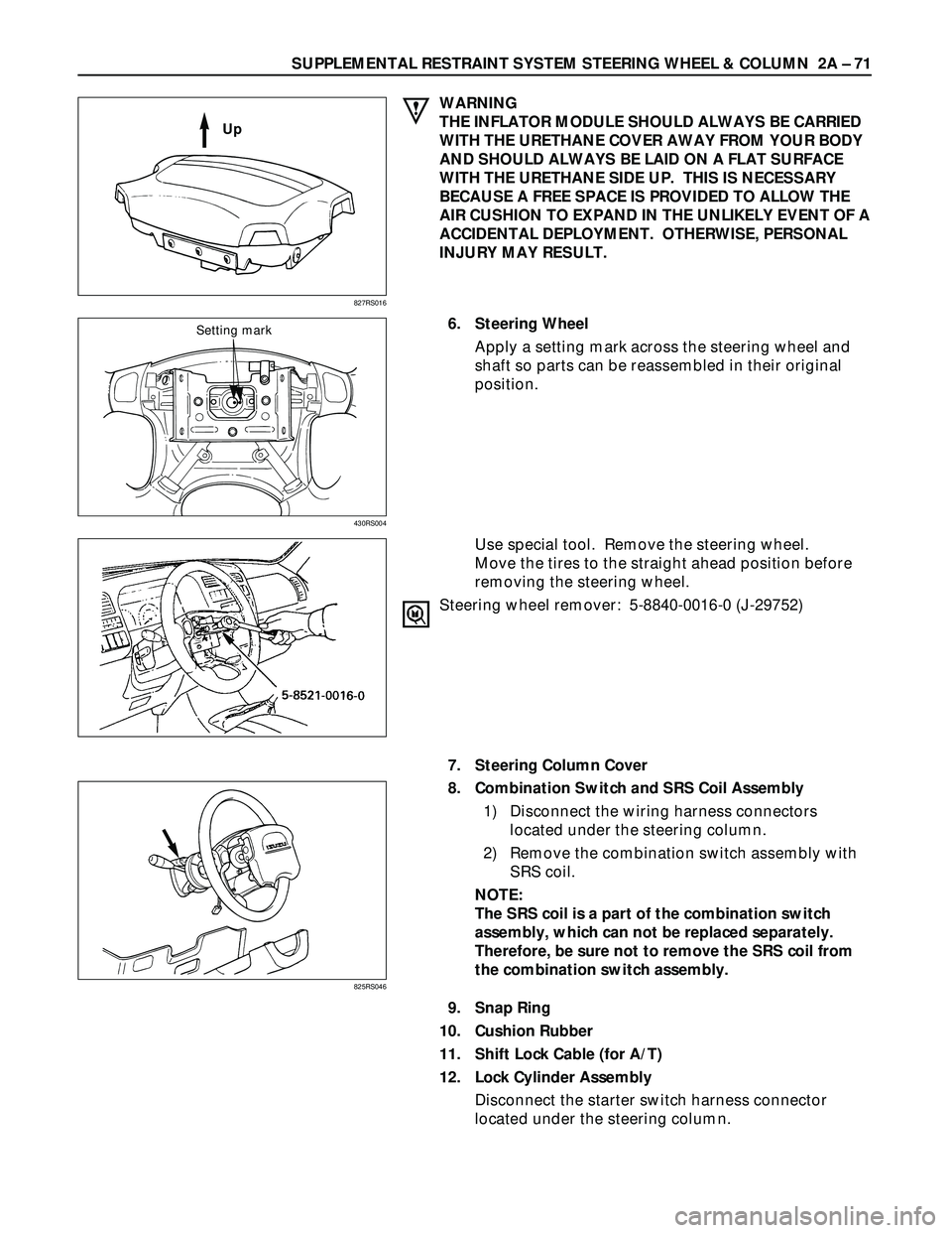
WARNING
THE INFLATOR MODULE SHOULD ALWAYS BE CARRIED
WITH THE URETHANE COVER AWAY FROM YOUR BODY
AND SHOULD ALWAYS BE LAID ON A FLAT SURFACE
WITH THE URETHANE SIDE UP. THIS IS NECESSARY
BECAUSE A FREE SPACE IS PROVIDED TO ALLOW THE
AIR CUSHION TO EXPAND IN THE UNLIKELY EVENT OF A
ACCIDENTAL DEPLOYMENT. OTHERWISE, PERSONAL
INJURY MAY RESULT.
6. Steering Wheel
Apply a setting mark across the steering wheel and
shaft so parts can be reassembled in their original
position.
Use special tool. Remove the steering wheel.
Move the tires to the straight ahead position before
removing the steering wheel.
Steering wheel remover: 5-8840-0016-0 (J-29752)
7. Steering Column Cover
8. Combination Switch and SRS Coil Assembly
1) Disconnect the wiring harness connectors
located under the steering column.
2) Remove the combination switch assembly with
SRS coil.
NOTE:
The SRS coil is a part of the combination switch
assembly, which can not be replaced separately.
Therefore, be sure not to remove the SRS coil from
the combination switch assembly.
9. Snap Ring
10. Cushion Rubber
11. Shift Lock Cable (for A/T)
12. Lock Cylinder Assembly
Disconnect the starter switch harness connector
located under the steering column.
827RS016
825RS046
Up
430RS004
Setting mark
Page 435 of 3573
3E – 4 WHEELS AND TIRES
TIRES
REPLACEMENT
When replacement is necessary, the original metric size
should be used. Most metric tire sizes do not have exact
corresponding alphanumeric tire sizes. It is recommended
that new tires be installed in pairs on the same axle. If
necessary to replace only one tire, it should be paired with
tire having the most tread, to equalize braking traction.
CAUTION:
Do not mix different types of tires such as radial, bias and
bias-belted tires except in emergencies, because vehicle
handling may be seriously affected and may result in loss
of control.
TIRE MOUNTING
Remove valve cap on valve stem and deflate the tire.
Then use a tire changing machine to mount or dismount
tires.
Follow the equipment manufacturer’s instruction. Do not
use hand tools or tire lever alone to change tires as they
may damage the tire beads or wheel rim.
TIRE DISMOUNTING
Rim bead seats should be cleaned with a wire brush or
coarse steel wool to remove lubricants, and light rust.
Before mounting a tire, the bead area should be well
lubricated with an approved tire lubricant.
After mounting, inflate the tire to 196 kPa (28 psi) so that
beads are completely seated. Inflate the air to specified
pressure and install valve cap to the stem
WARNING:
NEVER STAND OVER TIRE WHEN INFLATING. BEAD MAY
BREAK WHEN BEAD SNAPS OVER RIM’S SAFETY HUMP
AND CAUSE SERIOUS PERSONAL INJURY.
NEVER EXCEED 240 kPa (35 psi) PRESSURE WHEN
INFLATING. IF 240 kPa (35 psi) PRESSURE WILL NOT
SEAT BEADS, DEFLATE, RE-LUBRICATE AND RE-INFLATE.
OVER INFLATION MAY CAUSE THE BEAD TO BREAK AND
CAUSE SERIOUS PERSONAL INJURY.
TIRE REPAIR
There are many different materials on the market used to
repair tires.
Manufacturers have published detailed instructions on
how and when to repair tires. These instructions can be
obtained from the tire manufacturer if they are not
included with the repair kit.
UNIT REPAIR
Page 436 of 3573
WHEELS AND TIRES 3E – 5
WHEELS
REPLACEMENT
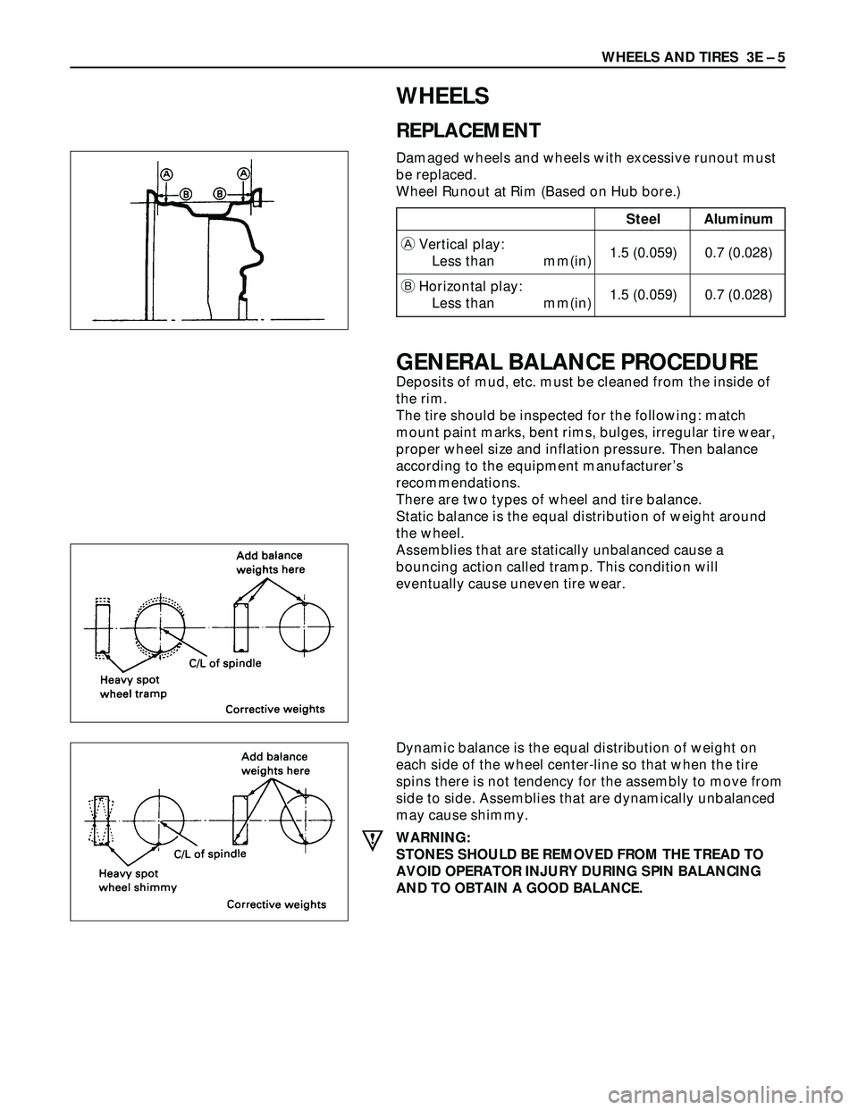
Damaged wheels and wheels with excessive runout must
be replaced.
Wheel Runout at Rim (Based on Hub bore.)
GENERAL BALANCE PROCEDURE
Deposits of mud, etc. must be cleaned from the inside of
the rim.
The tire should be inspected for the following: match
mount paint marks, bent rims, bulges, irregular tire wear,
proper wheel size and inflation pressure. Then balance
according to the equipment manufacturer’s
recommendations.
There are two types of wheel and tire balance.
Static balance is the equal distribution of weight around
the wheel.
Assemblies that are statically unbalanced cause a
bouncing action called tramp. This condition will
eventually cause uneven tire wear.
Dynamic balance is the equal distribution of weight on
each side of the wheel center-line so that when the tire
spins there is not tendency for the assembly to move from
side to side. Assemblies that are dynamically unbalanced
may cause shimmy.
WARNING:
STONES SHOULD BE REMOVED FROM THE TREAD TO
AVOID OPERATOR INJURY DURING SPIN BALANCING
AND TO OBTAIN A GOOD BALANCE.
Steel Aluminum
AVertical play:
Less than mm(in)1.5 (0.059) 0.7 (0.028)
BHorizontal play:
Less than mm(in)1.5 (0.059) 0.7 (0.028)