1998 ISUZU TROOPER front wheel bearing
[x] Cancel search: front wheel bearingPage 30 of 3573
MAINTENANCE AND LUBRICATION 0BÐ3
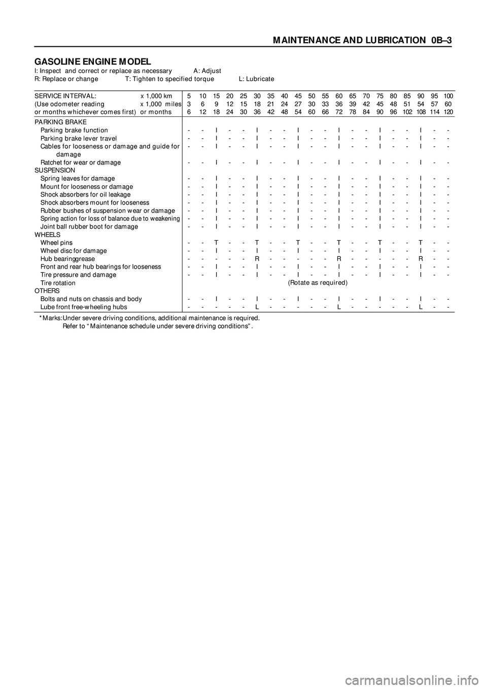
GASOLINE ENGINE MODELI: Inspect and correct or replace as necessary A: Adjust
R: Replace or change T: Tighten to specified torque L: Lubricate
SERVICE INTERVAL: x 1,000 km
(Use odometer reading x 1,000 miles
or months whichever comes first) or months5
3
610
6
1215
9
1820
12
2425
15
3030
18
3635
21
4240
24
4845
27
5450
30
6055
33
6660
36
7265
39
7870
42
8475
45
9080
48
9685
51
10290
54
10895
57
114100
60
120
PARKING BRAKE
Parking brake function
Parking brake lever travel
Cables for looseness or damage and guide for
damage
Ratchet for wear or damage
SUSPENSION
Spring leaves for damage
Mount for looseness or damage
Shock absorbers for oil leakage
Shock absorbers mount for looseness
Rubber bushes of suspension wear or damage
Spring action for loss of balance due to weakeningJoint ball rubber boot for damage
WHEELS
Wheel pins
Wheel disc for damage
Hub bearing grease
Front and rear hub bearings for looseness
Tire pressure and damage
Tire rotation
OTHERS
Bolts and nuts on chassis and body
Lube front free-wheeling hubs-
-
-
-
-
-
-
-
-
-
-
-
-
-
-
-
-
--
-
-
-
-
-
-
-
-
-
-
-
-
-
-
-
-
-I
I
I
I
I
I
I
I
I
I
I
T
I
-
I
I
I
--
-
-
-
-
-
-
-
-
-
-
-
-
-
-
-
-
--
-
-
-
-
-
-
-
-
-
-
-
-
-
-
-
-
-I
I
I
I
I
I
I
I
I
I
I
T
I
R
I
I
I
L-
-
-
-
-
-
-
-
-
-
-
-
-
-
-
-
-
--
-
-
-
-
-
-
-
-
-
-
-
-
-
-
-
-
-I
I
I
I
I
I
I
I
I
I
I
T
I
-
I
I
I
--
-
-
-
-
-
-
-
-
-
-
-
-
-
-
-
-
--
-
-
-
-
-
-
-
-
-
-
-
-
-
-
-
-
-I
I
I
I
I
I
I
I
I
I
I
T
I
R
I
I
I
L-
-
-
-
-
-
-
-
-
-
-
-
-
-
-
-
-
--
-
-
-
-
-
-
-
-
-
-
-
-
-
-
-
-
-I
I
I
I
I
I
I
I
I
I
I
T
I
-
I
I
I
--
-
-
-
-
-
-
-
-
-
-
-
-
-
-
-
-
--
-
-
-
-
-
-
-
-
-
-
-
-
-
-
-
-
-I
I
I
I
I
I
I
I
I
I
I
T
I
R
I
I
I
L-
-
-
-
-
-
-
-
-
-
-
-
-
-
-
-
-
--
-
-
-
-
-
-
-
-
-
-
-
-
-
-
-
-
-
(Rotate as required)
*Marks: Under severe driving conditions, additional maintenance is required.
Refer to “Maintenance schedule under severe driving conditions”.
Page 32 of 3573
MAINTENANCE AND LUBRICATION 0BÐ5
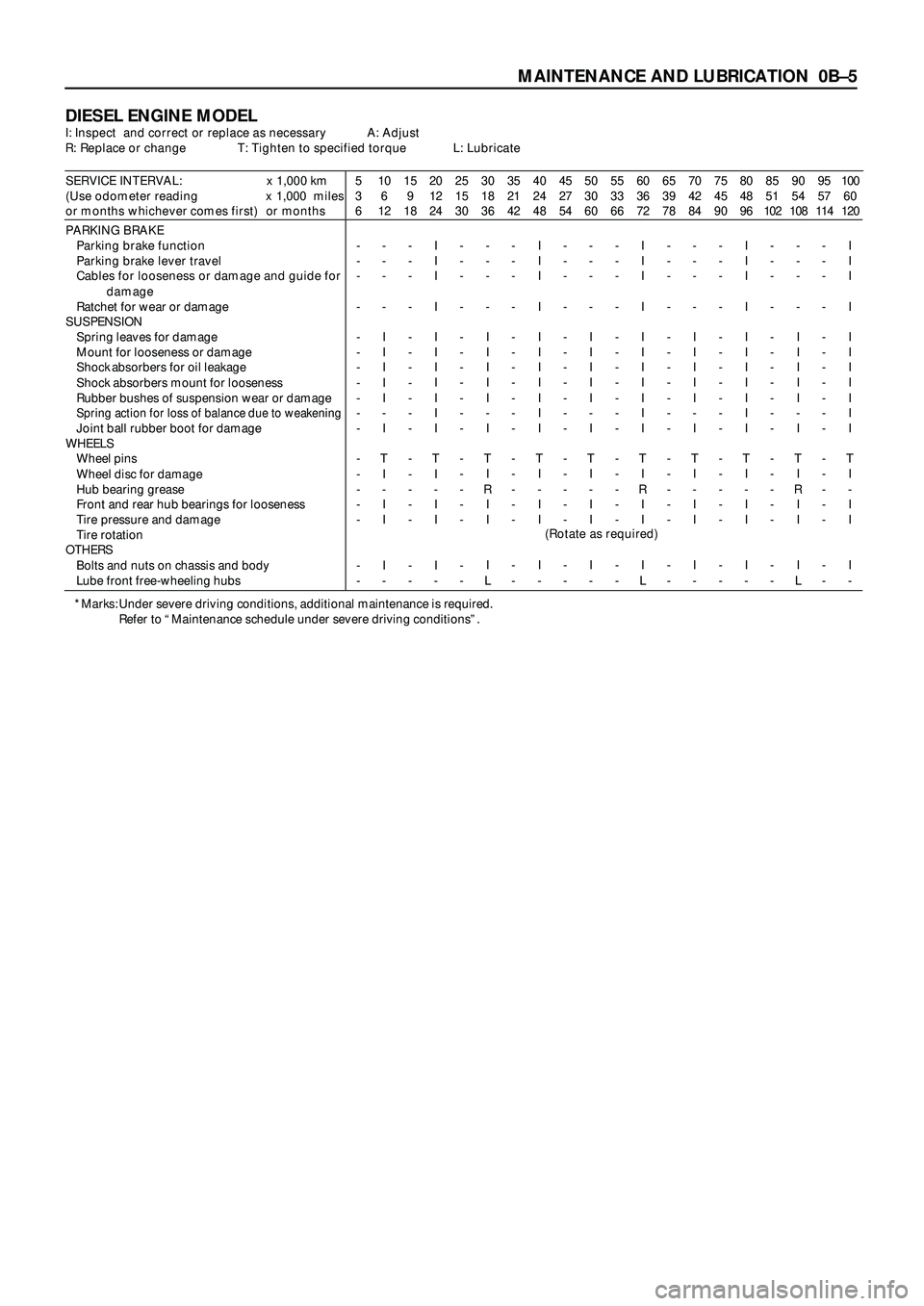
DIESEL ENGINE MODELI: Inspect and correct or replace as necessary A: Adjust
R: Replace or change T: Tighten to specified torque L: Lubricate
SERVICE INTERVAL: x 1,000 km
(Use odometer reading x 1,000 miles
or months whichever comes first) or months5
3
610
6
1215
9
1820
12
2425
15
3030
18
3635
21
4240
24
4845
27
5450
30
6055
33
6660
36
7265
39
7870
42
8475
45
9080
48
9685
51
10290
54
10895
57
114100
60
120
PARKING BRAKE
Parking brake function
Parking brake lever travel
Cables for looseness or damage and guide for
damage
Ratchet for wear or damage
SUSPENSION
Spring leaves for damage
Mount for looseness or damage
Shock absorbers for oil leakage
Shock absorbers mount for looseness
Rubber bushes of suspension wear or damage
Spring action for loss of balance due to weakeningJoint ball rubber boot for damage
WHEELS
Wheel pins
Wheel disc for damage
Hub bearing grease
Front and rear hub bearings for looseness
Tire pressure and damage
Tire rotation
OTHERS
Bolts and nuts on chassis and body
Lube front free-wheeling hubs-
-
-
-
-
-
-
-
-
-
-
-
-
-
-
-
-
--
-
-
-
I
I
I
I
I
-
I
T
I
-
I
I
I
--
-
-
-
-
-
-
-
-
-
-
-
-
-
-
-
-
-I
I
I
I
I
I
I
I
I
I
I
T
I
-
I
I
I
--
-
-
-
-
-
-
-
-
-
-
-
-
-
-
-
-
--
-
-
-
I
I
I
I
I
-
I
T
I
R
I
I
I
L-
-
-
-
-
-
-
-
-
-
-
-
-
-
-
-
-
-I
I
I
I
I
I
I
I
I
I
I
T
I
-
I
I
I
--
-
-
-
-
-
-
-
-
-
-
-
-
-
-
-
-
--
-
-
-
I
I
I
I
I
-
I
T
I
-
I
I
I
--
-
-
-
-
-
-
-
-
-
-
-
-
-
-
-
-
-I
I
I
I
I
I
I
I
I
I
I
T
I
R
I
I
I
L-
-
-
-
-
-
-
-
-
-
-
-
-
-
-
-
-
--
-
-
-
I
I
I
I
I
-
I
T
I
-
I
I
I
--
-
-
-
-
-
-
-
-
-
-
-
-
-
-
-
-
-I
I
I
I
I
I
I
I
I
I
I
T
I
-
I
I
I
--
-
-
-
-
-
-
-
-
-
-
-
-
-
-
-
-
--
-
-
-
I
I
I
I
I
-
I
T
I
R
I
I
I
L-
-
-
-
-
-
-
-
-
-
-
-
-
-
-
-
-
-I
I
I
I
I
I
I
I
I
I
I
T
I
-
I
I
I
-
(Rotate as required)
*Marks: Under severe driving conditions, additional maintenance is required.
Refer to “Maintenance schedule under severe driving conditions”.
Page 286 of 3573
Problem Possible Cause Correction
00 – 4 SERVICE INFORMATION
GENERAL INFORMATION
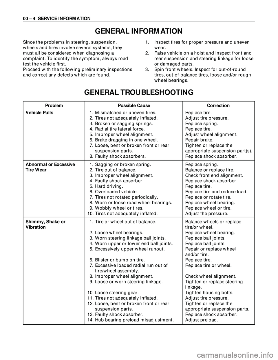
Since the problems in steering, suspension,
wheels and tires involve several systems, they
must all be considered when diagnosing a
complaint. To identify the symptom, always road
test the vehicle first.
Proceed with the following preliminary inspections
and correct any defects which are found.1. Inspect tires for proper pressure and uneven
wear.
2. Raise vehicle on a hoist and inspect front and
rear suspension and steering linkage for loose
or damaged parts.
3. Spin front wheels. Inspect for out-of-round
tires, out-of-balance tires, loose and/or rough
wheel bearings.
GENERAL TROUBLESHOOTING
Vehicle Pulls
Abnormal or Excessive
Tire Wear
Shimmy, Shake or
Vibration1. Mismatched or uneven tires.
2. Tires not adequately inflated.
3. Broken or sagging springs.
4. Radial tire lateral force.
5. Improper wheel alignment.
6. Brake dragging in one wheel.
7. Loose, bent or broken front or rear
suspension parts.
8. Faulty shock absorbers.
1. Sagging or broken spring.
2. Tire out of balance.
3. Improper wheel alignment.
4. Faulty shock absorber.
5. Hard driving.
6. Overloaded vehicle.
7. Tires not rotated periodically.
8. Worn or loose road wheel bearings.
9. Wobbly wheel or tires.
10. Tires not adequately inflated.
1. Tire or wheel out of balance.
2. Loose wheel bearings.
3. Worn steering linkage ball joints.
4. Worn upper or lower end ball joints.
5. Excessively upper wheel runout.
6. Blister or bump on tire.
7. Excessive loaded radial run out of
tire/wheel assembly.
8. Improper wheel alignment.
9. Loose or worn steering linkage.
10. Loose steering gear.
11. Tires not adequately inflated.
12. Loose, bent or broken front or rear
suspension parts.
13. Faulty shock absorber.
14. Hub bearing preload misadjustment.Replace tire.
Adjust tire pressure.
Replace spring.
Replace tire.
Adjust wheel alignment.
Repair brake.
Tighten or replace the
appropriate suspension part(s).
Replace shock absorber.
Replace spring.
Balance or replace tire.
Check front end alignment.
Replace shock absorber.
Replace tire.
Replace tire and reduce load.
Replace or rotate tire.
Replace wheel bearing.
Replace wheel or tire.
Adjust the pressure.
Balance wheels or replace
tire/or wheel.
Replace wheel bearing.
Replace ball joints.
Replace ball joints.
Repair or replace wheel
and/or tire.
Replace tire.
Replace tire or wheel.
Check wheel alignment.
Tighten or replace steering
linkage.
Tighten housing bolts.
Adjust tire pressure.
Tighten or replace the
appropriate suspension parts.
Replace shock absorber.
Adjust preload.
Page 289 of 3573
SERVICE INFORMATION 00 – 7
Problem Possible Cause Correction
POWER STEERING SYSTEM
HISSING NOISE
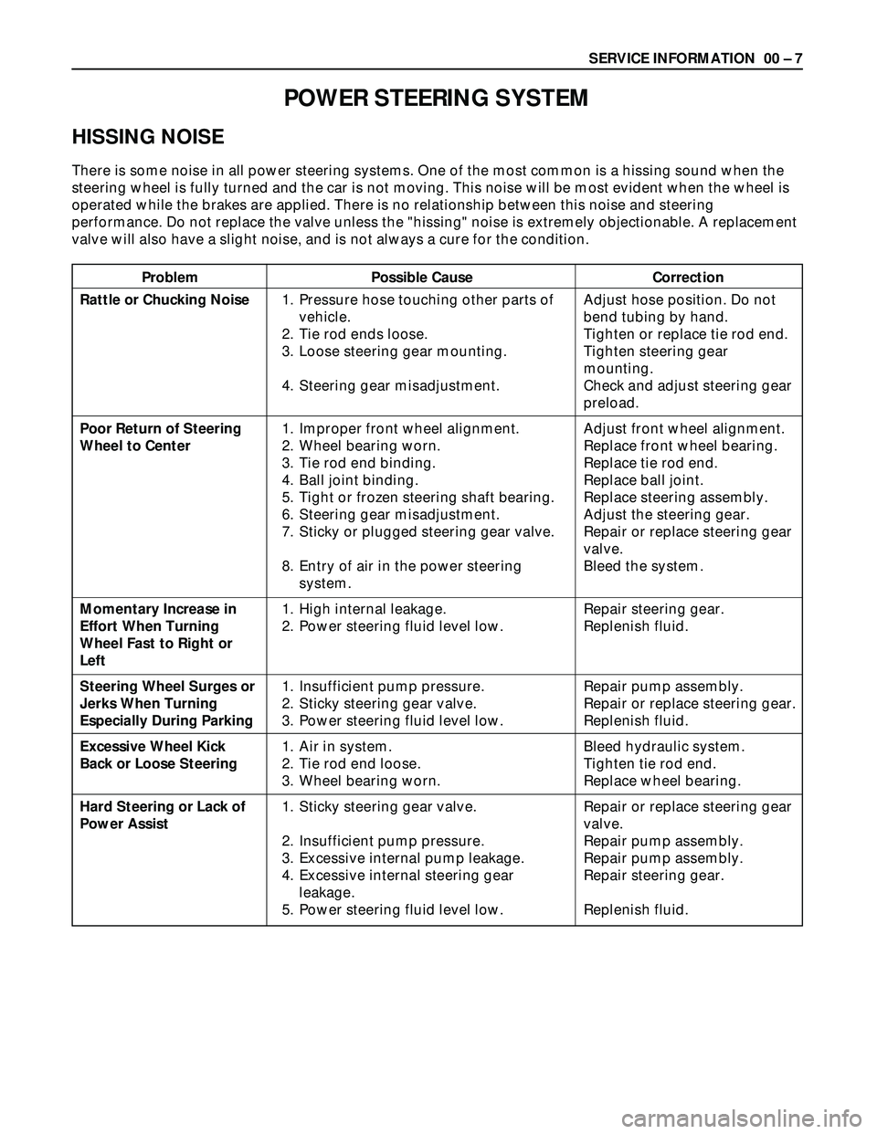
There is some noise in all power steering systems. One of the most common is a hissing sound when the
steering wheel is fully turned and the car is not moving. This noise will be most evident when the wheel is
operated while the brakes are applied. There is no relationship between this noise and steering
performance. Do not replace the valve unless the "hissing" noise is extremely objectionable. A replacement
valve will also have a slight noise, and is not always a cure for the condition.
Rattle or Chucking Noise
Poor Return of Steering
Wheel to Center
Momentary Increase in
Effort When Turning
Wheel Fast to Right or
Left
Steering Wheel Surges or
Jerks When Turning
Especially During Parking
Excessive Wheel Kick
Back or Loose Steering
Hard Steering or Lack of
Power Assist1. Pressure hose touching other parts of
vehicle.
2. Tie rod ends loose.
3. Loose steering gear mounting.
4. Steering gear misadjustment.
1. Improper front wheel alignment.
2. Wheel bearing worn.
3. Tie rod end binding.
4. Ball joint binding.
5. Tight or frozen steering shaft bearing.
6. Steering gear misadjustment.
7. Sticky or plugged steering gear valve.
8. Entry of air in the power steering
system.
1. High internal leakage.
2. Power steering fluid level low.
1. Insufficient pump pressure.
2. Sticky steering gear valve.
3. Power steering fluid level low.
1. Air in system.
2. Tie rod end loose.
3. Wheel bearing worn.
1. Sticky steering gear valve.
2. Insufficient pump pressure.
3. Excessive internal pump leakage.
4. Excessive internal steering gear
leakage.
5. Power steering fluid level low.Adjust hose position. Do not
bend tubing by hand.
Tighten or replace tie rod end.
Tighten steering gear
mounting.
Check and adjust steering gear
preload.
Adjust front wheel alignment.
Replace front wheel bearing.
Replace tie rod end.
Replace ball joint.
Replace steering assembly.
Adjust the steering gear.
Repair or replace steering gear
valve.
Bleed the system.
Repair steering gear.
Replenish fluid.
Repair pump assembly.
Repair or replace steering gear.
Replenish fluid.
Bleed hydraulic system.
Tighten tie rod end.
Replace wheel bearing.
Repair or replace steering gear
valve.
Repair pump assembly.
Repair pump assembly.
Repair steering gear.
Replenish fluid.
Page 305 of 3573
INSPECTION
Before making any adjustments affecting caster, camber
or toe-in, the following front end inspection should be
made.
INSPECT
1. Tires for proper inflation pressure. Refer to “Wheels
and Tires” in section 3E.
2. Front wheel bearings for proper adjustment. Refer to
“Front Wheel Drive” in section 4C.
3. Ball joints, tie rod ends and relay rods. If excessive
looseness is noted, correct before adjusting. Refer to
“Steering Linkage” in section 2A.
4. Wheel and tires for run-out. Refer to “Wheels and
Tires”in section 3E.
5. Trim height. If not within specifications, the
correction must be made before adjusting caster.
6. Steering gear for looseness at the frame.
7. Shock absorbers for leaks or any noticeable noise.
Refer to “Front Suspension” in section 3C.
8. Control arms or stabilizer bar attachment for
looseness. Refer to “Front Suspension“ in section 3C.
9. Alignment equipment. Follow the manufacturer’s
instructions.
10. Level of the vehicle. The vehicle must be on a level
surface.
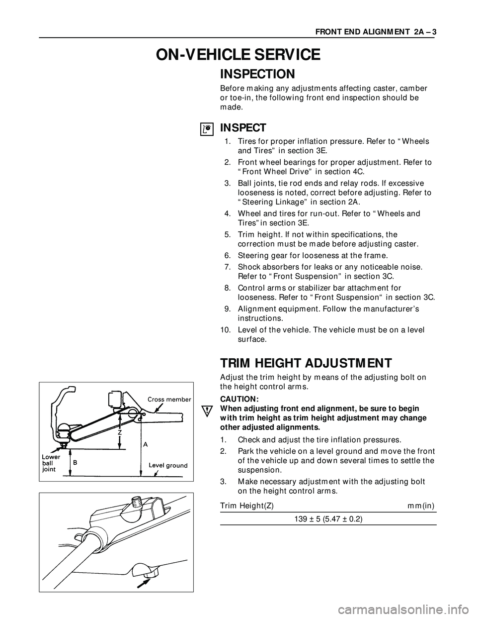
TRIM HEIGHT ADJUSTMENT
Adjust the trim height by means of the adjusting bolt on
the height control arms.
CAUTION:
When adjusting front end alignment, be sure to begin
with trim height as trim height adjustment may change
other adjusted alignments.
1. Check and adjust the tire inflation pressures.
2. Park the vehicle on a level ground and move the front
of the vehicle up and down several times to settle the
suspension.
3. Make necessary adjustment with the adjusting bolt
on the height control arms.
Trim Height(Z) mm(in)
139 ± 5 (5.47 ± 0.2)FRONT END ALIGNMENT 2A – 3
ON-VEHICLE SERVICE
Page 398 of 3573

3C – 10 FRONT SUSPENSION
KNUCKLE
Removal Steps
1. Torsion bar
2. Wheel speed sensor
(if equipped with ABS)
3. Back plate
4. Lower ball joint
5. Upper ball joint
6. Knuckle assembly
7. Oil seal
8. Thrust washer
9. Needle bearing
10. Knuckle
Installation Steps
10. Knuckle
9. Needle bearing
8. Thrust washer
7. Oil seal
6. Knuckle assembly
5. Upper ball joint
4. Lower ball joint
3. Back plate
2. Wheel speed sensor
(if equipped with ABS)
1. Torsion bar
Page 399 of 3573

FRONT SUSPENSION 3C – 11
REMOVAL
Preparation:
1) Raise the vehicle and support the frame with suitable
safety stands.
2) Remove wheel and tire assembly. Refer to “Wheels
and Tires” in section 3E.
3) Remove the brake caliper. Refer to “Brakes” in section
5.
4) Remove the hub assembly. Refer to “Hub and Disk” in
section 4C.
5) Remove outer track rod from the knuckle. Refer to
“Steering Linkage” in section 2A.
1. Torsion Bar
Loosen torsion bar by height control arm adjust bolt.
Refer to “Torsion bar” in this section.
2. Wheel speed sensor (if equipped with ABS)
3. Back Plate
4. Lower Ball Joint
Remover: 5-8840-2005-0 (J-29107)
CAUTION:
Be careful not to break the ball joint boot.
5. Upper Ball Joint
Remover: 5-8840-2121-0 (J-36831)
CAUTION:
Be careful not to break the ball joint boot.
6. Knuckle Assembly
7. Oil Seal
8. Washer
9. Needle Bearing
Remover: 5-8840-0019-0 (J-23907)
Page 439 of 3573
DIFFERENTIAL (FRONT) 4A1±2
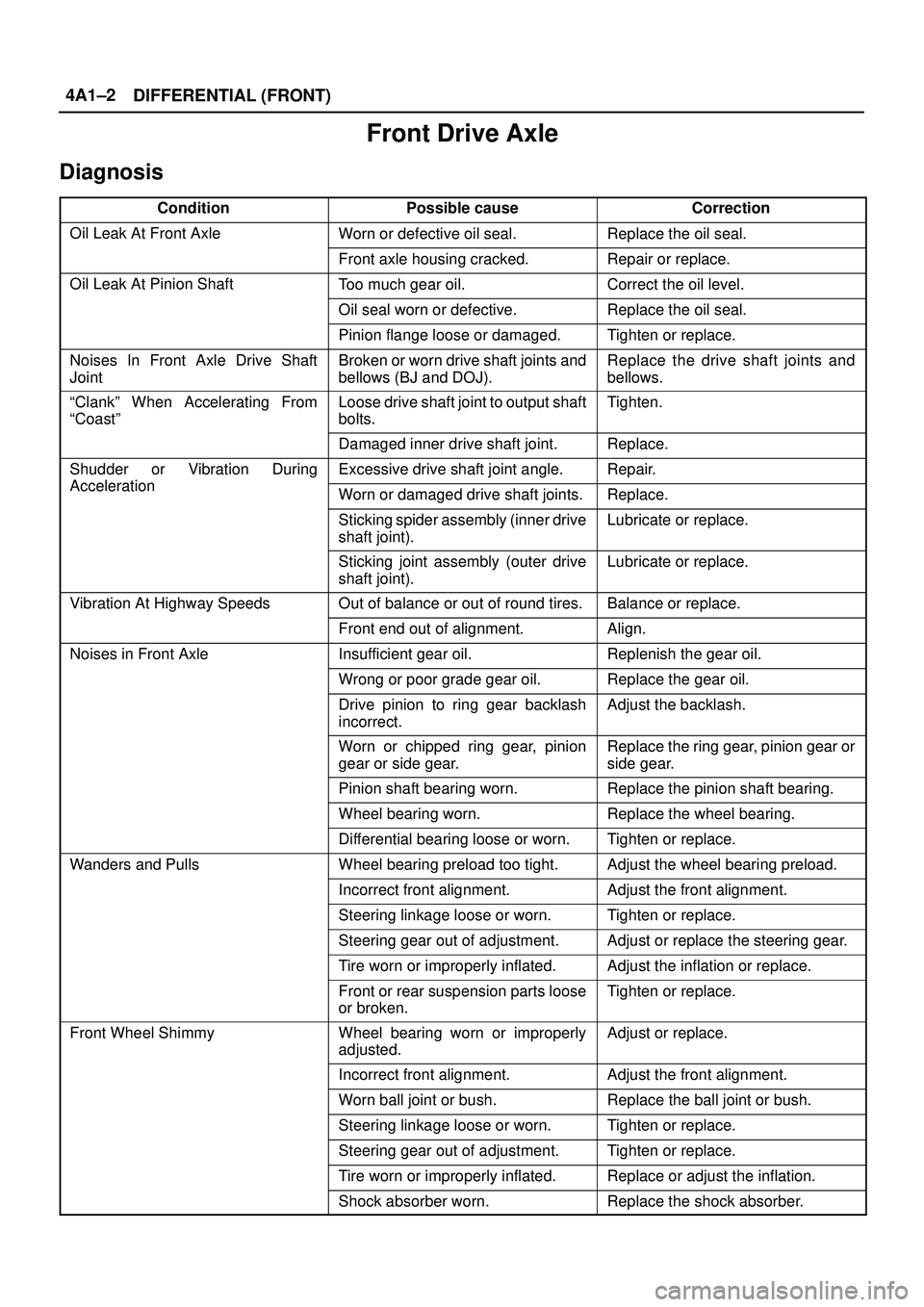
Front Drive Axle
Diagnosis
ConditionPossible causeCorrection
Oil Leak At Front AxleWorn or defective oil seal.Replace the oil seal.
Front axle housing cracked.Repair or replace.
Oil Leak At Pinion ShaftToo much gear oil.Correct the oil level.
Oil seal worn or defective.Replace the oil seal.
Pinion flange loose or damaged.Tighten or replace.
Noises In Front Axle Drive Shaft
JointBroken or worn drive shaft joints and
bellows (BJ and DOJ).Replace the drive shaft joints and
bellows.
ªClankº When Accelerating From
ªCoastºLoose drive shaft joint to output shaft
bolts.Tighten.
Damaged inner drive shaft joint.Replace.
Shudder or Vibration During
Acceleration
Excessive drive shaft joint angle.Repair.
AccelerationWorn or damaged drive shaft joints.Replace.
Sticking spider assembly (inner drive
shaft joint).Lubricate or replace.
Sticking joint assembly (outer drive
shaft joint).Lubricate or replace.
Vibration At Highway SpeedsOut of balance or out of round tires.Balance or replace.
Front end out of alignment.Align.
Noises in Front AxleInsufficient gear oil.Replenish the gear oil.
Wrong or poor grade gear oil.Replace the gear oil.
Drive pinion to ring gear backlash
incorrect.Adjust the backlash.
Worn or chipped ring gear, pinion
gear or side gear.Replace the ring gear, pinion gear or
side gear.
Pinion shaft bearing worn.Replace the pinion shaft bearing.
Wheel bearing worn.Replace the wheel bearing.
Differential bearing loose or worn.Tighten or replace.
Wanders and PullsWheel bearing preload too tight.Adjust the wheel bearing preload.
Incorrect front alignment.Adjust the front alignment.
Steering linkage loose or worn.Tighten or replace.
Steering gear out of adjustment.Adjust or replace the steering gear.
Tire worn or improperly inflated.Adjust the inflation or replace.
Front or rear suspension parts loose
or broken.Tighten or replace.
Front Wheel ShimmyWheel bearing worn or improperly
adjusted.Adjust or replace.
Incorrect front alignment.Adjust the front alignment.
Worn ball joint or bush.Replace the ball joint or bush.
Steering linkage loose or worn.Tighten or replace.
Steering gear out of adjustment.Tighten or replace.
Tire worn or improperly inflated.Replace or adjust the inflation.
Shock absorber worn.Replace the shock absorber.