Page 85 of 3573

00 Ð 46 SERVICE INFORMATION
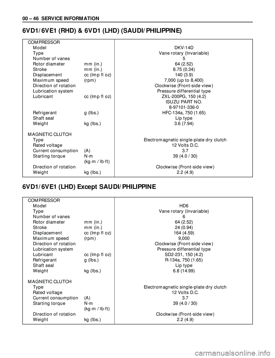
COMPRESSOR
Model DKV-14D
Type Vane rotary (Invariable)
Number of vanes 5
Rotor diameter mm (in.) 64 (2.52)
Stroke mm (in.) 8.75 (0.34)
Displacement cc (Imp fl oz) 140 (3.9)
Maximum speed (rpm) 7,000 (up to 8,400)
Direction of rotation Clockwise (Front-side view)
Lubrication system Pressure differential type
Lubricant cc (Imp fl oz) ZXL-200PG, 150 (4.2)
ISUZU PART NO.
8-97101-336-0
Refrigerant g (lbs.) HFC-134a, 750 (1.65)
Shaft seal Lip type
Weight kg (lbs.) 3.6 (7.94)
MAGNETIC CLUTCH
Type Electromagnetic single-plate dry clutch
Rated voltage 12 Volts D.C.
Current consumption (A) 3.7
Starting torque Nám 39 (4.0 / 30)
(kgám / lbáft)
Direction of rotation Clockwise (Front-side view)
Weight kg (lbs.) 2.2 (4.9)
6VD1/6VE1 (RHD) & 6VD1 (LHD) (SAUDI/PHILIPPINE)
6VD1/6VE1 (LHD) Except SAUDI/PHILIPPINE
COMPRESSOR
Model HD6
Type Vane rotary (Invariable)
Number of vanes 6
Rotor diameter mm (in.) 64 (2.52)
Stroke mm (in.) 24 (0.94)
Displacement cc (Imp fl oz) 164 (4.59)
Maximum speed (rpm) 9,000
Direction of rotation Clockwise (Front-side view)
Lubrication system Pressure differential type
Lubricant cc (Imp fl oz) SD2-231, 150 (4.2)
Refrigerant g (lbs.) R-134a, 750 (1.65)
Shaft seal Lip type
Weight kg (lbs.) 6.8 (14.99)
MAGNETIC CLUTCH
Type Electromagnetic single-plate dry clutch
Rated voltage 12 Volts D.C.
Current consumption (A) 3.7
Starting torque Nám 39 (4.0 / 30)
(kgám / lbáft)
Direction of rotation Clockwise (Front-side view)
Weight kg (lbs.) 2.2 (4.9)
Page 86 of 3573
SERVICE INFORMATION 00 Ð 47
4JG2/4JX1
COMPRESSOR
Model DKS-15CH
Type Swash plate type
Number of cylinder 6
Bore mm (in.) 36 (1.4)
Stroke mm (in.) 24 (0.94)
Displacement cc (Imp fl oz) 147 (4.1)
Maximum speed (rpm) 7,000 (up to 8,400)
Direction of rotation Clockwise (Front-side view)
Lubrication system Pressure differential type
Lubricant cc (Imp fl oz) ZXL-100PG, 150 (4.2)
ISUZU PART NO.
8-97101-338-0
Refrigerant g (lbs.) HFC-134a, 750 (1.65)
Shaft seal Lip type
Weight kg (lbs.) 4.1 (9.0)
MAGNETIC CLUTCH
Type Electromagnetic single-plate dry clutch
Rated voltage 12 Volts D.C.
Current consumption (A) 3.7
Starting torque Nám 49 (5.0 / 36)
(kgám / lbáft)
Direction of rotation Clockwise (Front-side view)
Weight kg (lbs.) 2.3 (5.1)
Page 122 of 3573
HEATING AND VENTILATION 1A Ð 27
Removal Steps
1. Control lever assembly
2. Bulb socket
3. Illumination bulb
Installation Steps
To install, follow the removal steps in the
reverse order.
CONTROL PANEL ILLUMINATION BULB
2 3 1
REMOVAL
Preparation:
Disconnect the battery ground cable
1. Control Lever Assembly
Refer to ÒCONTROL LEVER ASSEMBLYÓ removal
procedure in this section.
2. Bulb Socket
Pull out the socket from the panel by turning it
counterclockwise.
3. Illumination Bulb
Pull the illumination bulb from socket.
INSTALLATION
To install, follow the removal steps in the reverse order.
Page 145 of 3573

AIR CONDITIONING 1B Ð 19
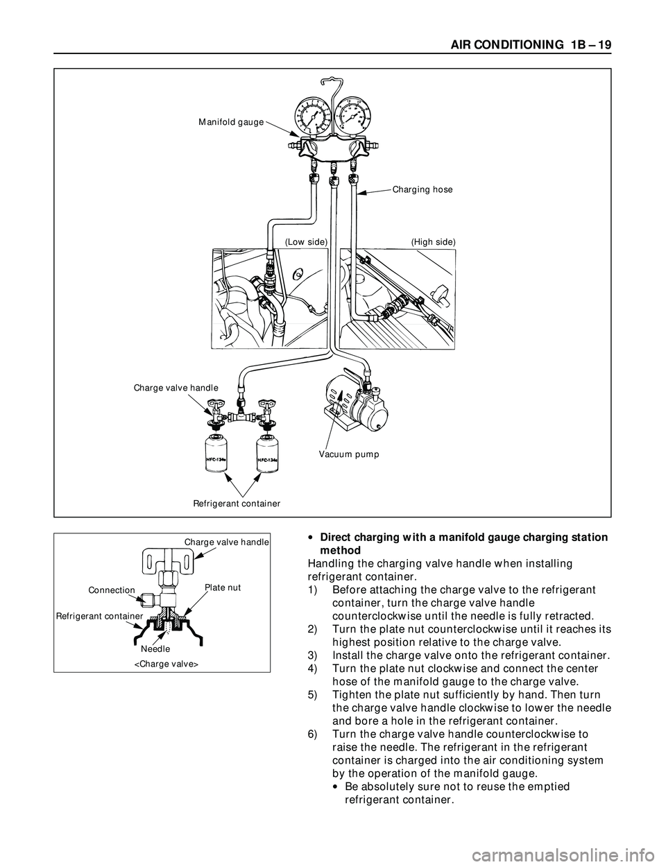
·Direct charging with a manifold gauge charging station
method
Handling the charging valve handle when installing
refrigerant container.
1) Before attaching the charge valve to the refrigerant
container, turn the charge valve handle
counterclockwise until the needle is fully retracted.
2) Turn the plate nut counterclockwise until it reaches its
highest position relative to the charge valve.
3) Install the charge valve onto the refrigerant container.
4) Turn the plate nut clockwise and connect the center
hose of the manifold gauge to the charge valve.
5) Tighten the plate nut sufficiently by hand. Then turn
the charge valve handle clockwise to lower the needle
and bore a hole in the refrigerant container.
6) Turn the charge valve handle counterclockwise to
raise the needle. The refrigerant in the refrigerant
container is charged into the air conditioning system
by the operation of the manifold gauge.
·Be absolutely sure not to reuse the emptied
refrigerant container.Charge valve handle
Plate nut
Needle Connection
Refrigerant container
Charging hose Manifold gauge
Vacuum pump
Refrigerant container
Charge valve handle
(Low side) (High side)
Page 146 of 3573

1B Ð 20 AIR CONDITIONING
1) Make sure the evacuation process is correctly
completed.
2) Connect the center-hose of the manifold gauge to the
refrigerant container.
·Turn the charge valve handle counterclockwise to
purge the charging line and purge any air existing
in the center-hose of the manifold gauge.
3) Open the low-pressure hand valve and charge the
refrigerant about 200 g(0.44 lbs.).
·Make sure the high-pressure hand valve is closed.
·Avoid charging the refrigerant by turning the
refrigerant container upside down.
4) Close the low-pressure hand valve of the manifold
gauge.
·Check to ensure that the degree of pressure does
not charge.
5) Check the refrigerant leaks by using a HFC-134a leak
detector.
·If a leak occurs, repair the leak connection, and
start all over again from the first step of
evacuation.
6) If no leaks are found, open the low-pressure hand
valve of the manifold gauge.Then continue charging
refrigerant to the system.
·When charging the system becomes difficult:
(1) Run the engine at Idling and close the all
vehicle doors.
(2) A/C switch is ÒONÓ.
(3) Set the fan control knob (fan switch) to its
highest position.
WARNING
BE ABSOLUTELY SURE NOT TO OPEN THE HIGH-
PRESSURE HAND VALVE. SHOULD THE HIGH-
PRESSURE HAND VALVE BE OPENED, THE HIGH-
PRESSURE REFRIGERANT GAS WOULD FLOW
BACKWARD, AND THIS MAY CAUSE THE
REFRIGERANT CONTAINER TO BURST.
7) When the refrigerant container is emptied, use the
following procedure to replace it with a new
refrigerant container.
(1) Close the low pressure hand valve.
(2) Raise the needle upward and remove the charge
valve.
(3) Reinstall the charge valve to the new refrigerant
container.
(4) Purge any air existing in the center hose of the
manifold gauge.
Page 174 of 3573
1B Ð 48 AIR CONDITIONING
1
2
3
Removal Steps
1. Control lever assembly
2. A/C switch
3. Illumination bulb
Installation Steps
To install, follow the removal steps in the
reverse order.
A/C SWITCH AND ILLUMINATION BULB
REMOVAL
Preparation:
Disconnect the battery ground cable
1. Control Lever Assembly
Refer to Section 1A ÒCONTROL LEVER ASSEMBLYÓ
removal procedure.
2. A/C Switch
Raise up the catch portion of the switch and remove
the switch while pushing it toward the outside.
3. Illumination Bulb
Turn the illumination bulb counterclockwise to
remove.
Catch portion
End of switch A/C switch
INSTALLATION
To install, follow the removal steps in the reverse order.
Page 188 of 3573
1BÐ62 AIR CONDITIONING
CIRCUIT DIAGRAM
6VE1 (RHD)
B-5
BLOWER
MOTOR2
B-5
1
I-51
3I-51
I-51I-51
MAX HI
RELAY POWER
TRANSISTORI-50
I-50
4
H-202
H-26
10
1
3
H-20
121 2L/B
0.5P/G
12
I-32
16 I-32
P-2
0.85W/G5W
5W 0.5R/W
0.3B0.5R/W 0.3R/W
TAIL RELAY(4) ILLUMINATION
CONTROLLER0.5G/R 0.85G/R
1.25B
1.25B1.25B
0.5B
9 I-32 5W 3W
BATT
FL-1
80A
MAIN4B-36
33L/R
C-19 25A
BLOWERC-20 10A
AIR CON
3L 2L/B
0.3BR
0.5BR0.3BR 2/B 0.3GR
0.3GR/L0.5L/B
2/B
B-36
20
H-27 2
B-36H-14
1
B-36HEATER & A/C RELAY
STARTER RELAY(1)
H-141
H-1310
I-328
H-269
10 C-16
10A CLOCK ROOM
BODY-RHBODY-LH
B-18
B-19
B-1
AUTO A/C CONTROL UNITAUTO A/C CONTROL UNIT
I-3217
14 35 2112 337
I-32
22
29 6I-331 H-20
14
H-16
M
192B
I-33
2I-50
D08RY00118
Page 192 of 3573
1BÐ66 AIR CONDITIONING
6VE1 (LHD)
0.5R/G
ILLUMINATION
CONTROLLER
12
I-32
157
I-32
16 I-3229
P-2
0.85W/R5W
3L 2L/B 2L/BBATT.
5W 0.5R/W
0.3B0.5R/W 0.3R/W
TAIL REAY(4) 0.5G/R 0.85R/W
1.25B
1.25B
0.5B
9 I-3236 5W 3W FL-1
80A
MAIN4
B-36
33L/RC-20 10A
AIR CON
C-19 25A
BLOWER
BLOWER
MOTOR
B-36 2
B-36H-14
1
B-36HEATER A/C RELAY
STARTER SW (ACC)
H-141
I-328
H-265
10 C-16 10A
CLOCK ROOM
C-11 10A
AUDIO
F-12 10A
TAIL-RH
BODY-LHB-19
BODY-RHB-22BH-481.25B 15
H-2614
I-50 2
AUTO A/C CONTORL UNIT AUTO A/C CONTORL UNIT
I-32
6
H-16
0.5BR 2B 2B0.3GR/W0.5L/B
0.3BR 0.3BR
19
I-33
33
22 21 3512
H-48
0.3GR/L
MAX HI
RELAY POWER
TRANSISTOR
I-51
3
H-4811
I-51
4I-50
3
I-512I-501
H-4815
I-511
B-51
B-5
2
H-484
M
17
I-33
14
D08RY00121