Page 325 of 3573
POWER STEERING 2A – 23
DISASSEMBLY
CAUTION:
Do not clamp the steering gear assembly in a vise by the
power cylinder housing.
1. Dust Cover
2. Retaining Ring
3. Back up RIng
4. Oil Seal
1) Clean the faces of the extended stub shaft.
2) Plug the hose fitting on the inlet side.
3) Remove the oil seal by blowing compressed air
through the hole in the outlet side.
5. Lock Nut
Remove the adjusting screw lock nut and turn the
adjusting screw counterclockwise to remove the
preload between the sector gear and the rack piston,
then remove the top cover bolts.
6. Top Cover Assembly
Holding the top cover stationary, turn the adjusting
screw clockwise to raise and free to cover, then
remove the cover.
7. O-ring
8. Sector Shaft
Bring the stub shaft into straight-ahead position. Do
not force the sector shaft off the gear box with a
hammer or other impact tools.
Page 348 of 3573
2A – 46 STEERING LINKAGE
OUTER TRACK ROD ASSEMBLY
Removal Steps
1. Nut and cotter pin, center track rod
2. Nut and cotter pin, knuckle arm
3. Lock nut, outer
4. Rod end assembly outer
5. Lock nut, inner
6. Rod end assembly, inner
�The screw is threaded
counterclockwise.
Installation Steps
6. Rod end assembly, inner
5. Lock nut, inner
4. Rod end assembly outer
3. Lock nut, outer
2. Nut and cotter pin, knuckle arm
1. Nut and cotter pin, center track
rod These steps are based on the LHD model.
Page 349 of 3573
STEERING LINKAGE 2A – 47
REMOVAL
Preparation:
Remove wheel and tire assembly.
Refer to “Wheels and Tires” in section 3E.
1. Nut and Cotter Pin, Center Track Rod
Disconnect outer track rod assembly at the center
track rod.
Remover: 5-8840-2121-0 (J-36831)
CAUTION:
Be careful not to break the ball joint boot.
2. Nut and Cotter Pin, Knuckle Arm
Remove outer track rod assembly from the knuckle
arm.
Remover: 5-8840-2121-0 (J-36831)
CAUTION:
Be careful not to break the ball joint boot.
3. Lock Nut, Outer
NOTE:
In either outer rod, the screw on the right side of the
vehicle is threaded counterclockwise.
6. Rod End, Inner
Apply setting marks to ensure reassembly of the
parts in their original position.
4. Rod End Assembly, Outer
Apply setting marks to ensure reassembly of the
parts in their original position.
5. Lock Nut, Inner
NOTE:
In either outer rod, the screw on the right side of the
vehicle is threaded counterclockwise.
Page 350 of 3573

2A – 48 STEERING LINKAGE
INSPECTION AND REPAIR
Make necessary correction or parts replacement if wear,
damage, corrosion, bending, deteriorations or any other
abnormal condition are found through inspection.
Check the following parts.
•Rod end assembly
•Ball joint (Boot, screws and tapered surfaces)
INSTALLATION
6. Rod End, Inner
Align the setting marks applied during desassembly.
5. Lock Nut, Inner
Lock Nut Torque N·m (kg·m/lb·ft)
118 (12.0 / 87)
NOTE:
In either outer rod, the screw on the right side of the
vehicle is threaded counterclockwise.
4. Rod End Assembly, Outer
Align the setting marks applied during disassembly.
3 Lock Nut, Outer
Lock Nut Torque N·m (kg·m/lb·ft)
118 (12.0 / 87)
2. Nut and Cotter pin, Knuckle Arm
Tighten the nut to the specified torque, with just
enough additional torque to align cotter pin holes.
Install new cotter pin.
Knuckle Arm Nut Torque N·m (kg·m/lb·ft)
98 (10.0 / 72)
1. Nut and Cotter Pin, Center Track Rod
Tighten the nut to the specified torque, with just
enough additional torque to align cotter pin holes.
Install new cotter pin.
Track Rod Nut Torque N·m (kg·m/lb·ft)
98 (10.0 / 72)
NOTE:
If replacing the track rod, adjust the new track rod
length.
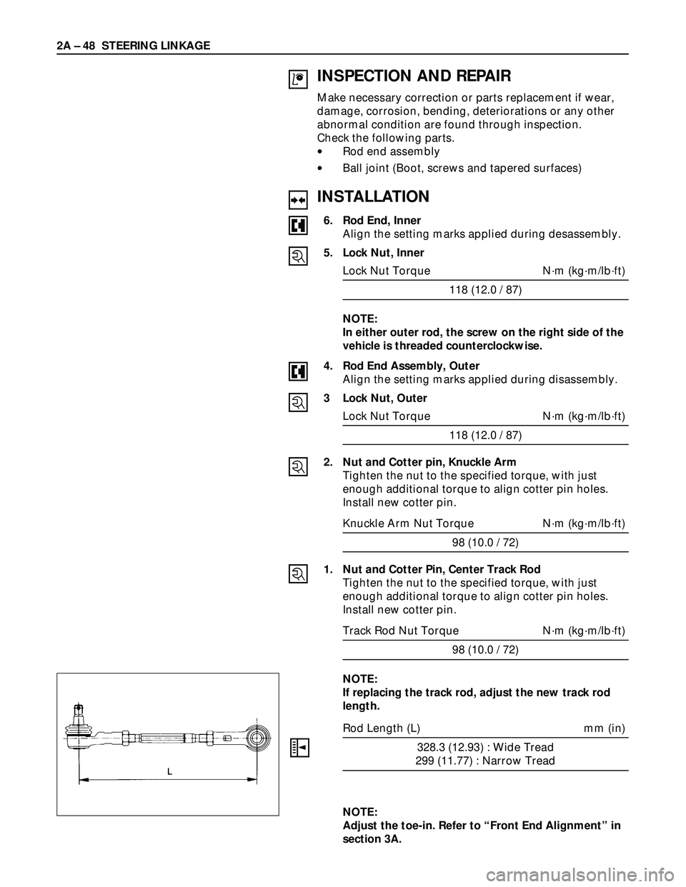
Rod Length (L) mm (in)
328.3 (12.93) : Wide Tread
299 (11.77) : Narrow Tread
NOTE:
Adjust the toe-in. Refer to “Front End Alignment” in
section 3A.
Page 364 of 3573

2A Ð 62 SUPPLEMENTAL RESTRAINT SYSTEM STEERING WHEEL & COLUMN
Use special tool. Remove the steering wheel.
Move the tires to the straight ahead position before
removing the steering wheel.
Steering wheel remover: 5-8840-0016-0 (J-29752)
CAUTION:
Never apply force to the steering wheel in direction of the
shaft by using a hammer or other impact tools in an
attempt to remove the steering wheel. The steering shaft
is designed as an energy absorbing unit.
6. Steering Column Cover
7. Combination Switch and SRS Coil Assembly
1) Disconnect the wiring harness connectors
located under the steering column.
2) Remove the combination switch assembly with
SRS coil.
NOTE:
The SRS coil is a part of the combination switch
assembly, which can not be replaced separately.
Therefore, be sure not to remove the SRS coil from
the combination switch assembly.
825RS046
INSTALLATION
Alignment mark
7. Combination Switch and SRS Coil Assembly
1) After installation of combination switch
assembly, connect the combination switch
wiring harness connector and the SRS 2way
connector located under the steering column.
2) Turn the SRS coil counterclockwise to full, return
about 3 turns and align the neutral mark.
CAUTION:
When turning the SRS coil counterclockwise to full, stop
turning if resistance is felt. Forced further turning may
damage to the cable in the SRS coil.
826RW027
Starter switch
harness
Combination
switch harness
Inflator module
harness
Setting cowl
(Lower)
6. Steering Column Cover
When installing the steering column cover, be sure to
route each wire harness as illustrated so that the
harnesses do not catch on any moving parts.
825RS048
Page 369 of 3573

SUPPLEMENTAL RESTRAINT SYSTEM STEERING WHEEL & COLUMN 2A – 67
INSTALLATION
11. Lock Cylinder Assembly
10. Shift Lock Cable (for A/T)
9. Cushion rubber
8. Snap ring
7. Combination Switch and SRS Coil Assembly
1) After installation of combination switch
assembly, connect the combination switch
wiring harness connector and the SRS 2way
connector located under the steering column.
2) Turn the SRS coil counterclockwise to full, return
about 3 turns and align the neutral mark.
CAUTION:
When turning the SRS coil counterclockwise to full, stop
turning if resistance is felt. Forced further turning may
damage to the cable in the SRS coil.
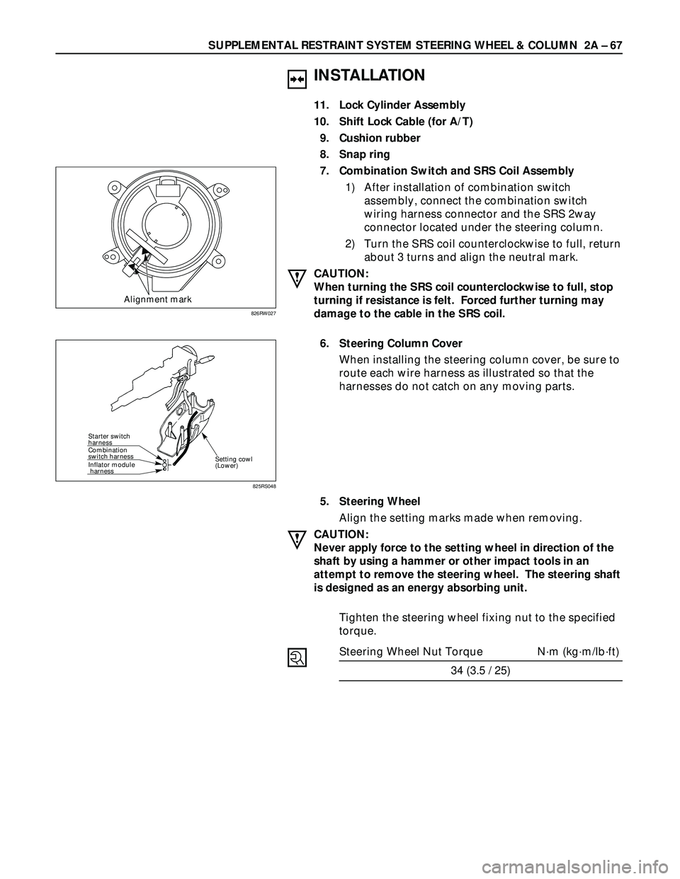
6. Steering Column Cover
When installing the steering column cover, be sure to
route each wire harness as illustrated so that the
harnesses do not catch on any moving parts.
5. Steering Wheel
Align the setting marks made when removing.
CAUTION:
Never apply force to the setting wheel in direction of the
shaft by using a hammer or other impact tools in an
attempt to remove the steering wheel. The steering shaft
is designed as an energy absorbing unit.
Tighten the steering wheel fixing nut to the specified
torque.
Steering Wheel Nut Torque N·m (kg·m/lb·ft)
34 (3.5 / 25)
Alignment mark
826RW027
Starter switch
harness
Combination
switch harness
Inflator module
harness
Setting cowl
(Lower)
825RS048
Page 374 of 3573

2A – 72 SUPPLEMENTAL RESTRAINT SYSTEM STEERING WHEEL & COLUMN
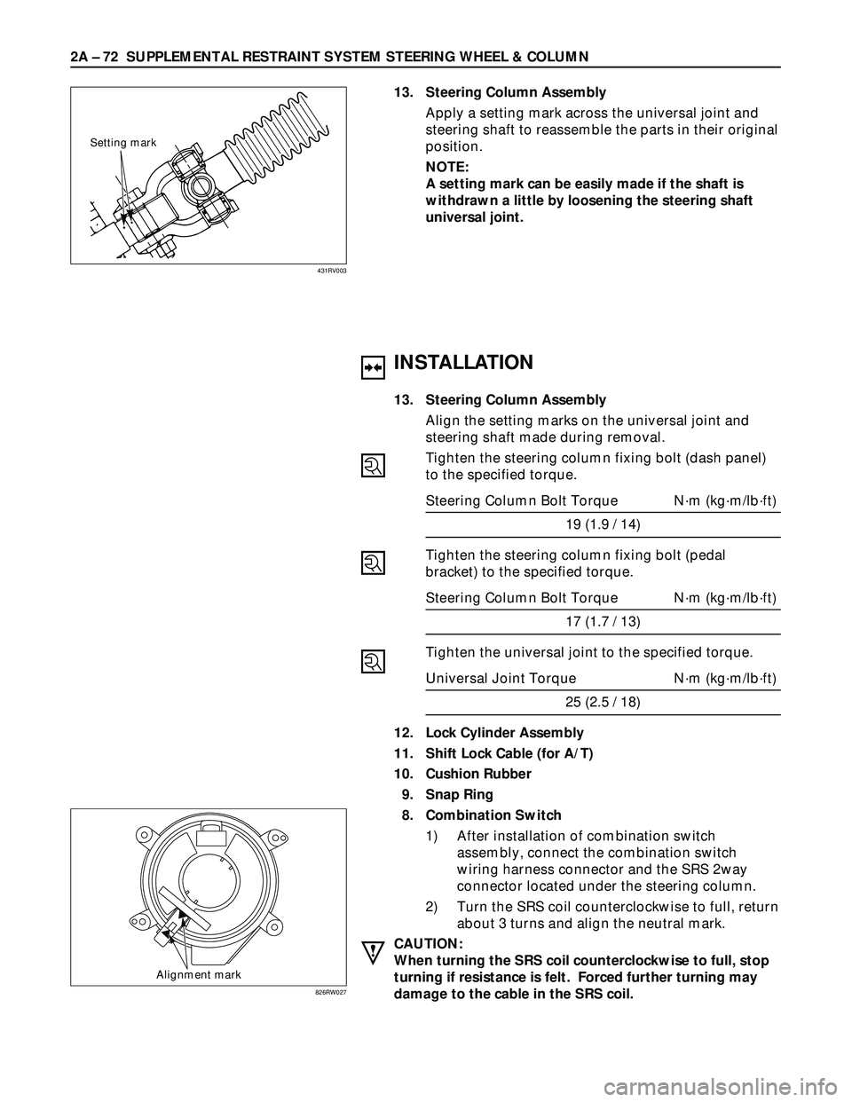
Setting mark
13. Steering Column Assembly
Apply a setting mark across the universal joint and
steering shaft to reassemble the parts in their original
position.
NOTE:
A setting mark can be easily made if the shaft is
withdrawn a little by loosening the steering shaft
universal joint.
431RV003
INSTALLATION
13. Steering Column Assembly
Align the setting marks on the universal joint and
steering shaft made during removal.
Tighten the steering column fixing bolt (dash panel)
to the specified torque.
Steering Column Bolt Torque N·m (kg·m/lb·ft)
19 (1.9 / 14)
Tighten the steering column fixing bolt (pedal
bracket) to the specified torque.
Steering Column Bolt Torque N·m (kg·m/lb·ft)
17 (1.7 / 13)
Tighten the universal joint to the specified torque.
Universal Joint Torque N·m (kg·m/lb·ft)
25 (2.5 / 18)
12. Lock Cylinder Assembly
11. Shift Lock Cable (for A/T)
10. Cushion Rubber
9. Snap Ring
8. Combination Switch
1) After installation of combination switch
assembly, connect the combination switch
wiring harness connector and the SRS 2way
connector located under the steering column.
2) Turn the SRS coil counterclockwise to full, return
about 3 turns and align the neutral mark.
CAUTION:
When turning the SRS coil counterclockwise to full, stop
turning if resistance is felt. Forced further turning may
damage to the cable in the SRS coil.
Alignment mark
826RW027
Page 450 of 3573

4A1±13 DIFFERENTIAL (FRONT)
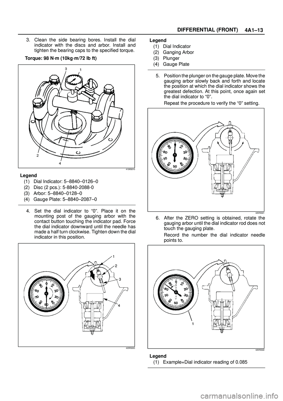
3. Clean the side bearing bores. Install the dial
indicator with the discs and arbor. Install and
tighten the bearing caps to the specified torque.
Torque: 98 N´m (10kg´m/72 lb ft)
415RS010
Legend
(1) Dial Indicator: 5±8840±0126±0
(2) Disc (2 pcs.): 5-8840-2088-0
(3) Arbor: 5±8840±0128±0
(4) Gauge Plate: 5±8840±2087±0
4. Set the dial indicator to ª0º. Place it on the
mounting post of the gauging arbor with the
contact button touching the indicator pad. Force
the dial indicator downward until the needle has
made a half turn clockwise. Tighten down the dial
indicator in this position.
425RS020
Legend
(1) Dial Indicator
(2) Ganging Arbor
(3) Plunger
(4) Gauge Plate
5. Position the plunger on the gauge plate. Move the
gauging arbor slowly back and forth and locate
the position at which the dial indicator shows the
greatest defection. At this point, once again set
the dial indicator to ª0º.
Repeat the procedure to verify the ª0º setting.
425RS021
6. After the ZERO setting is obtained, rotate the
gauging arbor until the dial indicator rod does not
touch the gauging plate.
Record the number the dial indicator needle
points to.
425RS022
Legend
(1) Example=Dial indicator reading of 0.085