Page 1106 of 3573
6D3±15 STARTING AND CHARGING SYSTEM
Main Data and Specifications
General Specifications
ModelHITACHI GD002350
Rating
Voltage12 V
Output1.4 Kw
Time30 sec
Number of teeth of pinion 9
Rotating direction(as viewed from pinion)Clockwise
Weight(approx.)34 N
No load characteristics
Voltage /Current 11V/90A or less
Speed 2700rpm or more
Load characteristics
Voltage/current 8.4V/250A
Torque 7.3N´m(64lb´in.) or more
Speed 1200rpm or more
Locking characteristics
Voltage/current 3V/750A or less
Torque19N´m(14lb´in) or more
Page 1117 of 3573
6D3±26STARTING AND CHARGING SYSTEM
Main Data and Specifications
General Specifications
Parts Number (Nippon denso)102211Ð5030
ModelACHD04
Rated voltage12 V
Rated output75 A
Rotating direction (As viewed from pulley)Clockwise
Pulley effective diameter50 mm (1.97 in)
Weight44 N (33 lb)
Page 1375 of 3573
6E±258
ENGINE DRIVEABILITY AND EMISSIONS
Diagnostic Trouble Code (DTC) P1625 PCM Unexpected Reset
Circuit Description
The powertrain control module (PCM) monitors
unexpected PCM reset. This will not turn on MIL light on,
only records code DTC P1625.
Conditions for Setting the DTC
�Clock or COP reset.
Action Taken When the DTC Sets
�The PCM will not illuminate the malfunction indicator
lamp (MIL).
�The PCM will store conditions which were present
when the DTC was set as Failure Records only. This
information will not be stored as Freeze Frame data.
Conditions for Clearing the MIL/DTC
�DTC P1625 can be cleared by using the Tech 2 ªClear
Infoº function or by disconnecting the PCM battery
feed.
Diagnostic Aids
Check for the following conditions:
�P1625 alone stored does not need diagnosis. Clear
DTC code.
Page 1427 of 3573

6E±310
ENGINE DRIVEABILITY AND EMISSIONS
Pedal Stroke Adjustment Procedure
1. Loosen the jam nut and rotate the kick-down switch
counterclockwise.
TS24039
2. Fully depress the pedal and hold it by hand. Rotate
the switch clockwise until the switch clicks.
3. Rotate the switch 1/2 turn further and lock it in this
position by tightening the jam nut.
TS24040
4. Step on the accelerator pedal and make sure there is
a clicking sound at the full-stroke position.
Fuel Filter Cap
General Description
The fuel filler cap includes a vacuum valve and a pressure
valve.If high vacuum or high pressure occurs in the fuel tank,
each valve works to adjust the pressure in order to
prevent damage to the tank at the EGR valve.
TS23767
Inspection Procedure
NOTE: Replace the fuel filler cap with the same type of
filler cap that was originally installed on the vehicle.
�Check the seal ring in the filler cap for any abnormality
and for seal condition.
�Replace the filler cap if any abnormality is found.
Fuel Filter
Removal Procedure
1. Disconnect the negative battery cable.
2. Remove the fuel filler cap.
041RW005
Page 1497 of 3573

6H±3 ENGINE SPEED CONTROL SYSTEM
Accelerator Pedal
Accelerator Pedal and Associated
Parts
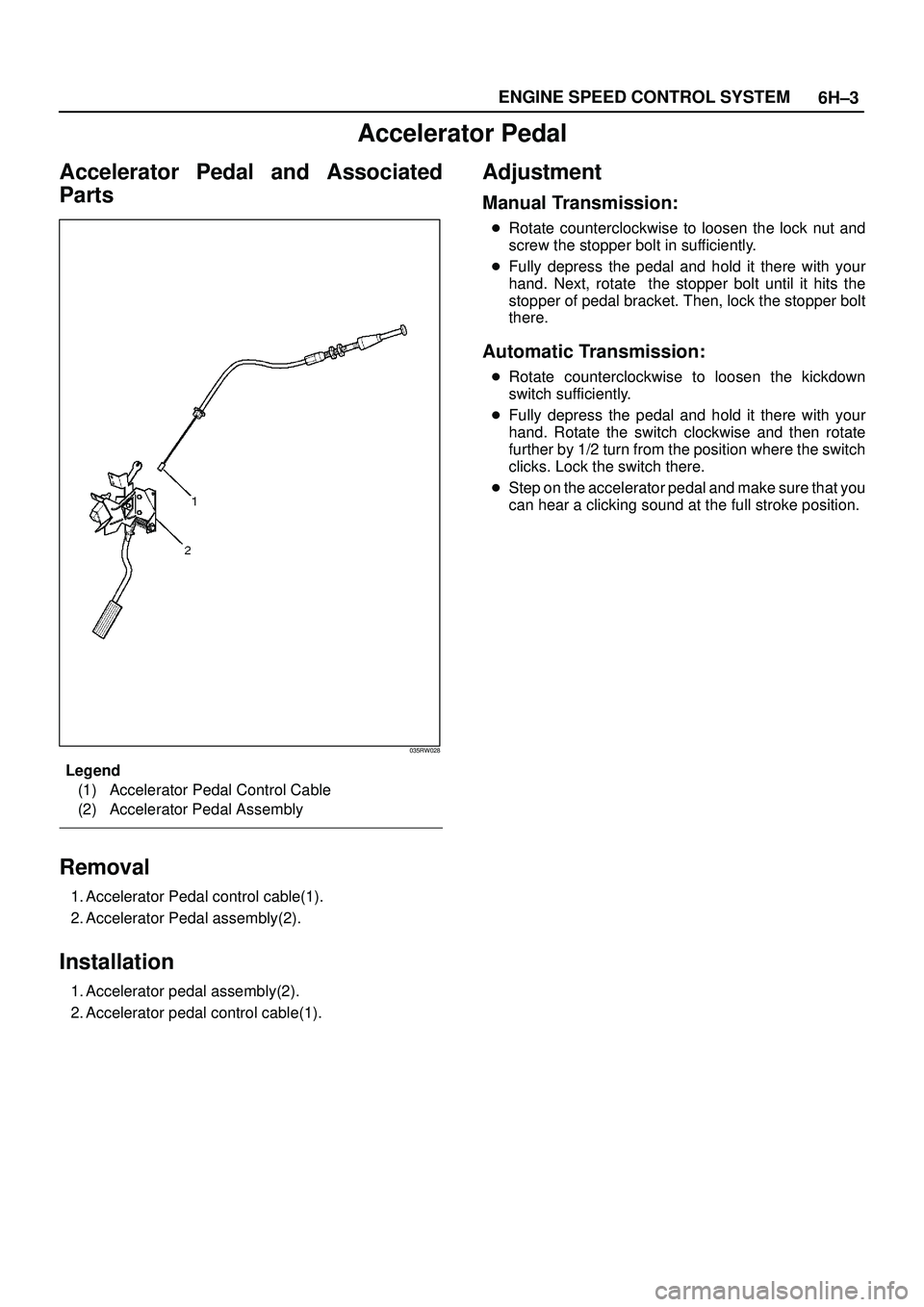
035RW028
Legend
(1) Accelerator Pedal Control Cable
(2) Accelerator Pedal Assembly
Removal
1. Accelerator Pedal control cable(1).
2. Accelerator Pedal assembly(2).
Installation
1. Accelerator pedal assembly(2).
2. Accelerator pedal control cable(1).
Adjustment
Manual Transmission:
�Rotate counterclockwise to loosen the lock nut and
screw the stopper bolt in sufficiently.
�Fully depress the pedal and hold it there with your
hand. Next, rotate the stopper bolt until it hits the
stopper of pedal bracket. Then, lock the stopper bolt
there.
Automatic Transmission:
�Rotate counterclockwise to loosen the kickdown
switch sufficiently.
�Fully depress the pedal and hold it there with your
hand. Rotate the switch clockwise and then rotate
further by 1/2 turn from the position where the switch
clicks. Lock the switch there.
�Step on the accelerator pedal and make sure that you
can hear a clicking sound at the full stroke position.
Page 1521 of 3573

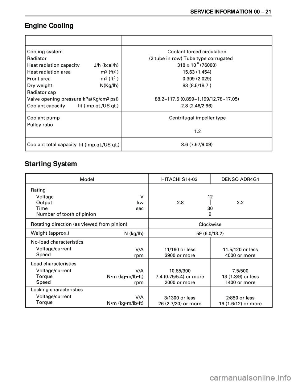
SERVICE INFORMATION 00 Ð 21
Engine Cooling
Starting System
Cooling system
Radiator
Heat radiation capacity
Heat radiation area
Front area
Dry weight
Radiator cap
Valve opening pressure
Coolant capacityCoolant forced circulation
(2 tube in row) Tube type corrugated
318 x 10 (76000)
15.63 (1.454)
0.309 (2.029)
83 (8.5/18.7 )
88.2~117.6 (0.899~1.199/12.78~17.05)
2.8 (2.46/2.96) J/h (kcal/h)
m
2 (ft2 )
m
2 (ft2 )
N(Kg/lb)
kPa(Kg/cm
2psi)
lit (Imp.qt./US qt.)
Coolant pump
Pulley ratioCentrifugal impeller type
1.2
Coolant total capacity
lit (Imp.qt./US qt.)8.6 (7.57/9.09)
6
Rating
Voltage
Output
Time
Number of tooth of pinion
Rotating direction (as viewed from pinion)
Weight (approx.)
No-load characteristics
Voltage/current
Speed
Load characteristics
Voltage/current
Torque
Speed
Locking characteristics
Voltage/current
Torque
Model HITACHI S14-03
V
kw
sec12
30
9
Clockwise
N (kg/lb)
59 (6.0/13.2)
V/A
rpm11/160 or less
3900 or more
V/A
N•m (kg•m/lb•ft)
rpm10.85/300
7.4 (0.75/5.4) or more
2000 or more
V/A
N•m (kg•m/lb•ft)3/1300 or less
26 (2.7/20) or more
11.5/120 or less
4000 or more
7.5/500
13 (1.3/9) or less
1400 or more
2/850 or less
16 (1.6/12) or more2.2 2.8DENSO ADR4G1
Page 1522 of 3573
00 Ð 22 SERVICE INFORMATION
Charging System
Model (HITACHI)
Rated voltage
Rated outputLR150 – 446
12
50LR180 – 501B
12
80
Rotating direction
(As viewed from pulled)
Pulley effective diameter
Weight (with pump)
Clockwise Clockwise
80 (3.15)
65(6.6 /14.6)
80 (3.15)
76(7.8 /17.2) V
A
mm(in)
N(Kg/lb)
Page 1528 of 3573

00 Ð 28 SERVICE INFORMATION
3. Remove the element from the solution and rinse it well
with running water.
Water pressure must not exceed 274 Kpa (2.8 kg/cm
2/40
Psi)
4. Dry the element in a well ventilated area.
An electric fan will hasten drying.
NOTE:
Do not use compressed air or an open flame to dry the
element quickly. Damage to the element will result.
It will usually take two or three days for the element to dry
completely. Therefore, it is a good idea to have a spare on
hand to use in the interim.
LUBRICATING SYSTEM
Main Oil Filter (Cartridge Type Paper Element)
Replacement Procedure
1. Loosen the drain plug to drain the engine oil.
2. Wait a few minutes and then retighten the drain plug.
3. Loosen the used oil filter by turning it counterclockwise
with the filter wrench.
4. Clean the oil cooler fitting face.
This will allow the new oil filter to seat properly.
5. Apply a light coat of engine oil to the O-ring.
6. Turn in the new oil filter until the filter O-ring is fitted
against the sealing face.
7. Use the filter wrench to turn in the filter an additional 1
and 1/4 turns.
Filter Wrench: 5-8840-0200-0
8. Check the engine oil level and replenish to the specified
level if required.
0.7 (0.62/0.74)
lit(Imp qt / US qt) Replenishment Engine Oil
9. Start the engine and check for oil leakage from the main
oil filter.