1998 ISUZU TROOPER air conditioning
[x] Cancel search: air conditioningPage 4 of 3573

PAGE BACK PAGE NEXT
THIS MALUAL INCLUDES THE FOLLOWING SECTIONS:
SECTION No. CONTRNTS
00 SERVICE INFORMATION
1A HEATING AND VENTILATION
1B AIR CONDITIONING
1D COMPRESSOR OVERHAUL
Page 16 of 3573

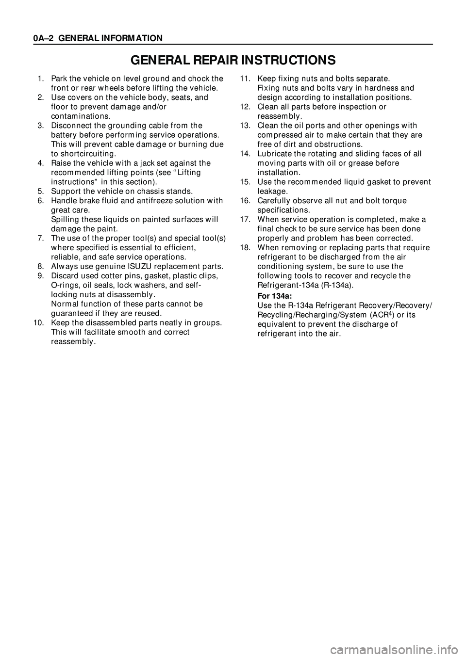
GENERAL REPAIR INSTRUCTIONS
1. Park the vehicle on level ground and chock the
front or rear wheels before lifting the vehicle.
2. Use covers on the vehicle body, seats, and
floor to prevent damage and/or
contaminations.
3. Disconnect the grounding cable from the
battery before performing service operations.
This will prevent cable damage or burning due
to shortcircuiting.
4. Raise the vehicle with a jack set against the
recommended lifting points (see ÒLifting
instructionsÓ in this section).
5. Support the vehicle on chassis stands.
6. Handle brake fluid and antifreeze solution with
great care.
Spilling these liquids on painted surfaces will
damage the paint.
7. The use of the proper tool(s) and special tool(s)
where specified is essential to efficient,
reliable, and safe service operations.
8. Always use genuine ISUZU replacement parts.
9. Discard used cotter pins, gasket, plastic clips,
O-rings, oil seals, lock washers, and self-
locking nuts at disassembly.
Normal function of these parts cannot be
guaranteed if they are reused.
10. Keep the disassembled parts neatly in groups.
This will facilitate smooth and correct
reassembly.11. Keep fixing nuts and bolts separate.
Fixing nuts and bolts vary in hardness and
design according to installation positions.
12. Clean all parts before inspection or
reassembly.
13. Clean the oil ports and other openings with
compressed air to make certain that they are
free of dirt and obstructions.
14. Lubricate the rotating and sliding faces of all
moving parts with oil or grease before
installation.
15. Use the recommended liquid gasket to prevent
leakage.
16. Carefully observe all nut and bolt torque
specifications.
17. When service operation is completed, make a
final check to be sure service has been done
properly and problem has been corrected.
18. When removing or replacing parts that require
refrigerant to be discharged from the air
conditioning system, be sure to use the
following tools to recover and recycle the
Refrigerant-134a (R-134a).
For 134a:
Use the R-134a Refrigerant Recovery/Recovery/
Recycling/Recharging/System (ACR
4) or its
equivalent to prevent the discharge of
refrigerant into the air.
0AÐ2 GENERAL INFORMATION
Page 26 of 3573

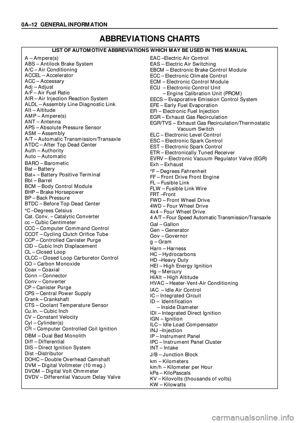
ABBREVIATIONS CHARTS
LIST OF AUTOMOTIVE ABBREVIATIONS WHICH MAY BE USED IN THIS MANUAL
A Ð Ampere(s)
ABS Ð Antilock Brake System
A/C Ð Air Conditioning
ACCEL Ð Accelerator
ACC Ð Accessary
Adj Ð Adjust
A/F Ð Air Fuel Ratio
AIR Ð Air Injection Reaction System
ALDL Ð Assembly Line Diagnostic Link
Alt Ð Altitude
AMP Ð Ampere(s)
ANT Ð Antenna
APS Ð Absolute Pressure Sensor
ASM Ð Assembly
A/T Ð Automatic Transmission/Transaxle
ATDC Ð After Top Dead Center
Auth Ð Authority
Auto Ð Automatic
BARO Ð Barometic
Bat Ð Battery
Bat+ Ð Battery Positive Terminal
Bbl Ð Barrel
BCM Ð Body Control Module
BHP Ð Brake Horsepower
BP Ð Back Pressure
BTDC Ð Before Top Dead Center
¡C ÐDegrees Celsius
Cat. Conv. Ð Catalytic Converter
cc Ð Cubic Centimeter
CCC Ð Computer Command Control
CCOT Ð Cycling Clutch Orifice Tube
CCP Ð Controlled Canister Purge
CID Ð Cubic Inch Displacement
CL Ð Closed Loop
CLCC Ð Closed Loop Carburetor Control
CO Ð Carbon Monoxide
Coax Ð Coaxial
Conn Ð Connector
Conv Ð Converter
CP Ð Canister Purge
CPS Ð Central Power Supply
Crank Ð Crankshaft
CTS Ð Coolant Temperature Sensor
Cu.In. Ð Cubic Inch
CV Ð Constant Velocity
Cyl Ð Cylinder(s)
C
3I Ð Computer Controlled Coil Ignition
DBM Ð Dual Bed Monolith
Diff Ð Differential
DIS Ð Direct Ignition System
Dist ÐDistributor
DOHC Ð Double Overhead Camshaft
DVM Ð Digital Voltmeter (10 meg.)
DVOM Ð Digital Volt Ohmmeter
DVDV Ð Differential Vacuum Delay Valve
EAC ÐElectric Air Control
EAS Ð Electric Air Switching
EBCM Ð Electronic Brake Control Module
ECC Ð Electronic Climate Control
ECM Ð Electronic Control Module
ECU Ð Electronic Control Unit
Ð Engine Calibration Unit (PROM)
EECS Ð Evaporative Emission Control System
EFE Ð Early Fuel Evaporation
EFI Ð Electronic Fuel Injection
EGR Ð Exhaust Gas Recirculation
EGR/TVS Ð Exhaust Gas Recirculation/Thermostatic
Vacuum Switch
ELC Ð Electronic Level Control
ESC Ð Electronic Spark Control
EST Ð Electronic Spark Control
ETR Ð Electronically Tuned Receiver
EVRV Ð Electronic Vacuum Regulator Valve (EGR)
Exh Ð Exhaust
¡F Ð Degrees Fahrenheit
FF Ð Front Drive Front Engine
FL Ð Fusible Link
FLW Ð Fusible Link Wire
FRT ÐFront
FWD Ð Front Wheel Drive
4WD Ð Four Wheel Drive
4x4 Ð Four Wheel Drive
4 A/T Ð Four Speed Automatic Transmission/Transaxle
Gal Ð Gallon
Gen Ð Generator
Gov Ð Governor
g Ð Gram
Harn Ð Harness
HC Ð Hydrocarbons
HD ÐHeavy Duty
HEI Ð High Energy Ignition
Hg Ð Mercury
HiAlt Ð High Altitude
HVAC Ð Heater-Vent-Air Conditioning
IAC Ð Idle Air Control
IC Ð Integrated Circuit
ID Ð Identification
Ð Inside Diameter
IDI Ð Integrated Direct Ignition
IGN Ð Ignition
ILC Ð Idle Load Compensator
INJ ÐInjection
IP Ð Instrument Panel
IPC Ð Instrument Panel Cluster
INT Ð Intake
J/B Ð Junction Block
km Ð Kilometers
km/h Ð Kilometer per Hour
kPa Ð KiloPascals
KV Ð Kilovolts (thousands of volts)
KW Ð Kilowatts
0AÐ12 GENERAL INFORMATION
Page 42 of 3573

SERVICE INFORMATION 00 Ð 3
TROUBLESHOOTING
CONTENTS
PAGE
Circuit Diagram.........................................................00Ð 4
Heating Cycle Troubleshooting............................................00Ð16
Fan Control Knob (Fan Switch)............................................00Ð17
Blower Motor Does Not Run............................................00Ð18
Blower Motor Does Not Run In Certain Position............................00Ð19
Blower Motor Does Not Stop at ÒOFFÓ Position............................00Ð19
Ceramic Heater.........................................................00Ð20
Ceramic Heater Does Not Operate.......................................00Ð21
Ceramic Heater Does Not Stop..........................................00Ð22
Air Conditioning Cycle Troubleshooting.....................................00Ð23
Checking Refrigerant System with Manifold Gauge.........................00Ð24
Magnetic Clutch........................................................00Ð27
6VD1/6VE1 Engine....................................................00Ð27
4JG2 Engine.........................................................00Ð31
4JX1 Engine..........................................................00Ð34
Condenser Fan..........................................................00Ð37
Condenser Fan Does Not Run...........................................00Ð38
Condenser Fan Does Not Stop..........................................00Ð39
Compressor Troubleshooting.............................................00Ð40
Individual Inspection.....................................................00Ð41
Page 62 of 3573

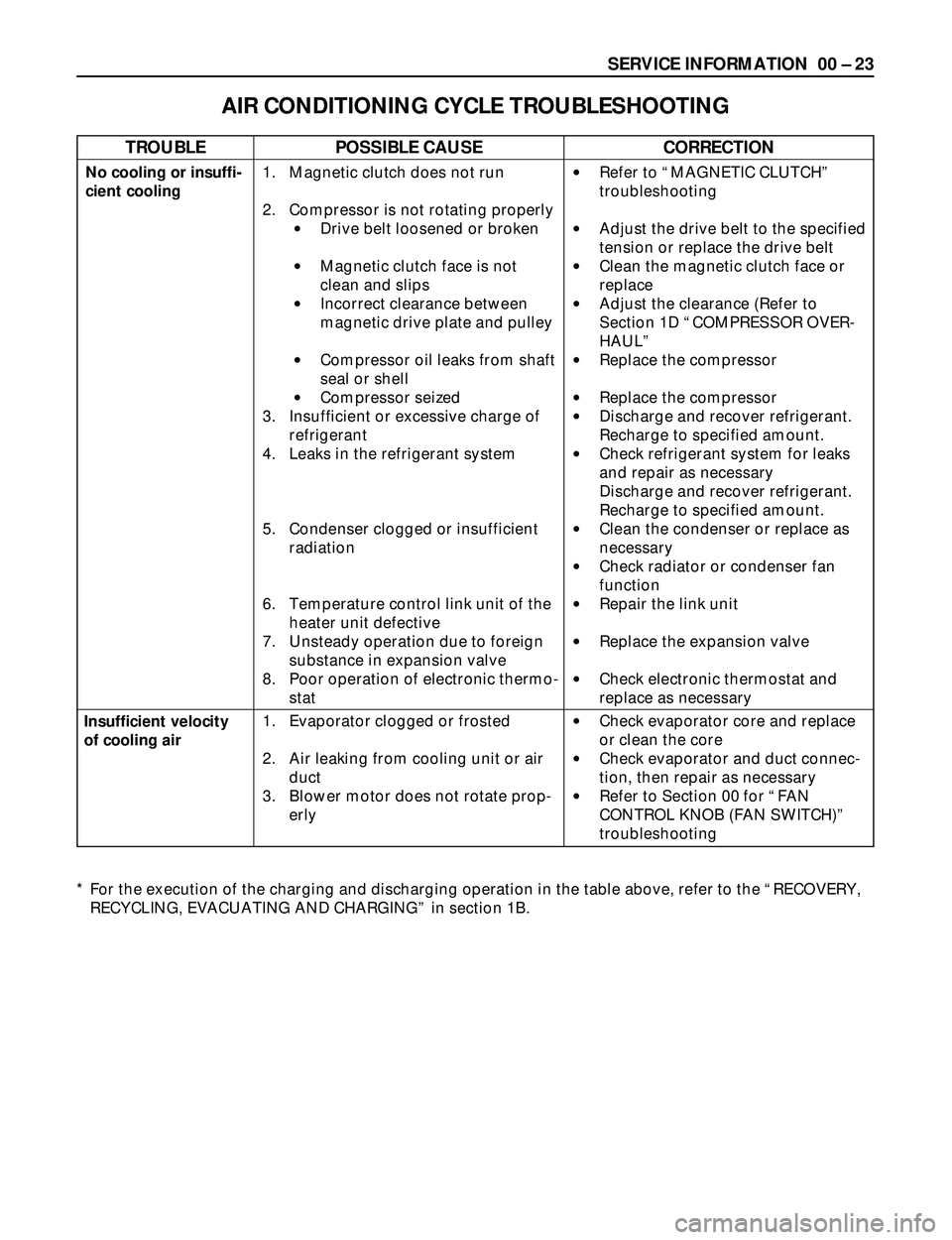
SERVICE INFORMATION 00 Ð 23
AIR CONDITIONING CYCLE TROUBLESHOOTING
No cooling or insuffi-
cient cooling
Insufficient velocity
of cooling air1. Magnetic clutch does not run
2. Compressor is not rotating properly
·Drive belt loosened or broken
·Magnetic clutch face is not
clean and slips
·Incorrect clearance between
magnetic drive plate and pulley
·Compressor oil leaks from shaft
seal or shell
·Compressor seized
3. Insufficient or excessive charge of
refrigerant
4. Leaks in the refrigerant system
5. Condenser clogged or insufficient
radiation
6. Temperature control link unit of the
heater unit defective
7. Unsteady operation due to foreign
substance in expansion valve
8. Poor operation of electronic thermo-
stat
1. Evaporator clogged or frosted
2. Air leaking from cooling unit or air
duct
3. Blower motor does not rotate prop-
erly·Refer to ÒMAGNETIC CLUTCHÓ
troubleshooting
·Adjust the drive belt to the specified
tension or replace the drive belt
·Clean the magnetic clutch face or
replace
·Adjust the clearance (Refer to
Section 1D ÒCOMPRESSOR OVER-
HAULÓ
·Replace the compressor
·Replace the compressor
·Discharge and recover refrigerant.
Recharge to specified amount.
·Check refrigerant system for leaks
and repair as necessary
Discharge and recover refrigerant.
Recharge to specified amount.
·Clean the condenser or replace as
necessary
·Check radiator or condenser fan
function
·Repair the link unit
·Replace the expansion valve
·Check electronic thermostat and
replace as necessary
·Check evaporator core and replace
or clean the core
·Check evaporator and duct connec-
tion, then repair as necessary
·Refer to Section 00 for ÒFAN
CONTROL KNOB (FAN SWITCH)Ó
troubleshooting
* For the execution of the charging and discharging operation in the table above, refer to the ÒRECOVERY,
RECYCLING, EVACUATING AND CHARGINGÓ in section 1B.
TROUBLEPOSSIBLE CAUSECORRECTION
Page 64 of 3573

RESULT SYMPTOM TROUBLE CAUSE CORRECTION
SERVICE INFORMATION 00 Ð 25
Reduced or no air flow through
the condenser
No bubbles in sight glass when
condenser is cooled by water
(Insufficient cooling)
After stopping air conditioning,
pressure drops approx. 196 kPa
(28 PSI) quickly
Insufficient cooling and excessive
bubbles in the sight glass
Low pressure gauge indicates
vacuum
Frost or dew on refrigerant line
before and after receiver/ drier or
expansion valve, and low pres-
sure gauge indicates vacuum
After turning off air conditioning,
high and low pressure gauge
balanced quickly
Low pressure gauge is lowered
after condenser is cooled by
water
Low pressure hose temperature
around the compressor refriger-
ant line connector is lower than
around evaporator
After turning off air conditioning,
high and low pressure gauge is
balanced quickly
Air conditioning turns off before
passenger compartment is suffi-
ciently cool·Condenser clogged or dirty
·Radiator (condenser) fan
does not operate properly
·Excessive refrigerant in
system
·Air in system
·Insufficient refrigerant in
system
·Clogged or defective expan-
sion valve
·Restriction caused by debris
or moisture in receiver/drier
·Compressor seal defective
·Poor compression due to
defective compressor gasket
·Excessive refrigerant in
system
·Unsatisfactory valve opera-
tion due to defective temper-
ature sensor of expansion
valve
·Expansion valve opens too
long
·Compressor gasket is defec-
tive
·Electronic thermostat defec-
tive·Clean
·Check cooling fan
operation
·Check sight glass.
(See ÒReading Sight
GlassÓ)
·Discharge and
recover refrigerant.
Recharge to speci-
fied amount
·Evacuate and
charge refrigerant
system
·Check sight glass.
(See ÒReading Sight
GlassÓ)
·Check for leaks
·Discharge and
recover refrigerant.
Recharge to speci-
fied amount
·Replace the expan-
sion valve
·Check system for
restriction and
replace
receiver/drier
·Replace or repair
compressor
·Discharge and
recover refrigerant
Recharge to speci-
fied amount
·Replace the expan-
sion valve
·Replace
·Check the electronic
thermostat and
replace as neces-
saryDischarge
(High) pres-
sure gauge
abnormally
high
Discharge
(High) pres-
sure gauge
abnormally
low
Suction
(Low) pres-
sure gauge
abnormally
high
* For the charging and discharging operations in the table above, refer to ÒRECOVERY, RECYCLING,
EVACUATION AND CHARGINGÓ in this section.
Page 66 of 3573

SERVICE INFORMATION 00 Ð 27
MAGNETIC CLUTCH
When the A/C switch and the fan control knob (fan
switch) are turned on with the engine running,
current flows through the thermostat and the com-
pressor relay to activate the magnetic clutch.
The air conditioning can be stopped by turning off
the A/C switch or the fan control knob (fan switch).
However, even when the air conditioning is in oper-ation, the electronic thermostat, the pressure switch
or the PCM (6VD1/6VE1 Engine) is used to stop the
air conditioning temporarily by turning off the mag-
netic clutch in the prearranged conditions to reduce
the engine load which is being caused by the rise in
the engine coolant temperature, and the accelera-
tion of the vehicle, etc.
123
45 6
RELAY; A/C
B-36C-20
10A
A/C FL-1
80A
MAIN
1
2
B-2
C-25
2
4
X-5
1
3 (3)
(1)
4
13
24
1
A/C SW.
FAN SW.
I-23
PRESSURE
SW.
RELAY;
THERMOSTAT
B-2
X-7 C-25
C-1C-3E-3I-23
BATTERY
X-7
RELAY: A/C
COMPRESSOR
1
E-3
MAGNETIC
CLUTCHMg
OFF
I-18
2
6
1
321123
12
3412
11
213
5 46
I-18
X-5
B-1(LHD) (RHD)
B-1
1
2 34
W/ CONDENSER
FAN
2
4
1
3
C-3PCM (E15)
C-1PCM (B14)
3
1
2
ELECTRONIC
THERMOSTAT
I-42
I-42B-36
Pin number with ( ); RHD
A1 A2 A3 A4 A5 A6 A7 A8 A9A10 A11 A12 A13 A14 A15 A16B1 B2 B3 B4 B5 B6 B7 B8 B9B10 B11 B12 B13 B14 B15 B16E1 E2 E3 E4 E5 E6 E7 E8 E9E10 E11 E12 E13 E14 E15 E16F1 F2 F3 F4 F5 F6 F7 F8 F9F10 F11 F12 F13 F14 F15 F16
6VD1/6VE1 ENGINE
D08RY00295
Page 89 of 3573

00 Ð 50 SERVICE INFORMATION
Legend
1. Clutch Driver
2. Rotor Bearing Retainer
3. Pulley Rotor and Bearing
Assembly
4. Clutch Coil Assembly
5. Connector
6. Shaft Seal Parts
7. Pump Assembly
8. High Pressure Relief Valve
9. Shipping Cap
10. Special 134a Suction Port
11. Special 134a Discharge Port
Caution
The operations described below are based
on bench overhaul with the compressor
removed from the vehicle, except as noted.
They have been prepared in order of
accessibility of the components. When a
compressor is removed from the vehicle for
servicing, the amount of PAG lubricant
remaining in the compressor should be
drained, measured and recorded. This PAG
lubricant should then be discarded and an
equal amount of new PAG lubricant added to
the compressor.
The service compressor is shipped without
PAG oil. When service procedures require,
use only Isuzu approved PAG oil.
HEATING, VENTILATION AND AIR CONDITIONING(HVAC)
1
2
3
4
5
68
97
10
11
871RW002