1998 ISUZU TROOPER turn signal
[x] Cancel search: turn signalPage 133 of 3573

AIR CONDITIONING 1B Ð 7
EVAPORATOR
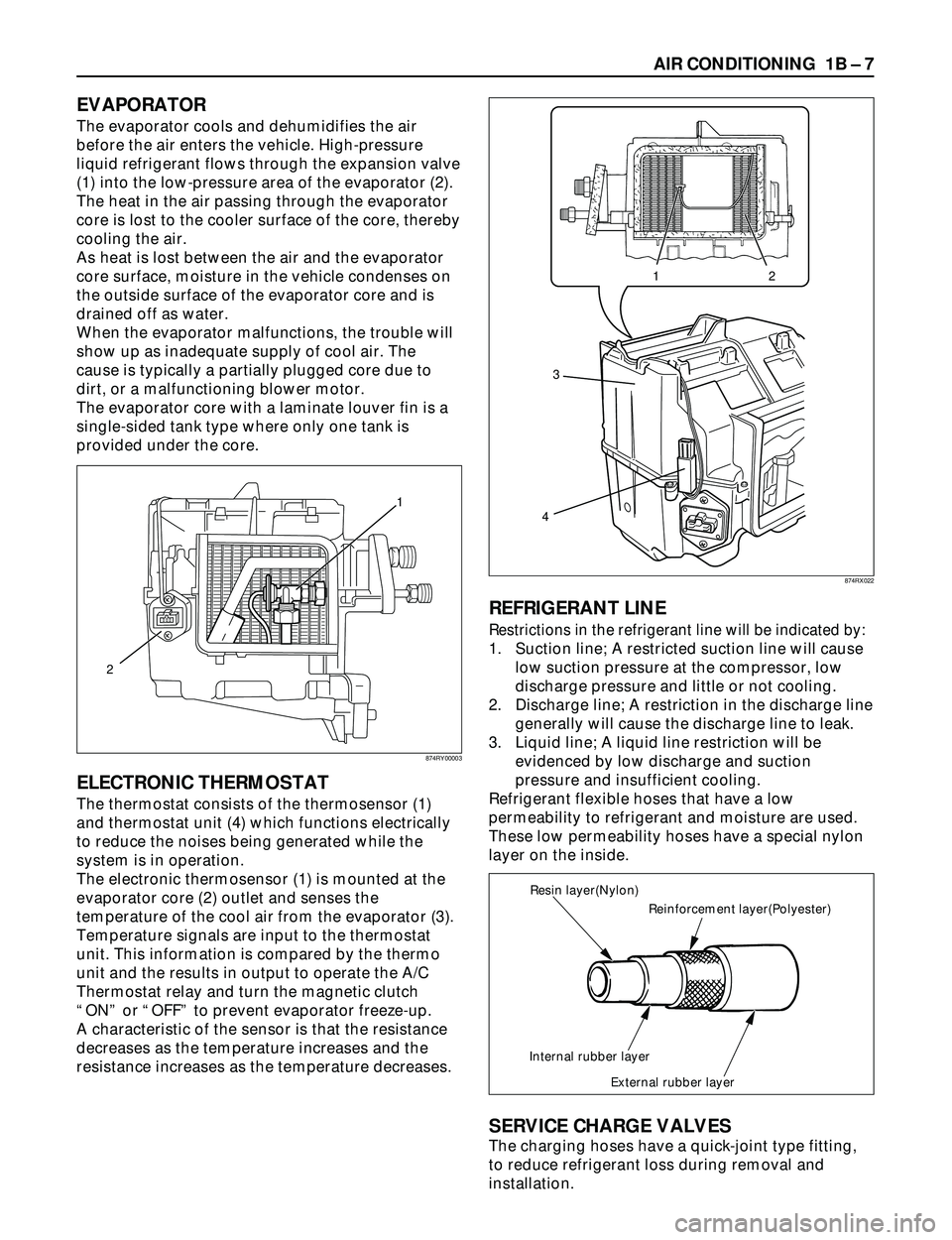
The evaporator cools and dehumidifies the air
before the air enters the vehicle. High-pressure
liquid refrigerant flows through the expansion valve
(1) into the low-pressure area of the evaporator (2).
The heat in the air passing through the evaporator
core is lost to the cooler surface of the core, thereby
cooling the air.
As heat is lost between the air and the evaporator
core surface, moisture in the vehicle condenses on
the outside surface of the evaporator core and is
drained off as water.
When the evaporator malfunctions, the trouble will
show up as inadequate supply of cool air. The
cause is typically a partially plugged core due to
dirt, or a malfunctioning blower motor.
The evaporator core with a laminate louver fin is a
single-sided tank type where only one tank is
provided under the core.
ELECTRONIC THERMOSTAT
The thermostat consists of the thermosensor (1)
and thermostat unit (4) which functions electrically
to reduce the noises being generated while the
system is in operation.
The electronic thermosensor (1) is mounted at the
evaporator core (2) outlet and senses the
temperature of the cool air from the evaporator (3).
Temperature signals are input to the thermostat
unit. This information is compared by the thermo
unit and the results in output to operate the A/C
Thermostat relay and turn the magnetic clutch
ÒONÓ or ÒOFFÓ to prevent evaporator freeze-up.
A characteristic of the sensor is that the resistance
decreases as the temperature increases and the
resistance increases as the temperature decreases.
REFRIGERANT LINE
Restrictions in the refrigerant line will be indicated by:
1. Suction line; A restricted suction line will cause
low suction pressure at the compressor, low
discharge pressure and little or not cooling.
2. Discharge line; A restriction in the discharge line
generally will cause the discharge line to leak.
3. Liquid line; A liquid line restriction will be
evidenced by low discharge and suction
pressure and insufficient cooling.
Refrigerant flexible hoses that have a low
permeability to refrigerant and moisture are used.
These low permeability hoses have a special nylon
layer on the inside.
SERVICE CHARGE VALVES
The charging hoses have a quick-joint type fitting,
to reduce refrigerant loss during removal and
installation.
12
3
4
Reinforcement layer(Polyester) Resin layer(Nylon)
Internal rubber layer
External rubber layer
1
2
874RY00003874RX022
Page 212 of 3573

1BÐ86 AIR CONDITIONING
Legend
(1) Out put Axis
(2) Motor
(3) Printed Circuit Board
(4) Sliding Contact
The mode and mix actuators are common actuators
with the built-in potentiometer. For the intake
actuator, the contact switch type is selected.
The potentiometer is a register assembled to the
printed circuit board of the mix and mode
actuators. It detects the air mix door position
specified by rotation of the output axis as a ratio of
the variable terminal (VM) voltage against the
reference voltage (VDD: 5V), then signals the value
to the automatic heater/air conditioner control unit.¥ Movement of Mix Actuator
Position of the air mix door is determined by the
controller on the automatic heater/air conditioner
control unit.
As the heat or cool side of the controller is
grounded, the transistor on the driver is activated
and, thus, the motor rotation is turned on. The
sliding contact connected to the motor sends the
position detection signal from the potentiometer
to the automatic heater/air conditioner control
unit. As the set temperature and interior
temperature are balanced, the controller returns
to the neutral and the motor rotation is stopped.
12
43
860RW026
C01RX016
M
N 3
2
7
6
8
98 43
65 21
7
Potentiometer
ConnectionPosition
Detection
Block Automatic Heater / Air
Conditioner Control Unit
Controller
Sliding Contact
Full Heate PositionTerminal PlateFull Cool PositionDriver
Cool Side Heat Side
C01RX005
Full cool
Full cool0 0 0.5 1.0
50 100%
Aperture of air mix doorVoltage ratio VM/VDD
Full heat Full heat
VDD
VM +
–
I-45 Rotation
(+) side (Ð) side direction Remarks
8 6 Clockwise Full heat side
6 8 Counter Full cool side
clockwise
Page 213 of 3573

AIR CONDITIONING 1BÐ87
¥ Movement of Mode Actuator
As target position of the mode door is decided on
the controller of the control unit, the control unit
reads the position detection signal from the
actuator to select the clockwise or counter
clockwise motor rotation direction.
Grounding the controller VENT or DEF side after
the direction selection activates the transistor on
the driver, thus turning on the motor rotation.
Accompanying the motor rotation, the sliding
contact rotates, too. When the target position is
reached, the controller on the control unit returns
to the neutral and the motor stops.¥ Movement of Intake Actuator
The controller on the automatic heater/air
conditioner control unit selects an intake mode to
be used.
As the Terminal No.5 is grounded via the
sliding contact on the terminal plate, the
transistor on the driver is activated, thus turning
on the motor rotation. Then, accompanying
move of the motor, the sliding contact rotates
until grounding of the Terminal No.5 is
removed, thus stopping the motor.I-49
I-49
DriverController
DEF side
VENT
side
Position
detection
block Control unit
Sliding
contact
Actuator side42
983
7
78910
HLHL
HHHL
HHLL
HHLH
HLLH
HLHH
LLHH
LHHH
LHLH 61
5
Interconnected
motor
VENTVENT
Mid point between VENT - B/L
B/L
Mid point between B/L - FOOT
FOOT
Mid point between FOOT - D/F
D/F
Mid point between D/F - DEF
DEFDEF
7
8
9
10 2 6
7
8
3
4
9
5
1
C01RX017
M
+6 1 2
65 4 3
REC
MIX
FRESH
Com1
2
5
3
4++
Ð
Terminal PlateAuto A/C
Control Unit (Actuator Side)
Driver Controller
Sliding Contact
Connected
C01RX006
Conducting pin Rotation
(+) side (Ð) side direction Remarks
5 1 Clockwise VENT to
DEF direction
1 5 Counter DEF to
clockwise VENT diction
Grounding Rotation
terminal direction Remarks
No.5 Clockwise RE-CIRCULA
TION
®MIX
®FRESH I-49
Page 214 of 3573

1BÐ88 AIR CONDITIONING
OVERVIEW OF AUTOMATIC CONTROL OF
FULL AUTOMATIC AIR CONDITIONER
The full automatic heater and air conditioner on this
vehicle has the following features:
¥ Interior temperature control.
¥ Air flow control.
¥ Mode (blow port) control.
¥ Intake (switching between fresh air and interior
air) control.
¥ Heater start timing control.
¥ Cooler start timing control.
¥ Evaporator anti-freeze control.
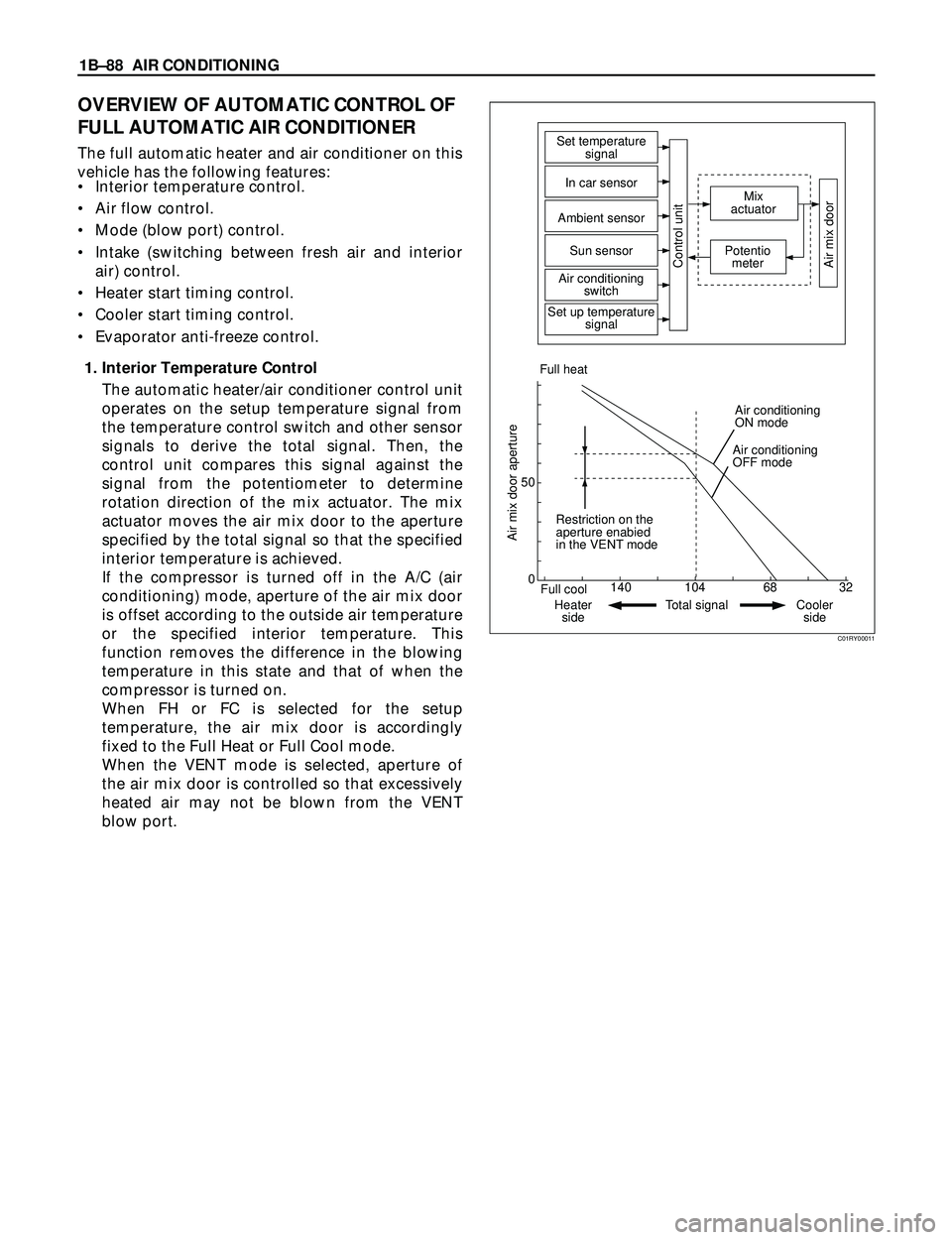
1. Interior Temperature Control
The automatic heater/air conditioner control unit
operates on the setup temperature signal from
the temperature control switch and other sensor
signals to derive the total signal. Then, the
control unit compares this signal against the
signal from the potentiometer to determine
rotation direction of the mix actuator. The mix
actuator moves the air mix door to the aperture
specified by the total signal so that the specified
interior temperature is achieved.
If the compressor is turned off in the A/C (air
conditioning) mode, aperture of the air mix door
is offset according to the outside air temperature
or the specified interior temperature. This
function removes the difference in the blowing
temperature in this state and that of when the
compressor is turned on.
When FH or FC is selected for the setup
temperature, the air mix door is accordingly
fixed to the Full Heat or Full Cool mode.
When the VENT mode is selected, aperture of
the air mix door is controlled so that excessively
heated air may not be blown from the VENT
blow port.
0 50
140 104 68 32
Air mix door aperture
Full cool
Heater
side Restriction on the
aperture enabied
in the VENT modeAir conditioning
ON mode Full heatSet temperature
signal
Mix
actuator
Potentio
meter
Air mix door
In car sensor
Ambient sensor
Sun sensor
Control unitAir conditioning
switch
Set up temperature
signal
Air conditioning
OFF mode
Total signal Cooler
side
C01RY00011
Page 216 of 3573

1BÐ90 AIR CONDITIONING
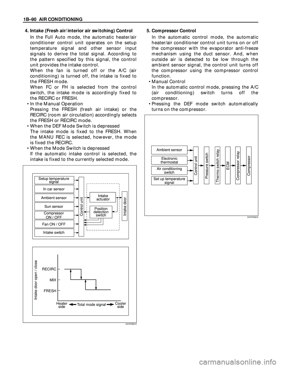
4. Intake (Fresh air/interior air switching) Control
In the Full Auto mode, the automatic heater/air
conditioner control unit operates on the setup
temperature signal and other sensor input
signals to derive the total signal. According to
the pattern specified by this signal, the control
unit provides the intake control.
When the fan is turned off or the A/C (air
conditioning) is turned off, the intake is fixed to
the FRESH mode.
When FC or FH is selected from the control
switch, the intake mode is accordingly fixed to
the RECIRC or FRESH.
¥ In the Manual Operation
Pressing the FRESH (fresh air intake) or the
RECIRC (room air circulation) accordingly selects
the FRESH or RECIRC mode.
¥ When the DEF Mode Switch is depressed
The intake mode is fixed to the FRESH. When
the MANU REC is selected, however, the mode
is fixed the RECIRC.
¥ When the Mode Switch is depressed
If the automatic intake control is selected, the
intake is fixed to the currently selected mode.5. Compressor Control
In the automatic control mode, the automatic
heater/air conditioner control unit turns on or off
the compressor with the evaporator anti-freeze
mechanism using the duct sensor. And, when
outside air is detected to be low through the
ambient sensor signal, the control unit turns off
the compressor using the compressor control
function.
¥ Manual Control
In the automatic control mode, pressing the A/C
(air conditioning) switch turns off the
compressor.
¥ Pressing the DEF mode switch automatically
turns on the compressor.
Intake door open / close
RECIRC Setup temperature
signal
Intake
actuator
Position
detection
switch
In car sensor
Ambient sensor
Sun sensor
Compressor
ON / OFF
Fan ON / OFF
Intake switch
Control unit
Intake door
MIX
FRESH
Heater
sideCooler
side Total mode signal
C01RY00012
Ambient sensor
Control unit
Pressure switch
Thermo switch relay
ECM
Compressor relay
Compressor
Electronic
thermostat
Air conditioning
switch
Set up temperature
signal
C01RY00010
Page 217 of 3573

AIR CONDITIONING 1BÐ91
6. Heating Start Timing Control
When the automatic heater/air conditioner is
started, heating is turned on under following
conditions.
·The detected temperature of thermo unit is
136¡F or less.
·The temperature setting signal and the total
signal by each sensor meet the condition of
heating.
When the detected temperature by the coolant
temperature sensor is 136¡F or less the blower
fan motor is set to work at low speed and the
"DEF" mode is selected.
When the detected temperature by the coolant
temperature sensor is 77¡F or more, the blow
mode changes automatic control. And the
blower fan speed is controlled to be lineally up
from "LO" to "MAX HI".7. Cooling Start Timing Control
When the automatic heater/air conditioner is
started, cooling is turned on under following
conditions.
·The in car sensor is 86¡F or more.
·The temperature setting signal and the signals
from each sensor meet the specified condition.
The blower fan speed is set to "LO" for
maximum 7 seconds when cooling start
conditions meet, and then, is controlled to be
lineally up to "MAX HI" by 5.32%/S.
Ignition swich
"ON"
Time
Blower voltage to turn
on the cooling
7 SEC maximum3 SEC
100%
(MAX HI)
33.5%
(LO)5.32%/S
C06RY00001
33.5%
(LO)
2.63%/S
Mode
DEF
Auto
Mode
100%
(MAX HI)
Ignition
switch "ON"
Thermo Unit 58¡C(Gasoline)
52¡C(Diesel) Time
840RY00009
Page 292 of 3573

00 – 10 SERVICE INFORMATION
Problem Possible Cause Correction
STEERING COLUMN (CONT.)
TURN SIGNAL SWITCH
This troubleshooting covers mechanical problems only. See Section 8 for turn signal switch electrical
diagnosis.
Turn Signal Will Not Stay
in Turn Position
Turn Signal Will Not
Cancel
Turn Signal Difficult to
Operate
Turn Signal Will Not
Indicate Lane Change
Hezard Switch Cannot Be
Turned Off
No Turn Signal Lights
Front or Rear Turn Signal
Lights Not Flashing1. Foreign material or loose parts
preventing movement of yoke.
2. Broken or missing detent or canceling
spring.
1. Loose switch mounting screws.
2. Switch or anchor bosses broken.
3. Broken, missing or out of position
detent, return or canceling spring.
4. Worn canceling cam.
1. Turn signal switch arm loose.
2. Yoke broken or distorted.
3. Loose or misplaced springs.
4. Foreign parts and/or material.
5. Loose turn signal switch mounting
screws.
1. Broken lane change pressure pad or
spring hanger.
2. Broken, missing or misplaced lane
change spring.
3. Base of wire damaged.
1. Foreign material between hazard
switch to turn signal switch body.
1. Electrical failure in chassis harness.
2. Inoperative turn signal flasher unit.
3. Loose chassis harness connector.
1. Burned-out damaged turn signal bulb.
2. High resistance connection to ground
at bulb socket.
3. Loose chassis harness connector.Repair or replace signal switch.
Replace signal switch.
Tighten mounting screws.
Replace turn signal switch.
Replace turn signal switch.
Replace turn signal switch.
Tighten arm screw.
Replace turn signal switch.
Replace turn signal switch.
Repair turn signal switch.
Tighten mounting screws.
Replace turn signal switch.
Replace turn signal switch.
Replace turn signal switch.
Repair or replace hazard
switch.
Refer to Section 8 “Electrical
Troubleshooting”.
Replace flasher unit.
Repair loose connector.
Replace bulb.
Repair bulb socket.
Repair loose connector.
Page 542 of 3573

4B1±9 DRIVE LINE CONTROL SYSTEM (SHIFT ON THE FLY)
Retrial
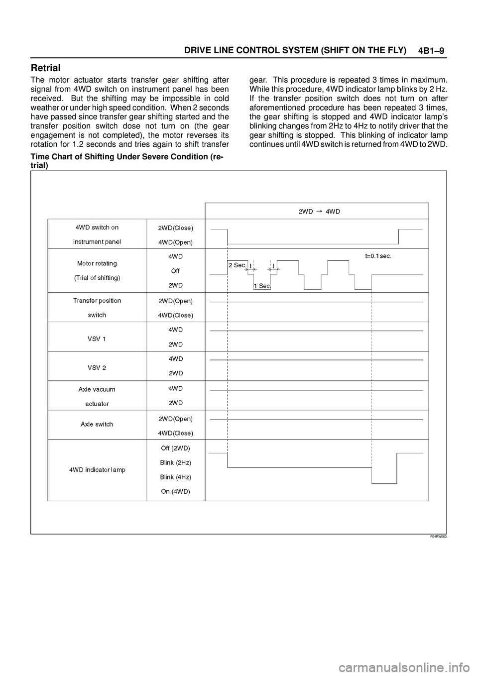
The motor actuator starts transfer gear shifting after
signal from 4WD switch on instrument panel has been
received. But the shifting may be impossible in cold
weather or under high speed condition. When 2 seconds
have passed since transfer gear shifting started and the
transfer position switch dose not turn on (the gear
engagement is not completed), the motor reverses its
rotation for 1.2 seconds and tries again to shift transfergear. This procedure is repeated 3 times in maximum.
While this procedure, 4WD indicator lamp blinks by 2 Hz.
If the transfer position switch does not turn on after
aforementioned procedure has been repeated 3 times,
the gear shifting is stopped and 4WD indicator lamp's
blinking changes from 2Hz to 4Hz to notify driver that the
gear shifting is stopped. This blinking of indicator lamp
continues until 4WD switch is returned from 4WD to 2WD.
Time Chart of Shifting Under Severe Condition (re-
trial)
F04RW003