1998 ISUZU TROOPER ABS
[x] Cancel search: ABSPage 25 of 3573
GENERAL INFORMATION 0AÐ11
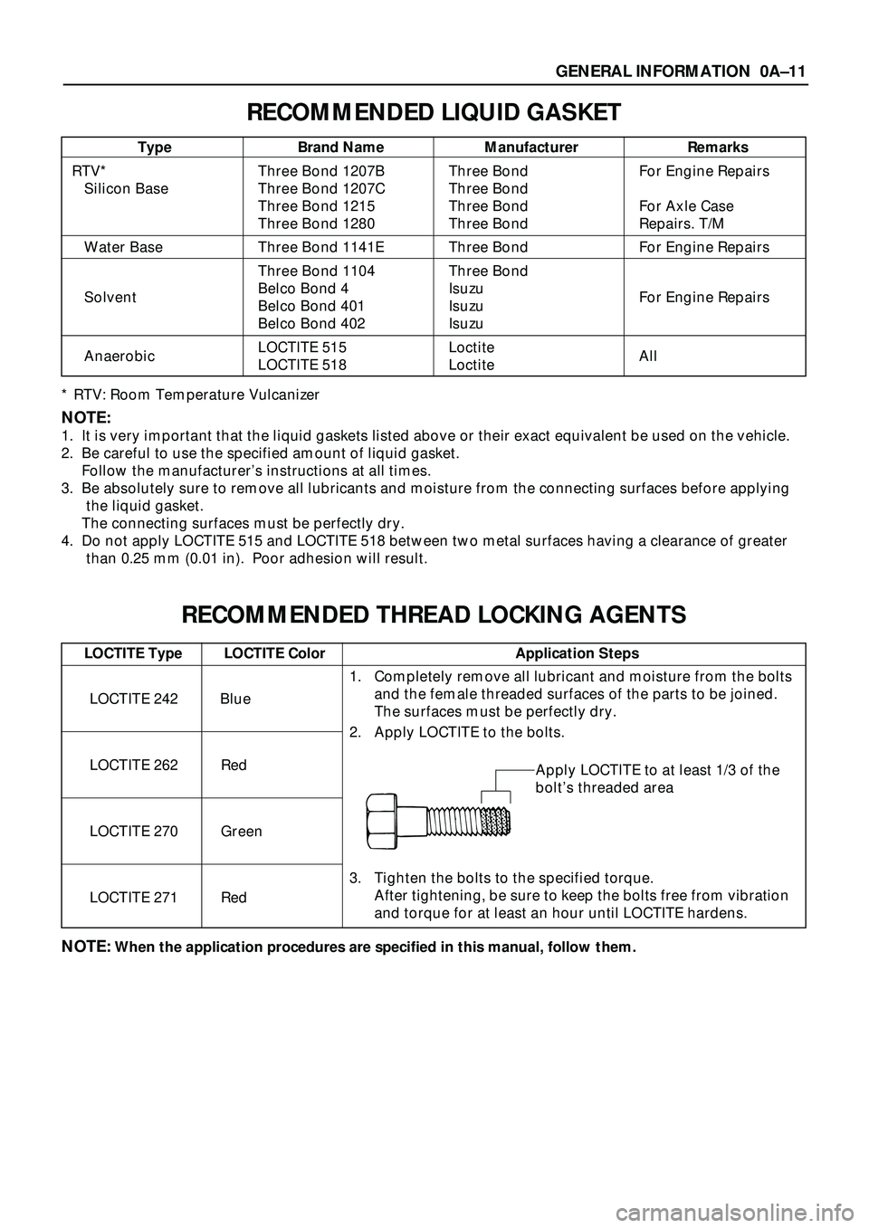
RECOMMENDED LIQUID GASKET
* RTV: Room Temperature Vulcanizer
NOTE:
1. It is very important that the liquid gaskets listed above or their exact equivalent be used on the vehicle.
2. Be careful to use the specified amount of liquid gasket.
Follow the manufacturerÕs instructions at all times.
3. Be absolutely sure to remove all lubricants and moisture from the connecting surfaces before applying
the liquid gasket.
The connecting surfaces must be perfectly dry.
4. Do not apply LOCTITE 515 and LOCTITE 518 between two metal surfaces having a clearance of greater
than 0.25 mm (0.01 in). Poor adhesion will result.
RECOMMENDED THREAD LOCKING AGENTS
NOTE:When the application procedures are specified in this manual, follow them.
Type Brand Name Manufacturer Remarks
RTV* Three Bond 1207B Three Bond For Engine Repairs
Silicon Base Three Bond 1207C Three Bond
Three Bond 1215 Three Bond For Axle Case
Three Bond 1280 Three Bond Repairs. T/M
Water Base Three Bond 1141E Three Bond For Engine Repairs
Three Bond 1104 Three Bond
Belco Bond 4 Isuzu
Solvent
Belco Bond 401 Isuzu For Engine Repairs
Belco Bond 402 Isuzu
LOCTITE 515 Loctite
Anaerobic
LOCTITE 518 Loctite All
LOCTITE Type LOCTITE Color Application Steps
LOCTITE 242 Blue
LOCTITE 262 Red
LOCTITE 270 Green
LOCTITE 271 Red
1. Completely remove all lubricant and moisture from the bolts
and the female threaded surfaces of the parts to be joined.
The surfaces must be perfectly dry.
2. Apply LOCTITE to the bolts.
Apply LOCTITE to at least 1/3 of the
boltÕs threaded area
3. Tighten the bolts to the specified torque.
After tightening, be sure to keep the bolts free from vibration
and torque for at least an hour until LOCTITE hardens.
Page 26 of 3573
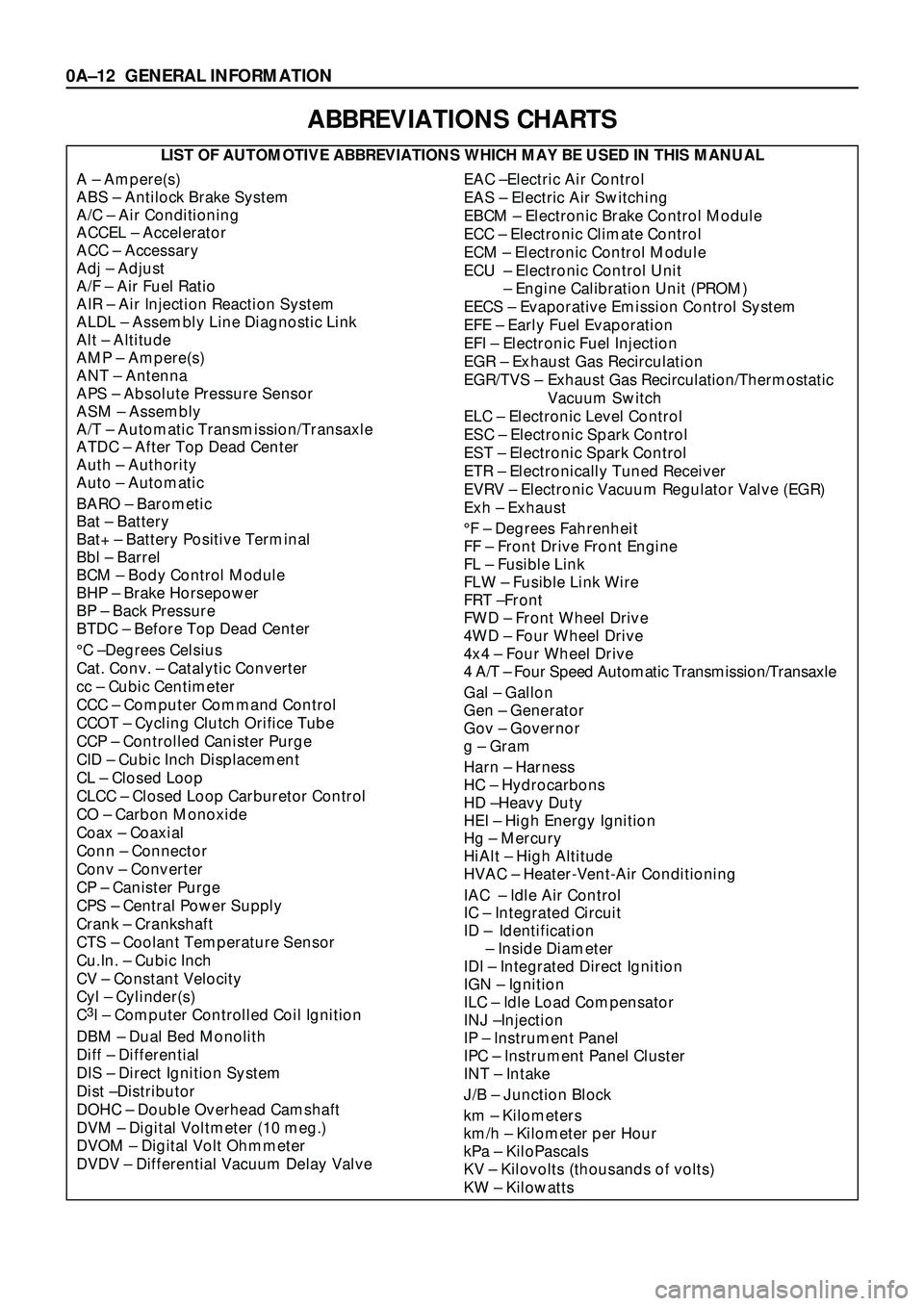
ABBREVIATIONS CHARTS
LIST OF AUTOMOTIVE ABBREVIATIONS WHICH MAY BE USED IN THIS MANUAL
A Ð Ampere(s)
ABS Ð Antilock Brake System
A/C Ð Air Conditioning
ACCEL Ð Accelerator
ACC Ð Accessary
Adj Ð Adjust
A/F Ð Air Fuel Ratio
AIR Ð Air Injection Reaction System
ALDL Ð Assembly Line Diagnostic Link
Alt Ð Altitude
AMP Ð Ampere(s)
ANT Ð Antenna
APS Ð Absolute Pressure Sensor
ASM Ð Assembly
A/T Ð Automatic Transmission/Transaxle
ATDC Ð After Top Dead Center
Auth Ð Authority
Auto Ð Automatic
BARO Ð Barometic
Bat Ð Battery
Bat+ Ð Battery Positive Terminal
Bbl Ð Barrel
BCM Ð Body Control Module
BHP Ð Brake Horsepower
BP Ð Back Pressure
BTDC Ð Before Top Dead Center
¡C ÐDegrees Celsius
Cat. Conv. Ð Catalytic Converter
cc Ð Cubic Centimeter
CCC Ð Computer Command Control
CCOT Ð Cycling Clutch Orifice Tube
CCP Ð Controlled Canister Purge
CID Ð Cubic Inch Displacement
CL Ð Closed Loop
CLCC Ð Closed Loop Carburetor Control
CO Ð Carbon Monoxide
Coax Ð Coaxial
Conn Ð Connector
Conv Ð Converter
CP Ð Canister Purge
CPS Ð Central Power Supply
Crank Ð Crankshaft
CTS Ð Coolant Temperature Sensor
Cu.In. Ð Cubic Inch
CV Ð Constant Velocity
Cyl Ð Cylinder(s)
C
3I Ð Computer Controlled Coil Ignition
DBM Ð Dual Bed Monolith
Diff Ð Differential
DIS Ð Direct Ignition System
Dist ÐDistributor
DOHC Ð Double Overhead Camshaft
DVM Ð Digital Voltmeter (10 meg.)
DVOM Ð Digital Volt Ohmmeter
DVDV Ð Differential Vacuum Delay Valve
EAC ÐElectric Air Control
EAS Ð Electric Air Switching
EBCM Ð Electronic Brake Control Module
ECC Ð Electronic Climate Control
ECM Ð Electronic Control Module
ECU Ð Electronic Control Unit
Ð Engine Calibration Unit (PROM)
EECS Ð Evaporative Emission Control System
EFE Ð Early Fuel Evaporation
EFI Ð Electronic Fuel Injection
EGR Ð Exhaust Gas Recirculation
EGR/TVS Ð Exhaust Gas Recirculation/Thermostatic
Vacuum Switch
ELC Ð Electronic Level Control
ESC Ð Electronic Spark Control
EST Ð Electronic Spark Control
ETR Ð Electronically Tuned Receiver
EVRV Ð Electronic Vacuum Regulator Valve (EGR)
Exh Ð Exhaust
¡F Ð Degrees Fahrenheit
FF Ð Front Drive Front Engine
FL Ð Fusible Link
FLW Ð Fusible Link Wire
FRT ÐFront
FWD Ð Front Wheel Drive
4WD Ð Four Wheel Drive
4x4 Ð Four Wheel Drive
4 A/T Ð Four Speed Automatic Transmission/Transaxle
Gal Ð Gallon
Gen Ð Generator
Gov Ð Governor
g Ð Gram
Harn Ð Harness
HC Ð Hydrocarbons
HD ÐHeavy Duty
HEI Ð High Energy Ignition
Hg Ð Mercury
HiAlt Ð High Altitude
HVAC Ð Heater-Vent-Air Conditioning
IAC Ð Idle Air Control
IC Ð Integrated Circuit
ID Ð Identification
Ð Inside Diameter
IDI Ð Integrated Direct Ignition
IGN Ð Ignition
ILC Ð Idle Load Compensator
INJ ÐInjection
IP Ð Instrument Panel
IPC Ð Instrument Panel Cluster
INT Ð Intake
J/B Ð Junction Block
km Ð Kilometers
km/h Ð Kilometer per Hour
kPa Ð KiloPascals
KV Ð Kilovolts (thousands of volts)
KW Ð Kilowatts
0AÐ12 GENERAL INFORMATION
Page 27 of 3573
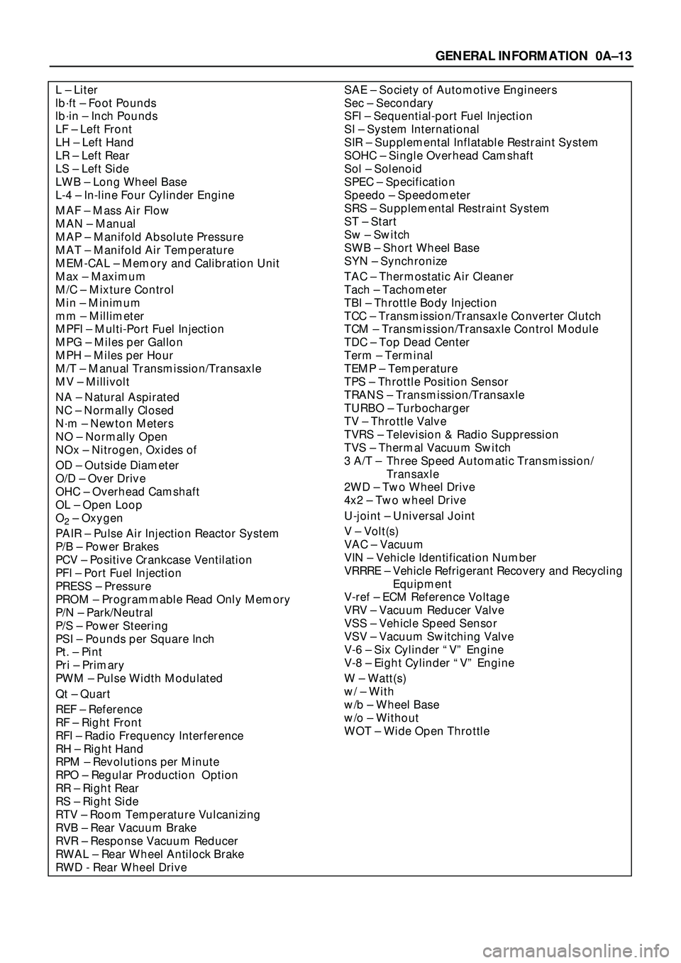
SAE Ð Society of Automotive Engineers
Sec Ð Secondary
SFI Ð Sequential-port Fuel Injection
SI Ð System International
SIR Ð Supplemental Inflatable Restraint System
SOHC Ð Single Overhead Camshaft
Sol Ð Solenoid
SPEC Ð Specification
Speedo Ð Speedometer
SRS Ð Supplemental Restraint System
ST Ð Start
Sw Ð Switch
SWB Ð Short Wheel Base
SYN Ð Synchronize
TAC Ð Thermostatic Air Cleaner
Tach Ð Tachometer
TBI Ð Throttle Body Injection
TCC Ð Transmission/Transaxle Converter Clutch
TCM Ð Transmission/Transaxle Control Module
TDC Ð Top Dead Center
Term Ð Terminal
TEMP Ð Temperature
TPS Ð Throttle Position Sensor
TRANS Ð Transmission/Transaxle
TURBO Ð Turbocharger
TV Ð Throttle Valve
TVRS Ð Television & Radio Suppression
TVS Ð Thermal Vacuum Switch
3 A/T Ð Three Speed Automatic Transmission/
Transaxle
2WD Ð Two Wheel Drive
4x2 Ð Two wheel Drive
U-joint Ð Universal Joint
V Ð Volt(s)
VAC Ð Vacuum
VIN Ð Vehicle Identification Number
VRRRE Ð Vehicle Refrigerant Recovery and Recycling
Equipment
V-ref Ð ECM Reference Voltage
VRV Ð Vacuum Reducer Valve
VSS Ð Vehicle Speed Sensor
VSV Ð Vacuum Switching Valve
V-6 Ð Six Cylinder ÒVÓ Engine
V-8 Ð Eight Cylinder ÒVÓ Engine
W Ð Watt(s)
w/ Ð With
w/b Ð Wheel Base
w/o Ð Without
WOT Ð Wide Open ThrottleL Ð Liter
lbáft Ð Foot Pounds
lbáin Ð Inch Pounds
LF Ð Left Front
LH Ð Left Hand
LR Ð Left Rear
LS Ð Left Side
LWB Ð Long Wheel Base
L-4 Ð In-line Four Cylinder Engine
MAF Ð Mass Air Flow
MAN Ð Manual
MAP Ð Manifold Absolute Pressure
MAT Ð Manifold Air Temperature
MEM-CAL Ð Memory and Calibration Unit
Max Ð Maximum
M/C Ð Mixture Control
Min Ð Minimum
mm Ð Millimeter
MPFI Ð Multi-Port Fuel Injection
MPG Ð Miles per Gallon
MPH Ð Miles per Hour
M/T Ð Manual Transmission/Transaxle
MV Ð Millivolt
NA Ð Natural Aspirated
NC Ð Normally Closed
Nám Ð Newton Meters
NO Ð Normally Open
NOx Ð Nitrogen, Oxides of
OD Ð Outside Diameter
O/D Ð Over Drive
OHC Ð Overhead Camshaft
OL Ð Open Loop
O
2Ð Oxygen
PAIR Ð Pulse Air Injection Reactor System
P/B Ð Power Brakes
PCV Ð Positive Crankcase Ventilation
PFI Ð Port Fuel Injection
PRESS Ð Pressure
PROM Ð Programmable Read Only Memory
P/N Ð Park/Neutral
P/S Ð Power Steering
PSI Ð Pounds per Square Inch
Pt. Ð Pint
Pri Ð Primary
PWM Ð Pulse Width Modulated
Qt Ð Quart
REF Ð Reference
RF Ð Right Front
RFI Ð Radio Frequency Interference
RH Ð Right Hand
RPM Ð Revolutions per Minute
RPO Ð Regular Production Option
RR Ð Right Rear
RS Ð Right Side
RTV Ð Room Temperature Vulcanizing
RVB Ð Rear Vacuum Brake
RVR Ð Response Vacuum Reducer
RWAL Ð Rear Wheel Antilock Brake
RWD - Rear Wheel Drive
GENERAL INFORMATION 0AÐ13
Page 30 of 3573
MAINTENANCE AND LUBRICATION 0BÐ3
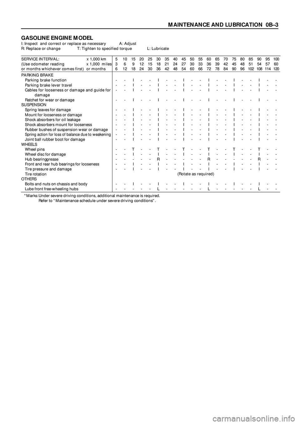
GASOLINE ENGINE MODELI: Inspect and correct or replace as necessary A: Adjust
R: Replace or change T: Tighten to specified torque L: Lubricate
SERVICE INTERVAL: x 1,000 km
(Use odometer reading x 1,000 miles
or months whichever comes first) or months5
3
610
6
1215
9
1820
12
2425
15
3030
18
3635
21
4240
24
4845
27
5450
30
6055
33
6660
36
7265
39
7870
42
8475
45
9080
48
9685
51
10290
54
10895
57
114100
60
120
PARKING BRAKE
Parking brake function
Parking brake lever travel
Cables for looseness or damage and guide for
damage
Ratchet for wear or damage
SUSPENSION
Spring leaves for damage
Mount for looseness or damage
Shock absorbers for oil leakage
Shock absorbers mount for looseness
Rubber bushes of suspension wear or damage
Spring action for loss of balance due to weakeningJoint ball rubber boot for damage
WHEELS
Wheel pins
Wheel disc for damage
Hub bearing grease
Front and rear hub bearings for looseness
Tire pressure and damage
Tire rotation
OTHERS
Bolts and nuts on chassis and body
Lube front free-wheeling hubs-
-
-
-
-
-
-
-
-
-
-
-
-
-
-
-
-
--
-
-
-
-
-
-
-
-
-
-
-
-
-
-
-
-
-I
I
I
I
I
I
I
I
I
I
I
T
I
-
I
I
I
--
-
-
-
-
-
-
-
-
-
-
-
-
-
-
-
-
--
-
-
-
-
-
-
-
-
-
-
-
-
-
-
-
-
-I
I
I
I
I
I
I
I
I
I
I
T
I
R
I
I
I
L-
-
-
-
-
-
-
-
-
-
-
-
-
-
-
-
-
--
-
-
-
-
-
-
-
-
-
-
-
-
-
-
-
-
-I
I
I
I
I
I
I
I
I
I
I
T
I
-
I
I
I
--
-
-
-
-
-
-
-
-
-
-
-
-
-
-
-
-
--
-
-
-
-
-
-
-
-
-
-
-
-
-
-
-
-
-I
I
I
I
I
I
I
I
I
I
I
T
I
R
I
I
I
L-
-
-
-
-
-
-
-
-
-
-
-
-
-
-
-
-
--
-
-
-
-
-
-
-
-
-
-
-
-
-
-
-
-
-I
I
I
I
I
I
I
I
I
I
I
T
I
-
I
I
I
--
-
-
-
-
-
-
-
-
-
-
-
-
-
-
-
-
--
-
-
-
-
-
-
-
-
-
-
-
-
-
-
-
-
-I
I
I
I
I
I
I
I
I
I
I
T
I
R
I
I
I
L-
-
-
-
-
-
-
-
-
-
-
-
-
-
-
-
-
--
-
-
-
-
-
-
-
-
-
-
-
-
-
-
-
-
-
(Rotate as required)
*Marks: Under severe driving conditions, additional maintenance is required.
Refer to “Maintenance schedule under severe driving conditions”.
Page 32 of 3573
MAINTENANCE AND LUBRICATION 0BÐ5
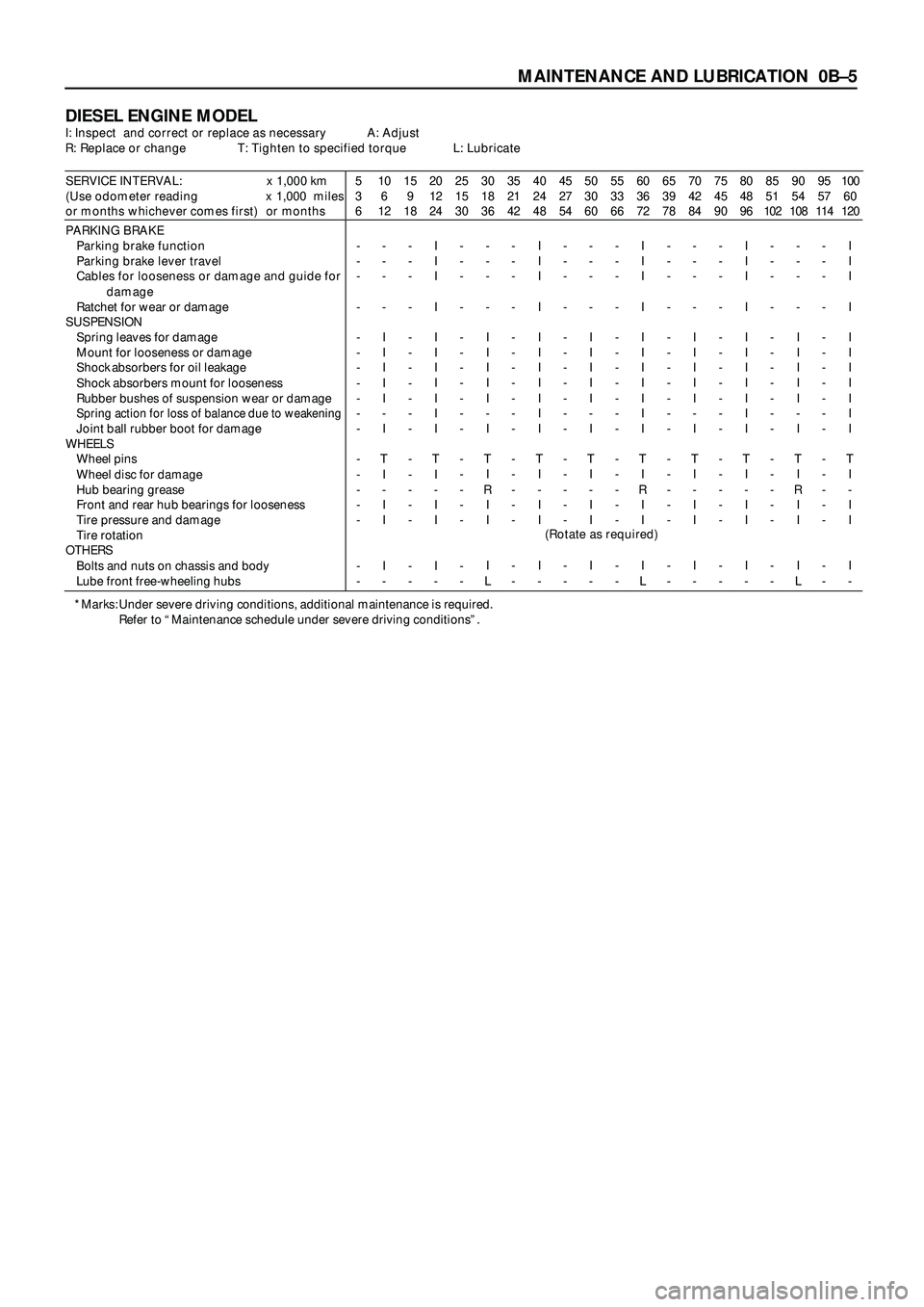
DIESEL ENGINE MODELI: Inspect and correct or replace as necessary A: Adjust
R: Replace or change T: Tighten to specified torque L: Lubricate
SERVICE INTERVAL: x 1,000 km
(Use odometer reading x 1,000 miles
or months whichever comes first) or months5
3
610
6
1215
9
1820
12
2425
15
3030
18
3635
21
4240
24
4845
27
5450
30
6055
33
6660
36
7265
39
7870
42
8475
45
9080
48
9685
51
10290
54
10895
57
114100
60
120
PARKING BRAKE
Parking brake function
Parking brake lever travel
Cables for looseness or damage and guide for
damage
Ratchet for wear or damage
SUSPENSION
Spring leaves for damage
Mount for looseness or damage
Shock absorbers for oil leakage
Shock absorbers mount for looseness
Rubber bushes of suspension wear or damage
Spring action for loss of balance due to weakeningJoint ball rubber boot for damage
WHEELS
Wheel pins
Wheel disc for damage
Hub bearing grease
Front and rear hub bearings for looseness
Tire pressure and damage
Tire rotation
OTHERS
Bolts and nuts on chassis and body
Lube front free-wheeling hubs-
-
-
-
-
-
-
-
-
-
-
-
-
-
-
-
-
--
-
-
-
I
I
I
I
I
-
I
T
I
-
I
I
I
--
-
-
-
-
-
-
-
-
-
-
-
-
-
-
-
-
-I
I
I
I
I
I
I
I
I
I
I
T
I
-
I
I
I
--
-
-
-
-
-
-
-
-
-
-
-
-
-
-
-
-
--
-
-
-
I
I
I
I
I
-
I
T
I
R
I
I
I
L-
-
-
-
-
-
-
-
-
-
-
-
-
-
-
-
-
-I
I
I
I
I
I
I
I
I
I
I
T
I
-
I
I
I
--
-
-
-
-
-
-
-
-
-
-
-
-
-
-
-
-
--
-
-
-
I
I
I
I
I
-
I
T
I
-
I
I
I
--
-
-
-
-
-
-
-
-
-
-
-
-
-
-
-
-
-I
I
I
I
I
I
I
I
I
I
I
T
I
R
I
I
I
L-
-
-
-
-
-
-
-
-
-
-
-
-
-
-
-
-
--
-
-
-
I
I
I
I
I
-
I
T
I
-
I
I
I
--
-
-
-
-
-
-
-
-
-
-
-
-
-
-
-
-
-I
I
I
I
I
I
I
I
I
I
I
T
I
-
I
I
I
--
-
-
-
-
-
-
-
-
-
-
-
-
-
-
-
-
--
-
-
-
I
I
I
I
I
-
I
T
I
R
I
I
I
L-
-
-
-
-
-
-
-
-
-
-
-
-
-
-
-
-
-I
I
I
I
I
I
I
I
I
I
I
T
I
-
I
I
I
-
(Rotate as required)
*Marks: Under severe driving conditions, additional maintenance is required.
Refer to “Maintenance schedule under severe driving conditions”.
Page 126 of 3573
HEATING AND VENTILATION 1A Ð 31
REMOVAL
Preparation:
Disconnect the battery ground cable
1. Instrument panel assembly
Refer to Section 10 ÒBODYÓ for ÒINSTRUMENT
PANEL ASSEMBLYÓ removal procedure.
2. Instrument panel center bracket
Refer to Section 10 ÒCROSS BEAM ASSEMBLYÓ
removal procedure.
3. Rear heater duct
4. Ceramic heater
1) Disconnect the connector and remove the heater
fixing screw and heater harness fixing clamps.
2) Pull the ceramic heater out from heater unit.
4a. Full hot switch
Disconnect the switch connector and remove the
switch fixing screw and switch harness fixing clamp.
INSTALLATION
To install, follow the removal steps in the reverse order,
noting the following points.
1. The installation should be made with care so that
there is continuity between the switch side connector
terminals when the knob is set to the ÒFull HotÓ
position.
2. Be sure to handle the EGR and the ABS control unit
with care to avoid the disengagement of connectors.
Page 145 of 3573
AIR CONDITIONING 1B Ð 19
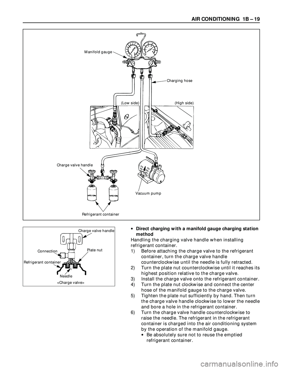
·Direct charging with a manifold gauge charging station
method
Handling the charging valve handle when installing
refrigerant container.
1) Before attaching the charge valve to the refrigerant
container, turn the charge valve handle
counterclockwise until the needle is fully retracted.
2) Turn the plate nut counterclockwise until it reaches its
highest position relative to the charge valve.
3) Install the charge valve onto the refrigerant container.
4) Turn the plate nut clockwise and connect the center
hose of the manifold gauge to the charge valve.
5) Tighten the plate nut sufficiently by hand. Then turn
the charge valve handle clockwise to lower the needle
and bore a hole in the refrigerant container.
6) Turn the charge valve handle counterclockwise to
raise the needle. The refrigerant in the refrigerant
container is charged into the air conditioning system
by the operation of the manifold gauge.
·Be absolutely sure not to reuse the emptied
refrigerant container.Charge valve handle
Plate nut
Needle Connection
Refrigerant container
Charging hose Manifold gauge
Vacuum pump
Refrigerant container
Charge valve handle
(Low side) (High side)
Page 146 of 3573

1B Ð 20 AIR CONDITIONING
1) Make sure the evacuation process is correctly
completed.
2) Connect the center-hose of the manifold gauge to the
refrigerant container.
·Turn the charge valve handle counterclockwise to
purge the charging line and purge any air existing
in the center-hose of the manifold gauge.
3) Open the low-pressure hand valve and charge the
refrigerant about 200 g(0.44 lbs.).
·Make sure the high-pressure hand valve is closed.
·Avoid charging the refrigerant by turning the
refrigerant container upside down.
4) Close the low-pressure hand valve of the manifold
gauge.
·Check to ensure that the degree of pressure does
not charge.
5) Check the refrigerant leaks by using a HFC-134a leak
detector.
·If a leak occurs, repair the leak connection, and
start all over again from the first step of
evacuation.
6) If no leaks are found, open the low-pressure hand
valve of the manifold gauge.Then continue charging
refrigerant to the system.
·When charging the system becomes difficult:
(1) Run the engine at Idling and close the all
vehicle doors.
(2) A/C switch is ÒONÓ.
(3) Set the fan control knob (fan switch) to its
highest position.
WARNING
BE ABSOLUTELY SURE NOT TO OPEN THE HIGH-
PRESSURE HAND VALVE. SHOULD THE HIGH-
PRESSURE HAND VALVE BE OPENED, THE HIGH-
PRESSURE REFRIGERANT GAS WOULD FLOW
BACKWARD, AND THIS MAY CAUSE THE
REFRIGERANT CONTAINER TO BURST.
7) When the refrigerant container is emptied, use the
following procedure to replace it with a new
refrigerant container.
(1) Close the low pressure hand valve.
(2) Raise the needle upward and remove the charge
valve.
(3) Reinstall the charge valve to the new refrigerant
container.
(4) Purge any air existing in the center hose of the
manifold gauge.