Page 2568 of 3573

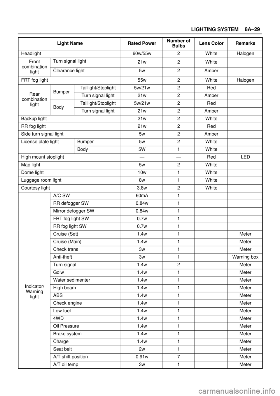
LIGHTING SYSTEM8A–29
Light NameRated PowerNumber of
BulbsLens ColorRemarks
Headlight60w/55w2WhiteHalogen
FrontTurn signal light21w2Whitecombination
lightClearance light5w2Amber
FRT fog light55w2WhiteHalogen
Taillight/Stoplight5w/21w2Red
RearBumperTurn signal light21w2Ambercombination
lightTaillight/Stoplight5w/21w2RedBodyTurn signal light21w2Amber
Backup light21w2White
RR fog light21w2Red
Side turn signal light5w2Amber
License plate lightBumper5w2White
Body5W1White
High mount stoplight——RedLED
Map light5w2White
Dome light10w1White
Luggage room light8w1White
Courtesy light3.8w2White
A/C SW60mA1
RR defogger SW0.84w1
Mirror defogger SW0.84w1
FRT fog light SW0.7w1
RR fog light SW0.7w1
Cruise (Set)1.4w1Meter
Cruise (Main)1.4w1Meter
Check trans3w1Meter
Anti-theft3w1Warning box
Turn signal1.4w2Meter
Golw1.4w1Meter
Water sedimenter1.4w1Meter
Indicator/High beam1.4w1MeterWarning
lightABS1.4w1Meter
Check engine1.4w1Meter
Low fuel1.4w1Meter
4WD1.4w1Meter
Oil Pressure1.4w1Meter
Brake system1.4w1Meter
Charge1.4w1Meter
Seat belt2w1Meter
A/T shift position0.91w7Meter
A/T oil temp3w1Meter
Page 2629 of 3573

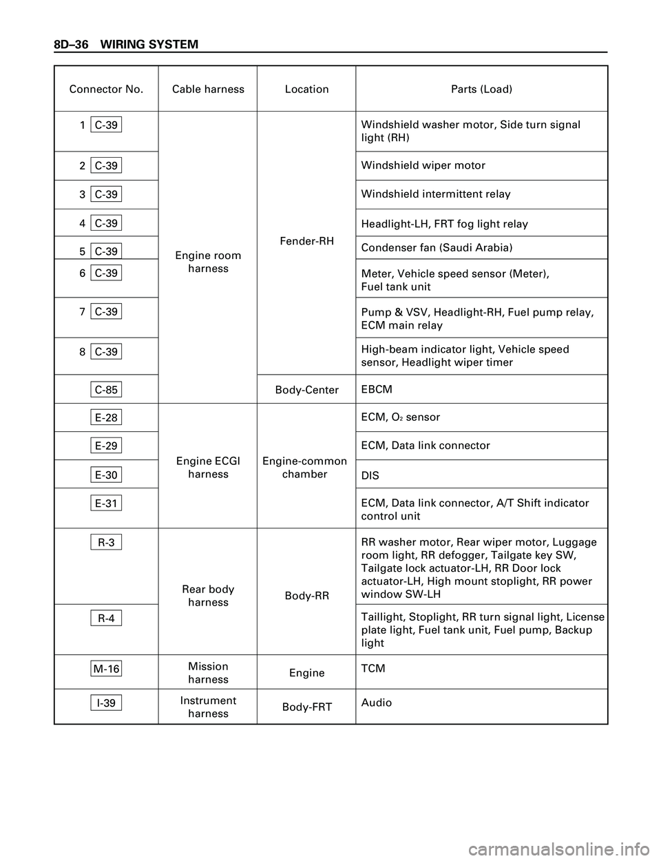
8DÐ36 WIRING SYSTEM
Connector No. Cable harness Location Parts (Load)
C-39
Windshield washer motor, Side turn signal
light (RH)1
C-39
Windshield wiper motor2
C-39
Headlight-LH, FRT fog light relay4
C-39Meter, Vehicle speed sensor (Meter),
Fuel tank unit 6
Engine room
harnessFender-RH
E-28
ECM, O2 sensor
E-29ECM, Data link connector
Engine ECGI
harnessEngine-common
chamber
R-3
RR washer motor, Rear wiper motor, Luggage
room light, RR defogger, Tailgate key SW,
Tailgate lock actuator-LH, RR Door lock
actuator-LH, High mount stoplight, RR power
window SW-LH
R-4Taillight, Stoplight, RR turn signal light, License
plate light, Fuel tank unit, Fuel pump, Backup
light Rear body
harnessBody-RR
E-30
E-31ECM, Data link connector, A/T Shift indicator
control unit DIS
C-39Condenser fan (Saudi Arabia)
5
C-39Windshield intermittent relay3
M-16
TCMMission
harnessEngine
C-39Pump & VSV, Headlight-RH, Fuel pump relay,
ECM main relay 7
C-39High-beam indicator light, Vehicle speed
sensor, Headlight wiper timer 8
I-39
AudioInstrument
harnessBody-FRT C-85
EBCMBody-Center
Page 2633 of 3573
8DÐ40 WIRING SYSTEM
Connector No. Cable harness Location Parts (Load)
C-39
Windshield washer motor, Headlight-LH,
Side turn signal light (RH)1
C-39
Windshield wiper motor2
C-39
FRT fog light relay, Charge relay,
Headlight-LH4
C-39Meter, Vehicle speed sensor (Meter),
Fuel tank unit 6
Engine room
harnessFender-RH
R-3
RR washer motor, Rear wiper motor, Luggage
room light, RR defogger, Tailgate key SW,
Tailgate lock actuator-LH, RR door lock
actuator-LH, RR power window SW-LH, High
mount stoplight
R-4Taillight, Stoplight, RR turn signal light,
License plate light, Backup light Rear body
harnessBody-RR
C-39Condenser fan (Saudi Arabia)
5C-39
Windshield intermittent relay3
C-39Headlight-RH, Tacho sensor 7
C-39Headlight wiper timer, High-beam indicator
light, Vehicle speed sensor 8
I-39
Audio Instrument
harnessBody-FRT C-85
EBCMBody-FRT
Page 2720 of 3573
WIRING SYSTEM 8DÐ127
Headlight and Fog Light
General Description
The circuit consists of the headlight, FRT fog light,
lighting SW, dimmerápassing SW, FRT fog light SW,
high beam indicator, tail relay, lighting relay, FRT
fog light relay and dimmer relay (LHD).
When the lighting SW is turned on by setting it at
headlight position, the lighting relay is activated to
turn on the headlight. The optical axis of the
headlight can be turned up or down by operating the
dimmer SW while the headlight is on.
The passing SW is independent of the lighting SW,
and the optical axis of the passing light can beturned up only while the switch lever is pulled up
and held in this state.
FRT fog lights turn on when the lighting SW is at
clearance light or headlight position.
Page 2722 of 3573
WIRING SYSTEM 8DÐ129
Circuit Diagram (RHD)-2
A
B
C
C-24
FOG
LIGHT
-LHHEAD
LIGHT
-LHHEAD
LIGHT
-RH
LIGHTING
SW
DIMMER·PASSING
SW
(COMBINATION
SW)
1.25
V
1.25
V
0.5
B0.5
B
FOG
LIGHT
-RHHIGH
BEAM
INIDI-
CATOR
(METER)
1
2
C-29
0.85
R/L
0.85
R/Y 0.85
R/Y0.85
R/L
1.25
R/Y
1.25
R/Y
1.25
R/Y0.3
V/R
0.5
B 0.3
V/R
1.25
B
BODY-RH LOW HIGHPASS
H-1510
H-1316
H-4113
H-99
H-4116
14
I-10
I-10
1 C-21
212 C-21
13
B-12
15
B-1214 15
C-213
1
2 C-24 C-29
5
C-16
FENDER-LH
D
E
F
0.85
LG/R
0.85
Y
0.85
Y 0.85
Y
0.85
Y1.25
R/Y
C-32
C-32
C-323
B-12
16
B-12
7
B-19
1
B-12
B-12
D08RW609
Page 2725 of 3573
8DÐ132 WIRING SYSTEM
AC-24
FOG
LIGHT
-LHHEAD
LIGHT
-LH
LIGHTING
SW DIMMER/
PASSING
SW
1.25
V
1.25
V
0.5
B0.5
B
FOG
LIGHT
-RHHIGH
BEAM
INIDI-
CATOR
(METER)
1
2
C-290.5
V/R
0.3
V/R0.5
V/R
0.5
B
1.25
B LOW HIGHPASS
H-1510
15
B-1214 1
2 C-24 C-29
5
C-16
FENDER-LH
1
C-39
4
C-39
4
C-39
8
C-39
10 4
H-16
B
C
G
0.85
Y 0.85
Y
0.85
R/Y 0.85
R/Y
(4JG2) (4JG2)
(4JG2)
(4JG2) 0.85
B0.85
B
0.85
B0.85
B
FENDER-RH FENDER-RH FENDER-RH BODY-LH0.5
B0.5
B 3
C-21H-41
C-211
2
B-12
16
B-12
7
B-19
1
B-12
B-12 C-21
H-4116
13
H-41
HEAD
LIGHT
-RH
7
C-39
D
E
F
0.85
R/G0.85
R/L0.5
R
0.85
B3
C-32
C-321
2
C-32
H-4114
12
H-41110.5
R/Y
0.85
R/Y
0.85
R/L
15
I-10
I-10H-16
14
3
H-411.25
R
D08RW804
Circuit Diagram (LHD)-2
Page 2727 of 3573
8DÐ134 WIRING SYSTEM
Diagnosis
Quick Chart for Check Points
1. Headlight (RHD)
Check point
Trouble modeFuse
F–4
(15A)F–5
(15A)Lighting
relayLighting
SWDimmer•
Passing
SWCable
harness Headlight
bulb
1–1. Both Headlights inoperative
1–2. Headlight on the left (or
right) side inoperative
1–3. Both headlights in
low-beam inoperative
1–4. Headlight low-beam on
the left (or right) side
inoperative
1–5. Both headlights in
high–beam inoperative
1–6. Headlight high-beam on the
left (or right) side
inoperative
1–7. Headlight beam does not
change
LH RH
1–8. Headlights remain on when
the lighting SW is turned off
1–9. Headlights come on with
the lighting SW at the
clearance light position
1–10. Passing lights inoperative
Page 2728 of 3573
WIRING SYSTEM 8DÐ135
Check point
Trouble modeFuse
F–4
(10A)F–5
(10A)Dimmer
relayLighting
SWDimmer•
Passing
SWCable
harness Headlight
bulb
2–1. Both Headlights
inoperative
2–2. Headlight on the
left (or right) side
inoperative
2–3. Both headlights
in low-beam
inoperative
2–4. Headlight low-
beam on the left
(or right)
side inoperative
2–5. Both headlights
in high-beam
inoperative
2–6. Headlight
high-beam on
the left (or right)
side inoperative
2–7. Headlight beam
does not change
Lighting
relayF–6
(10A)F–7
(10A)
2–8. Headlights
remain
on when the
lighting SW is
turned off
2–9. Headlights come
on with the
lighting SW at
the clearance
light position
Diode
2–10. Passing lights
inoperative
LH
RH
2. Headlight (LHD)