1998 ISUZU TROOPER controls
[x] Cancel search: controlsPage 76 of 3573
SERVICE INFORMATION 00 Ð 37
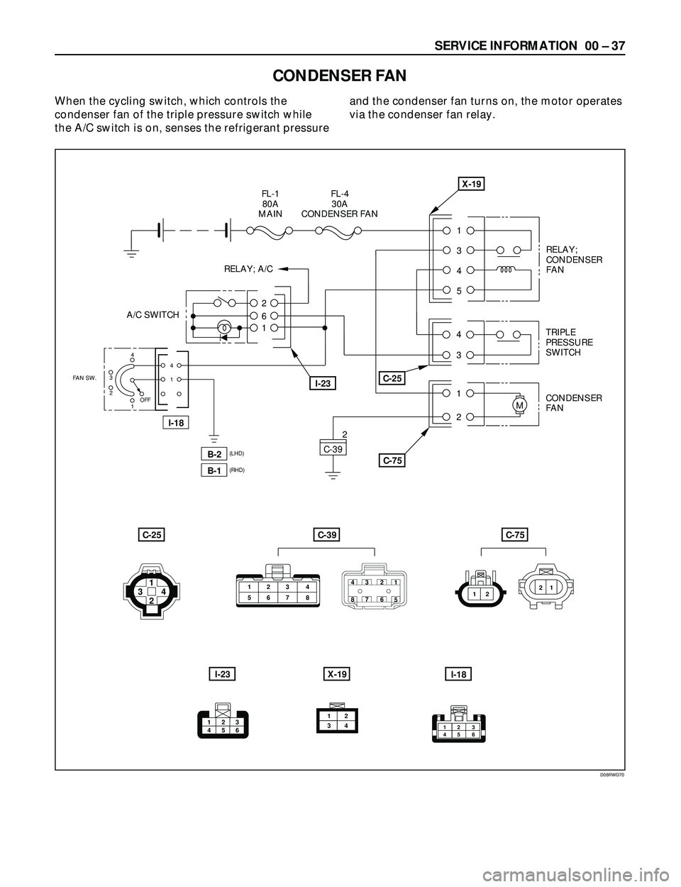
CONDENSER FAN
When the cycling switch, which controls the
condenser fan of the triple pressure switch while
the A/C switch is on, senses the refrigerant pressureand the condenser fan turns on, the motor operates
via the condenser fan relay.
123
45 6
4
13
24
1
FAN SW.
B-2
OFF
I-18
I-18
B-1
(LHD)
(RHD)
X-19
1
3
4
5
RELAY;
CONDENSER
FAN
4TRIPLE
PRESSURE
SWITCH
3
1CONDENSER
FAN
2M
C-75 C-39
C-25
FL-4
30A
CONDENSER FANFL-1
80A
MAIN
2
6
1
I-23
RELAY; A/C
A/C SWITCH
2
C-39C-75C-25
I-23X-19
123 4
567 843
872
61
5
121 21
2 34
213
5 4612
34
D08RWD70
Page 99 of 3573
1A Ð 4 HEATING AND VENTILATION
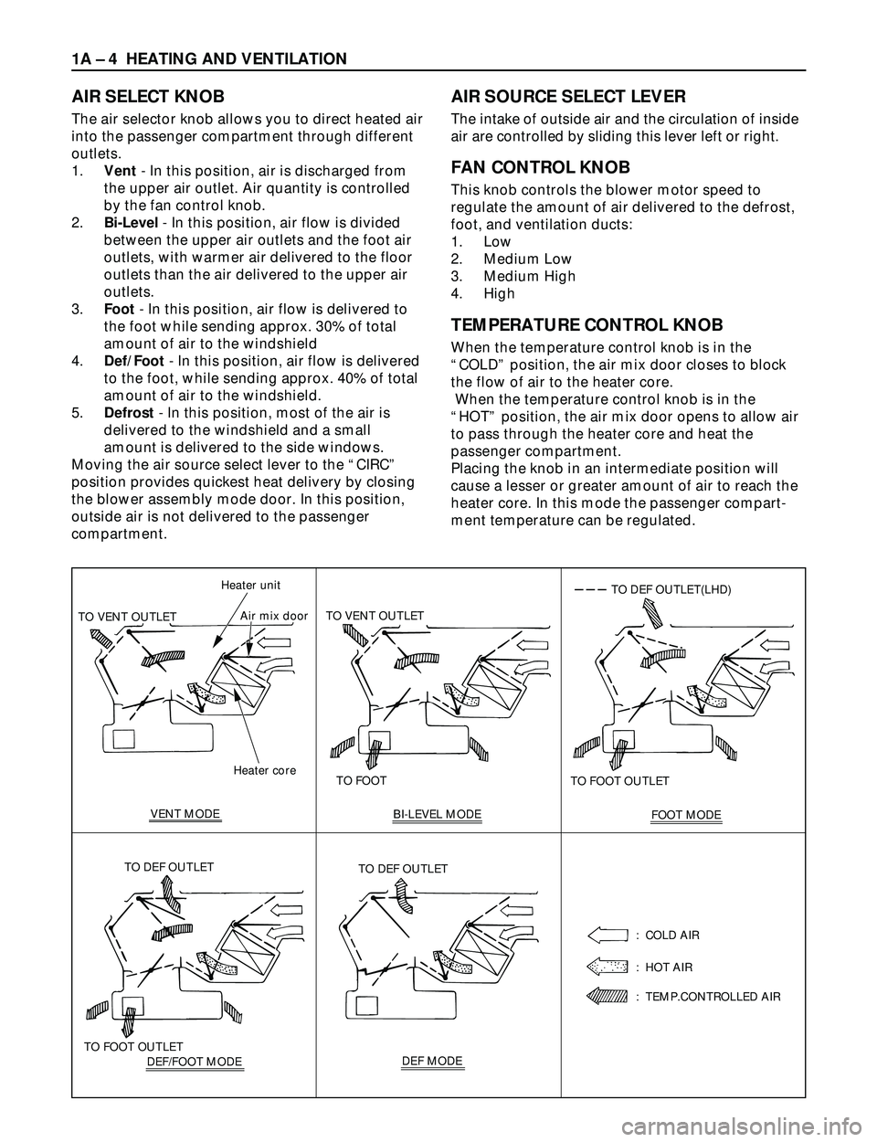
AIR SELECT KNOB
The air selector knob allows you to direct heated air
into the passenger compartment through different
outlets.
1.Vent- In this position, air is discharged from
the upper air outlet. Air quantity is controlled
by the fan control knob.
2.Bi-Level- In this position, air flow is divided
between the upper air outlets and the foot air
outlets, with warmer air delivered to the floor
outlets than the air delivered to the upper air
outlets.
3.Foot- In this position, air flow is delivered to
the foot while sending approx. 30% of total
amount of air to the windshield
4.Def/Foot- In this position, air flow is delivered
to the foot, while sending approx. 40% of total
amount of air to the windshield.
5.Defrost- In this position, most of the air is
delivered to the windshield and a small
amount is delivered to the side windows.
Moving the air source select lever to the ÒCIRCÓ
position provides quickest heat delivery by closing
the blower assembly mode door. In this position,
outside air is not delivered to the passenger
compartment.
AIR SOURCE SELECT LEVER
The intake of outside air and the circulation of inside
air are controlled by sliding this lever left or right.
FAN CONTROL KNOB
This knob controls the blower motor speed to
regulate the amount of air delivered to the defrost,
foot, and ventilation ducts:
1. Low
2. Medium Low
3. Medium High
4. High
TEMPERATURE CONTROL KNOB
When the temperature control knob is in the
ÒCOLDÓ position, the air mix door closes to block
the flow of air to the heater core.
When the temperature control knob is in the
ÒHOTÓ position, the air mix door opens to allow air
to pass through the heater core and heat the
passenger compartment.
Placing the knob in an intermediate position will
cause a lesser or greater amount of air to reach the
heater core. In this mode the passenger compart-
ment temperature can be regulated.
Heater core Heater unit
TO VENT OUTLETAir mix door
VENT MODETO FOOT TO VENT OUTLET
BI-LEVEL MODE
FOOT MODE TO FOOT OUTLET
TO DEF OUTLET(LHD)
DEF/FOOT MODE TO FOOT OUTLETTO DEF OUTLETDEF MODE TO DEF OUTLET
: COLD AIR
: HOT AIR
: TEMP.CONTROLLED AIR
Page 130 of 3573
1B Ð 4 AIR CONDITIONING
The refrigeration cycle includes the following four
processes as the refrigerant changes repeatedly
from liquid to gas and back to liquid while
circulating.
EVAPORATION
The refrigerant is changed from a liquid to a gas
inside the evaporator. The refrigerant mist that
enters the evaporator vaporizes readily. The liquid
refrigerant removes the required quantity of heat
(latent heat of vaporization) from the air around the
evaporator core cooling fins and rapidly vaporizes.
Removing the heat cools the air, which is then
radiated from the fins and lowers the temperature
of the air inside the vehicle.
The refrigerant liquid sent from the expansion valve
and the vaporized refrigerant gas are both present
inside the evaporator and the liquid is converted to
gas.
With this change from liquid to gas, the pressure
inside the evaporator must be kept low enough for
vaporization to occur at a lower temperature.
Because of that, the vaporized refrigerant is sucked
into the compressor.
COMPRESSION
The refrigerant is compressed by the compressor
until it is easily liquefied at normal temperature.
The vaporized refrigerant in the evaporator is
sucked into the compressor. This action maintains
the refrigerant inside the evaporator at a low
pressure so that it can easily vaporize, even at low
temperatures close to 0¡C (32¡F).
Also, the refrigerant sucked into the compressor is
compressed inside the cylinder to increase the
pressure and temperature to values such that the
refrigerant can easily liquefy at normal ambient
temperatures.
CONDENSATION
The refrigerant inside the condenser is cooled by
the outside air and changes from gas to liquid.
The high temperature, high pressure gas coming
from the compressor is cooled and liquefied by the
condenser with outside air and accumulated in the
receiver/drier. The heat radiated to the outside air
by the high temperature, high pressure gas in the
compressor is called heat of condensation. This is
the total quantity of heat (heat of vaporization) the
refrigerant removes from the vehicle interior via the
evaporator and the work (calculated as the quantity
of heat) performed for compression.
EXPANSION
The expansion valve lowers the pressure of the
refrigerant liquid so that it can easily vaporize.
The process of lowering the pressure to encourage
vaporization before the liquefied refrigerant is sent
to the evaporator is called expansion. In addition,
the expansion valve controls the flow rate of the
refrigerant liquid while decreasing the pressure.
That is, the quantity of refrigerant liquid vaporized
inside the evaporator is determined by the quantity
of heat which must be removed at a prescribed
vaporization temperature. It is important that the
quantity of refrigerant be controlled to exactly the
right value.
COMPRESSOR
The compressor performs two main functions:
It compresses low-pressure and low-temperature
refrigerant vapor from the evaporator into high-
pressure and high-temperature refrigerant vapor to
the condenser. And it pumps refrigerant and
refrigerant oil through the A/C system.
6VD1/6VE1 engine on RHD model is equipped with
an invariable capacity five-vane rotary compressor
(DKV-14D Type).
The compressor sucks and compresses refrigerant
by the rotation of the vane installed to the shaft,
and always discharges a fixed amount of refrigerant
independent of the load of refrigerant.
The thermo sensor is installed to the front head of
the compressor to protect it by stopping its
operation when the refrigerant gas is insufficient or
when the temperature is abnormally high.
·OFF ....... 160 ±5¡C (320.0 ±41¡F)
·ON ........ 135 ±5¡C (275.0 ±41¡F)
Diesel Engine models and 6VD1/6VE1 engine on
LHD model are equipped with a swash plate type
compressor
Swash plate compressors have a swash (slanted)
plate mounted on the shaft. When the shaft turns,
the rotation of the swash plate is converted to
reciprocating piston motion which sucks in and
compresses the refrigerant gas.
Shaft seal (Lip type) is installed between the valve
plate and shaft & cylinder head to prevent
refrigerant gas leaks. A specified amount of
compressor oil is contained in the oil pan.
This oil is supplied to the cylinders, bearings, etc.,
by an oil pump which is connected to the swash
plate shaft.
Page 535 of 3573
4B1±2
DRIVE LINE CONTROL SYSTEM (SHIFT ON THE FLY)
Shift on the Fly System (Lever Type)
Outline of Shift on the Fly System
(Lever Type)
The shift on the fly system (Lever type) switches between
2 wheel drive (2WD) and 4 wheel drive (4WD) by driver's
shifting the transfer control lever on the floor.
This system controls below operations.
1. Connecting front wheels to, and disconnecting them
from, the front axles by vacuum actuator.
2. Indicator on instrument panel.
3. 4WD signal to Electronic Hydraulic Control Unit for
brake system (If anti±lock brake system is equipped).
Page 540 of 3573

4B1±7 DRIVE LINE CONTROL SYSTEM (SHIFT ON THE FLY)
Shift on the Fly System (Push Button Type)
Outline of Shift on the Fly System (Push Button Type)
The shift on the fly system switches between 2 wheel
drive (2WD) and 4 wheel drive (4WD) electrically by
driver's pressing the 4WD switch (push button type) on
instrument panel.
This system controls below operations. (Shifting between
ª4Hº and ª4Lº must be performed by transfer control lever
on the floor.)
1. Shifting the transfer front output gear (Connecting to,
and disconnecting from, front propeller shaft by motor
actuator).2. Retrial of shifting the transfer front output gear.
3. Connecting front wheels to, and disconnecting them
from, the front axles by vacuum actuator.
4. Indicator on instrument panel.
5. 4WD out signal to other Electronic Hydraulic Control
Unit (If anti±lock brake system is equipped).
System Diagrams
412RW050
Page 573 of 3573
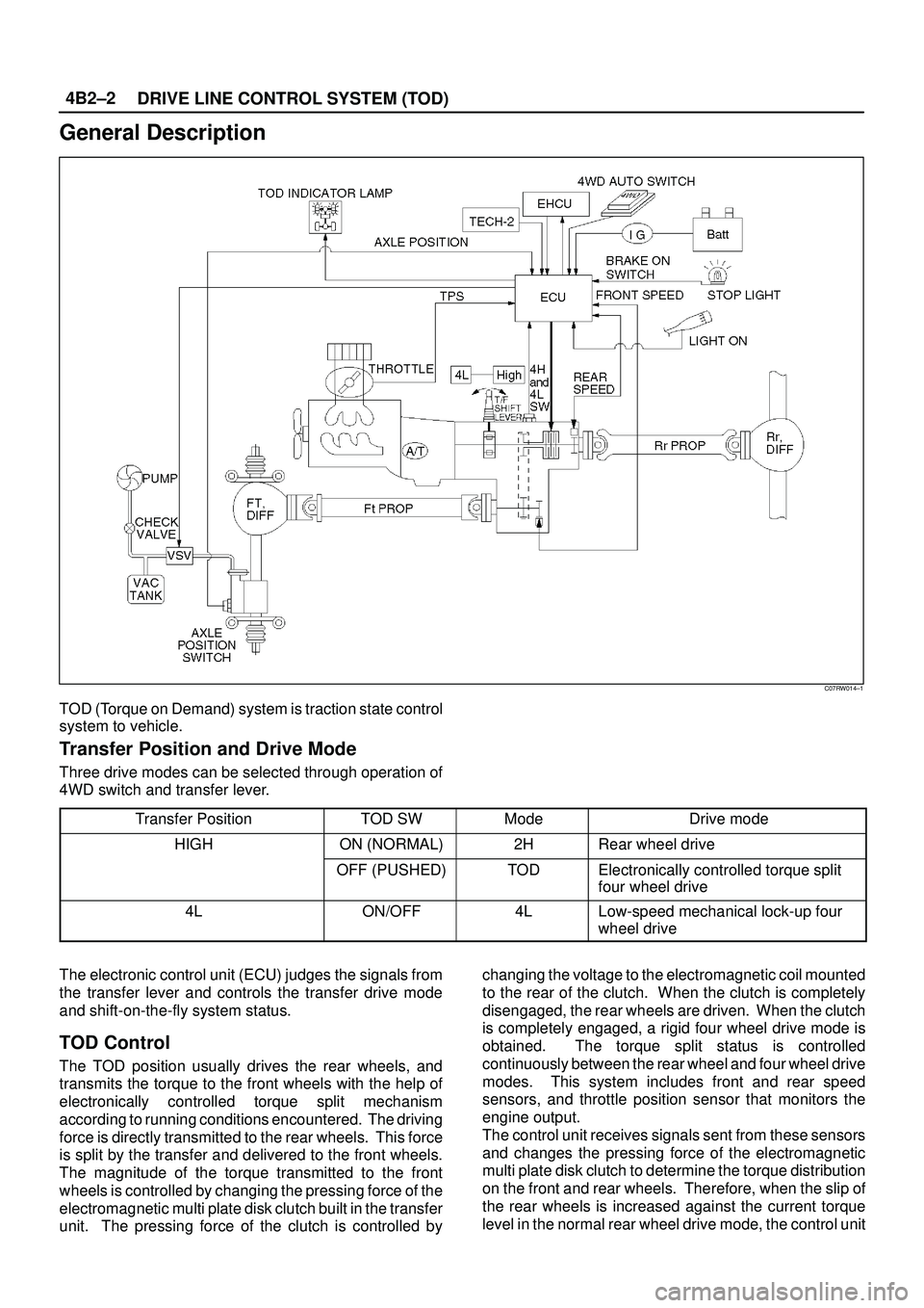
DRIVE LINE CONTROL SYSTEM (TOD) 4B2±2
General Description
C07RW014±1
TOD (Torque on Demand) system is traction state control
system to vehicle.
Transfer Position and Drive Mode
Three drive modes can be selected through operation of
4WD switch and transfer lever.
Transfer Position
TOD SWModeDrive mode
HIGHON (NORMAL)2HRear wheel drive
OFF (PUSHED)TODElectronically controlled torque split
four wheel drive
4LON/OFF4LLow-speed mechanical lock-up four
wheel drive
The electronic control unit (ECU) judges the signals from
the transfer lever and controls the transfer drive mode
and shift-on-the-fly system status.
TOD Control
The TOD position usually drives the rear wheels, and
transmits the torque to the front wheels with the help of
electronically controlled torque split mechanism
according to running conditions encountered. The driving
force is directly transmitted to the rear wheels. This force
is split by the transfer and delivered to the front wheels.
The magnitude of the torque transmitted to the front
wheels is controlled by changing the pressing force of the
electromagnetic multi plate disk clutch built in the transfer
unit. The pressing force of the clutch is controlled bychanging the voltage to the electromagnetic coil mounted
to the rear of the clutch. When the clutch is completely
disengaged, the rear wheels are driven. When the clutch
is completely engaged, a rigid four wheel drive mode is
obtained. The torque split status is controlled
continuously between the rear wheel and four wheel drive
modes. This system includes front and rear speed
sensors, and throttle position sensor that monitors the
engine output.
The control unit receives signals sent from these sensors
and changes the pressing force of the electromagnetic
multi plate disk clutch to determine the torque distribution
on the front and rear wheels. Therefore, when the slip of
the rear wheels is increased against the current torque
level in the normal rear wheel drive mode, the control unit
Page 576 of 3573

4B2±5 DRIVE LINE CONTROL SYSTEM (TOD)
Front and Rear Speed Sensors
The sensors are built in the transfer case, detect the
rotation of rotors directly coupled to the propeller shafts.
Thirty rectangular pulses are output per one rotation of
the propeller shaft.
261RW045
Electromagnetic Coil
Receives the duty signals from the TOD control unit and
controls the pressing force of the clutch pressure cam.
261RW044
Multi Plate Disk Clutch Pack
Transmits the torque determined by the clutch pressing
force to the front propeller shaft via the front drive chain.
262RW029
Mechanical Lock Sleeve
Couples the front and rear propeller shaft mechanically
when the transfer shaft is in the 4L position.
262RW028
Page 814 of 3573

5A±4
BRAKE CONTROL SYSTEM
normal braking when a malfunction has occurred in the
ABS.
The EHCU has a self-diagnosing function which can
indicate faulty circuits during diagnosis.
The EHCU is mounted on the engine compartment front
right side. It consists of a Motor, Plunger Pump, Solenoid
Valves and Check Valve.
On the outside, the relay box containing a motor relay and
a valve relay is installed.
Solenoid Valves: Reduces or holds the caliper fluid
pressure for each front disc brake or both rear disc brakes
according to the signal sent from the EHCU.
Reservoir: Temporarily holds the brake fluid that returns
from the front and rear disc brake caliper so that pressure
of front disc brake caliper can be reduced smoothly.
Plunger Pump: Feeds the brake fluid held in the reservoir
to the master cylinder.
Motor: Drives the pump according to the signal from
EHCU.
Check Valve: Controls the brake fluid flow.
ABS Warning Light
821RW033Vehicles equipped with the Anti-lock Brake System have
an amber ªABSº warning light in the instrument panel.
The ªABSº warning light will illuminate if a malfunction in
the Anti-lock Brake System is detected by the Electronic
Hydraulic Control Unit (EHCU). In case of an electronic
malfunction, the EHCU will turn ªONº the ªABSº warning
light and disable the Anti-lock braking function.
The ªABSº light will turn ªONº for approximately three
seconds after the ignition switch is to the ªONº position.
If the ªABSº light stays ªONº after the ignition switch is the
ªONº position, or comes ªONº and stays ªONº while
driving, the Anti-lock Brake System should be inspected
for a malfunction according to the diagnosis procedure.
Wheel Speed Sensor
It consists of a sensor and a rotor. The sensor is attached
to the knuckle on the front wheels and to the axle shaft
bearing holder on the rear wheels.
The rotor is press-fit in the axle shaft.The flux generated from electrodes magnetized by a
magnet in the sensor varies due to rotation of the rotor,
and the electromagnetic induction generates alternating
voltage in the coil. This voltage draws a ªsine curveº with
the frequency proportional to rotor speed and it allows
detection of wheel speed.
G-Sensor
The G-sensor installed inside the center console detects
the vehicle deceleration speed and sends a signal to the
EHCU. In 4WD operation, all four wheels may be
decelerated in almost the same phase, since all wheels
are connected mechanically.
This tendency is noticeable particularly on roads with low
friction coefficient, and the ABS control is adversely
affected.
The G-sensor judges whether the friction coefficient of
road surface is low or high, and changes the EHCU's
operating system to ensure ABS control.
Normal and Anti-lock Braking
Under normal driving conditions, the Anti-lock Brake
System functions the same as a standard power assisted
brake system. However, with the detection of wheel
lock-up, a slight bump or kick-back will be felt in the brake
pedal. This pedal ªbumpº will be followed by a series of
short pedal pulsations which occurs in rapid succession.
The brake pedal pulsation will continue until there is no
longer a need for the anti-lock function or until the vehicle
is stopped. A slight ticking or popping noise may be heard
during brake applications when the Anti-lock features is
being used.
When the Anti-lock feature is being used, the brake pedal
may rise even as the brakes are being applied. This is
also normal. Maintaining a constant force on the pedal
will provide the shortest stopping distance.
Brake Pedal Travel
Vehicles equipped with the Anti-lock Brake System may
be stopped by applying normal force to the brake pedal.
Although there is no need to push the pedal beyond the
point where it stops or holds the vehicle, by applying more
force the pedal will continue to travel toward the floor.
This extra brake pedal travel is normal.
Acronyms and Abbreviations
Several acronyms and abbreviations are commonly used
throughout this section:
ABS
Anti-lock Brake System
CKT
Circuit
DLC
Data Link Connector
EHCU
Electronic Hydraulic Control Unit
FL
Front Left