1998 ISUZU TROOPER four wheel drive
[x] Cancel search: four wheel drivePage 26 of 3573
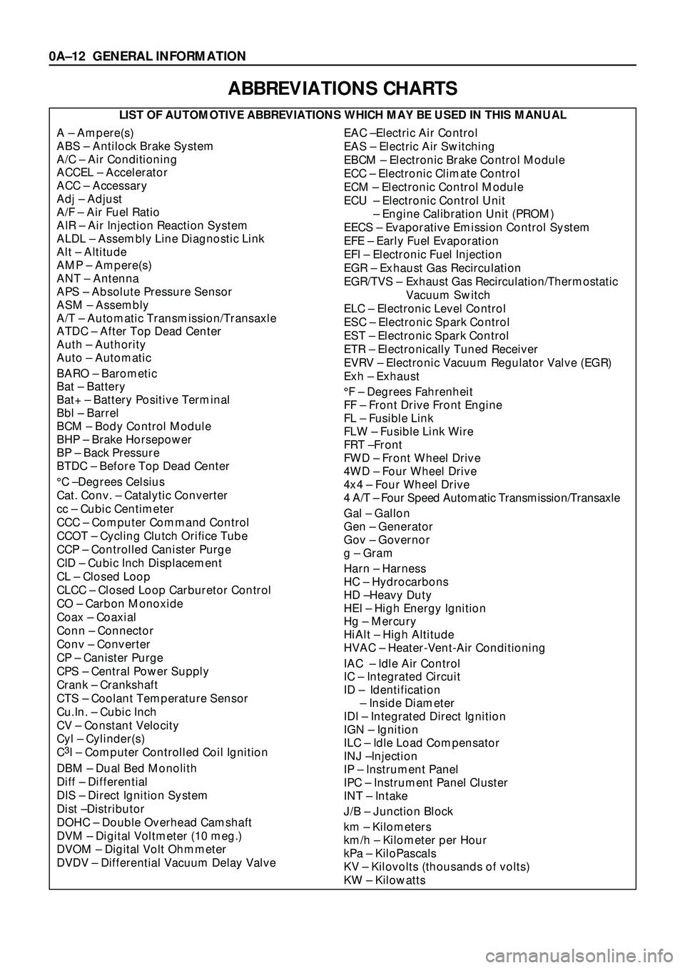
ABBREVIATIONS CHARTS
LIST OF AUTOMOTIVE ABBREVIATIONS WHICH MAY BE USED IN THIS MANUAL
A Ð Ampere(s)
ABS Ð Antilock Brake System
A/C Ð Air Conditioning
ACCEL Ð Accelerator
ACC Ð Accessary
Adj Ð Adjust
A/F Ð Air Fuel Ratio
AIR Ð Air Injection Reaction System
ALDL Ð Assembly Line Diagnostic Link
Alt Ð Altitude
AMP Ð Ampere(s)
ANT Ð Antenna
APS Ð Absolute Pressure Sensor
ASM Ð Assembly
A/T Ð Automatic Transmission/Transaxle
ATDC Ð After Top Dead Center
Auth Ð Authority
Auto Ð Automatic
BARO Ð Barometic
Bat Ð Battery
Bat+ Ð Battery Positive Terminal
Bbl Ð Barrel
BCM Ð Body Control Module
BHP Ð Brake Horsepower
BP Ð Back Pressure
BTDC Ð Before Top Dead Center
¡C ÐDegrees Celsius
Cat. Conv. Ð Catalytic Converter
cc Ð Cubic Centimeter
CCC Ð Computer Command Control
CCOT Ð Cycling Clutch Orifice Tube
CCP Ð Controlled Canister Purge
CID Ð Cubic Inch Displacement
CL Ð Closed Loop
CLCC Ð Closed Loop Carburetor Control
CO Ð Carbon Monoxide
Coax Ð Coaxial
Conn Ð Connector
Conv Ð Converter
CP Ð Canister Purge
CPS Ð Central Power Supply
Crank Ð Crankshaft
CTS Ð Coolant Temperature Sensor
Cu.In. Ð Cubic Inch
CV Ð Constant Velocity
Cyl Ð Cylinder(s)
C
3I Ð Computer Controlled Coil Ignition
DBM Ð Dual Bed Monolith
Diff Ð Differential
DIS Ð Direct Ignition System
Dist ÐDistributor
DOHC Ð Double Overhead Camshaft
DVM Ð Digital Voltmeter (10 meg.)
DVOM Ð Digital Volt Ohmmeter
DVDV Ð Differential Vacuum Delay Valve
EAC ÐElectric Air Control
EAS Ð Electric Air Switching
EBCM Ð Electronic Brake Control Module
ECC Ð Electronic Climate Control
ECM Ð Electronic Control Module
ECU Ð Electronic Control Unit
Ð Engine Calibration Unit (PROM)
EECS Ð Evaporative Emission Control System
EFE Ð Early Fuel Evaporation
EFI Ð Electronic Fuel Injection
EGR Ð Exhaust Gas Recirculation
EGR/TVS Ð Exhaust Gas Recirculation/Thermostatic
Vacuum Switch
ELC Ð Electronic Level Control
ESC Ð Electronic Spark Control
EST Ð Electronic Spark Control
ETR Ð Electronically Tuned Receiver
EVRV Ð Electronic Vacuum Regulator Valve (EGR)
Exh Ð Exhaust
¡F Ð Degrees Fahrenheit
FF Ð Front Drive Front Engine
FL Ð Fusible Link
FLW Ð Fusible Link Wire
FRT ÐFront
FWD Ð Front Wheel Drive
4WD Ð Four Wheel Drive
4x4 Ð Four Wheel Drive
4 A/T Ð Four Speed Automatic Transmission/Transaxle
Gal Ð Gallon
Gen Ð Generator
Gov Ð Governor
g Ð Gram
Harn Ð Harness
HC Ð Hydrocarbons
HD ÐHeavy Duty
HEI Ð High Energy Ignition
Hg Ð Mercury
HiAlt Ð High Altitude
HVAC Ð Heater-Vent-Air Conditioning
IAC Ð Idle Air Control
IC Ð Integrated Circuit
ID Ð Identification
Ð Inside Diameter
IDI Ð Integrated Direct Ignition
IGN Ð Ignition
ILC Ð Idle Load Compensator
INJ ÐInjection
IP Ð Instrument Panel
IPC Ð Instrument Panel Cluster
INT Ð Intake
J/B Ð Junction Block
km Ð Kilometers
km/h Ð Kilometer per Hour
kPa Ð KiloPascals
KV Ð Kilovolts (thousands of volts)
KW Ð Kilowatts
0AÐ12 GENERAL INFORMATION
Page 27 of 3573
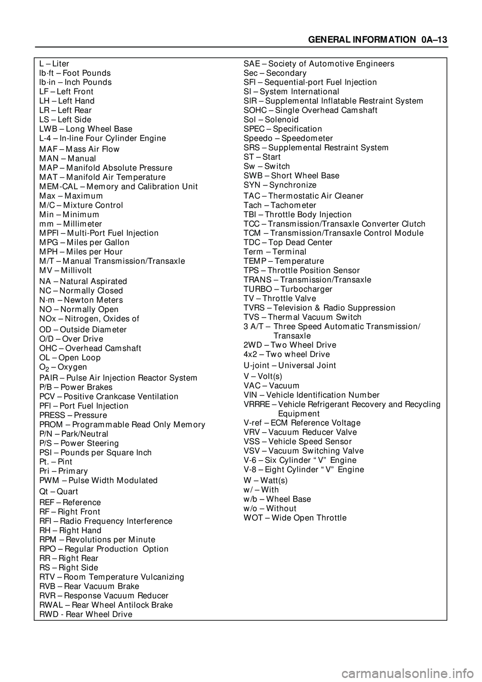
SAE Ð Society of Automotive Engineers
Sec Ð Secondary
SFI Ð Sequential-port Fuel Injection
SI Ð System International
SIR Ð Supplemental Inflatable Restraint System
SOHC Ð Single Overhead Camshaft
Sol Ð Solenoid
SPEC Ð Specification
Speedo Ð Speedometer
SRS Ð Supplemental Restraint System
ST Ð Start
Sw Ð Switch
SWB Ð Short Wheel Base
SYN Ð Synchronize
TAC Ð Thermostatic Air Cleaner
Tach Ð Tachometer
TBI Ð Throttle Body Injection
TCC Ð Transmission/Transaxle Converter Clutch
TCM Ð Transmission/Transaxle Control Module
TDC Ð Top Dead Center
Term Ð Terminal
TEMP Ð Temperature
TPS Ð Throttle Position Sensor
TRANS Ð Transmission/Transaxle
TURBO Ð Turbocharger
TV Ð Throttle Valve
TVRS Ð Television & Radio Suppression
TVS Ð Thermal Vacuum Switch
3 A/T Ð Three Speed Automatic Transmission/
Transaxle
2WD Ð Two Wheel Drive
4x2 Ð Two wheel Drive
U-joint Ð Universal Joint
V Ð Volt(s)
VAC Ð Vacuum
VIN Ð Vehicle Identification Number
VRRRE Ð Vehicle Refrigerant Recovery and Recycling
Equipment
V-ref Ð ECM Reference Voltage
VRV Ð Vacuum Reducer Valve
VSS Ð Vehicle Speed Sensor
VSV Ð Vacuum Switching Valve
V-6 Ð Six Cylinder ÒVÓ Engine
V-8 Ð Eight Cylinder ÒVÓ Engine
W Ð Watt(s)
w/ Ð With
w/b Ð Wheel Base
w/o Ð Without
WOT Ð Wide Open ThrottleL Ð Liter
lbáft Ð Foot Pounds
lbáin Ð Inch Pounds
LF Ð Left Front
LH Ð Left Hand
LR Ð Left Rear
LS Ð Left Side
LWB Ð Long Wheel Base
L-4 Ð In-line Four Cylinder Engine
MAF Ð Mass Air Flow
MAN Ð Manual
MAP Ð Manifold Absolute Pressure
MAT Ð Manifold Air Temperature
MEM-CAL Ð Memory and Calibration Unit
Max Ð Maximum
M/C Ð Mixture Control
Min Ð Minimum
mm Ð Millimeter
MPFI Ð Multi-Port Fuel Injection
MPG Ð Miles per Gallon
MPH Ð Miles per Hour
M/T Ð Manual Transmission/Transaxle
MV Ð Millivolt
NA Ð Natural Aspirated
NC Ð Normally Closed
Nám Ð Newton Meters
NO Ð Normally Open
NOx Ð Nitrogen, Oxides of
OD Ð Outside Diameter
O/D Ð Over Drive
OHC Ð Overhead Camshaft
OL Ð Open Loop
O
2Ð Oxygen
PAIR Ð Pulse Air Injection Reactor System
P/B Ð Power Brakes
PCV Ð Positive Crankcase Ventilation
PFI Ð Port Fuel Injection
PRESS Ð Pressure
PROM Ð Programmable Read Only Memory
P/N Ð Park/Neutral
P/S Ð Power Steering
PSI Ð Pounds per Square Inch
Pt. Ð Pint
Pri Ð Primary
PWM Ð Pulse Width Modulated
Qt Ð Quart
REF Ð Reference
RF Ð Right Front
RFI Ð Radio Frequency Interference
RH Ð Right Hand
RPM Ð Revolutions per Minute
RPO Ð Regular Production Option
RR Ð Right Rear
RS Ð Right Side
RTV Ð Room Temperature Vulcanizing
RVB Ð Rear Vacuum Brake
RVR Ð Response Vacuum Reducer
RWAL Ð Rear Wheel Antilock Brake
RWD - Rear Wheel Drive
GENERAL INFORMATION 0AÐ13
Page 470 of 3573
DIFFERENTIAL (REAR 220mm)
4A2A±3
Diagnosis
Many noises that seem to come from the rear axle
actually originate from other sources such as tires, road
surface, wheel bearings, engine, transmission, muffler, or
body drumming. Investigate to find the source of the
noise before disassembling the rear axle. Rear axles, like
any other mechanical device, are not absolutely quiet but
should be considered quiet unless some abnormal noise
is present.
To make a systematic check for axle noise, observe the
following:
1. Select a level asphalt road to reduce tire noise and
body drumming.
2. Check rear axle lubricant level to assure correct level,
and then drive the vehicle far enough to thoroughly
warm up the rear axle lubricant.
3. Note the speed at which noise occurs. Stop the
vehicle and put the transmission in neutral. Run the
engine speed slowly up and down to determine if the
noise is caused by exhaust, muffler noise, or other
engine conditions.
4. Tire noise changes with different road surfaces; axle
noises do not. Temporarily inflate all tires to 344 kPa
(3.5kg/cm
2, 50 psi) (for test purposes only). This will
change noise caused by tires but will not affect noise
caused by the rear axle.
Rear axle noise usually stops when coasting at
speeds under 48 km/h (30 mph); however, tire noise
continues with a lower tone. Rear axle noise usually
changes when comparing pull and coast, but tire
noise stays about the same.
Distinguish between tire noise and rear axle noise by
noting if the noise changes with various speeds or
sudden acceleration and deceleration. Exhaust and
axle noise vary under these conditions, while tire
noise remains constant and is more pronounced at
speeds of 32 to 48 km/h (20 to 30 mph). Further check
for tire noise by driving the vehicle over smooth
pavements or dirt roads (not gravel) with the tires at
normal pressure. If the noise is caused by tires, it will
change noticeably with changes in road surface.
5. Loose or rough front wheel bearings will cause noise
which may be confused with rear axle noise; however,
front wheel bearing noise does not change when
comparing drive and coast. Light application of the
brake while holding vehicle speed steady will often
cause wheel bearing noise to diminish. Front wheel
bearings may be checked for noise by jacking up the
wheels and spinning them or by shaking the wheels to
determine if bearings are loose.
6. Rear suspension rubber bushings and spring
insulators dampen out rear axle noise when correctly
installed. Check to see that there is no link or rod
loosened or metal±to±metal contact.
7. Make sure that there is no metal±to±metal contact
between the floor and the frame.
After the noise has been determined to be in the axle, the
type of axle noise should be determined, in order to make
any necessary repairs.
Gear Noise
Gear noise (whine) is audible from 32 to 89 km/h (20 to 55
mph) under four driving conditions.
1. Driving under acceleration or heavy pull.
2. Driving under load or under constant speed.
3. When using enough throttle to keep the vehicle from
driving the engine while the vehicle slows down
gradually (engine still pulls slightly).
4. When coasting with the vehicle in gear and the throttle
closed. The gear noise is usually more noticeable
between 48 and 64 km/h (30 and 40 mph) and 80 and
89 km/h (50 and 55 mph).
Bearing Noise
Bad bearings generally produce a rough growl or grating
sound, rather than the whine typical of gear noise.
Bearing noise frequently ªwow±wowsº at bearing rpm,
indicating a bad pinion or rear axle side bearing. This
noise can be confused with rear wheel bearing noise.
Rear Wheel Bearing Noise
Rear wheel bearing noise continues to be heard while
coasting at low speed with transmission in neutral. Noise
may diminish by gentle braking. Jack up the rear wheels,
spin them by hand and listen for noise at the hubs.
Replace any faulty wheel bearings.
Knock At Low Speeds
Low speed knock can be caused by worn universal joints
or a side gear hub counter bore in the cage that is worn
oversize. Inspect and replace universal joints or cage and
side gears as required.
Backlash Clunk
Excessive clunk on acceleration and deceleration can be
caused by a worn rear axle pinion shaft, a worn cage,
excessive clearance between the axle and the side gear
splines, excessive clearance between the side gear hub
and the counterbore in the cage, worn pinion and side
gear teeth, worn thrust washers, or excessive drive pinion
and ring gear backlash. Remove worn parts and replace
as required. Select close±fitting parts when possible.
Adjust pinion and ring gear backlash.
Page 506 of 3573
DIFFERENTIAL (REAR 244mm)
4A2B±3
Diagnosis
Many noises that seem to come from the rear axle
actually originate from other sources such as tires, road
surface, wheel bearings, engine, transmission, muffler, or
body drumming. Investigate to find the source of the
noise before disassembling the rear axle. Rear axles, like
any other mechanical device, are not absolutely quiet but
should be considered quiet unless some abnormal noise
is present.
To make a systematic check for axle noise, observe the
following:
1. Select a level asphalt road to reduce tire noise and
body drumming.
2. Check rear axle lubricant level to assure correct level,
and then drive the vehicle far enough to thoroughly
warm up the rear axle lubricant.
3. Note the speed at which noise occurs. Stop the
vehicle and put the transmission in neutral. Run the
engine speed slowly up and down to determine if the
noise is caused by exhaust, muffler noise, or other
engine conditions.
4. Tire noise changes with different road surfaces; axle
noises do not. Temporarily inflate all tires to 344 kPa
(3.5kg/cm
2, 50 psi) (for test purposes only). This will
change noise caused by tires but will not affect noise
caused by the rear axle.
Rear axle noise usually stops when coasting at
speeds under 48 km/h (30 mph); however, tire noise
continues with a lower tone. Rear axle noise usually
changes when comparing pull and coast, but tire
noise stays about the same.
Distinguish between tire noise and rear axle noise by
noting if the noise changes with various speeds or
sudden acceleration and deceleration. Exhaust and
axle noise vary under these conditions, while tire
noise remains constant and is more pronounced at
speeds of 32 to 48 km/h (20 to 30 mph). Further check
for tire noise by driving the vehicle over smooth
pavements or dirt roads (not gravel) with the tires at
normal pressure. If the noise is caused by tires, it will
change noticeably with changes in road surface.
5. Loose or rough front wheel bearings will cause noise
which may be confused with rear axle noise; however,
front wheel bearing noise does not change when
comparing drive and coast. Light application of the
brake while holding vehicle speed steady will often
cause wheel bearing noise to diminish. Front wheel
bearings may be checked for noise by jacking up the
wheels and spinning them or by shaking the wheels to
determine if bearings are loose.
6. Rear suspension rubber bushings and spring
insulators dampen out rear axle noise when correctly
installed. Check to see that there is no link or rod
loosened or metal±to±metal contact.
7. Make sure that there is no metal±to±metal contact
between the floor and the frame.
After the noise has been determined to be in the axle, the
type of axle noise should be determined, in order to make
any necessary repairs.
Gear Noise
Gear noise (whine) is audible from 32 to 89 km/h (20 to 55
mph) under four driving conditions.
1. Driving under acceleration or heavy pull.
2. Driving under load or under constant speed.
3. When using enough throttle to keep the vehicle from
driving the engine while the vehicle slows down
gradually (engine still pulls slightly).
4. When coasting with the vehicle in gear and the throttle
closed. The gear noise is usually more noticeable
between 48 and 64 km/h (30 and 40 mph) and 80 and
89 km/h (50 and 55 mph).
Bearing Noise
Bad bearings generally produce a rough growl or grating
sound, rather than the whine typical of gear noise.
Bearing noise frequently ªwow±wowsº at bearing rpm,
indicating a bad pinion or rear axle side bearing. This
noise can be confused with rear wheel bearing noise.
Rear Wheel Bearing Noise
Rear wheel bearing noise continues to be heard while
coasting at low speed with transmission in neutral. Noise
may diminish by gentle braking. Jack up the rear wheels,
spin them by hand and listen for noise at the hubs.
Replace any faulty wheel bearings.
Knock At Low Speeds
Low speed knock can be caused by worn universal joints
or a side gear hub counter bore in the cage that is worn
oversize. Inspect and replace universal joints or cage and
side gears as required.
Backlash Clunk
Excessive clunk on acceleration and deceleration can be
caused by a worn rear axle pinion shaft, a worn cage,
excessive clearance between the axle and the side gear
splines, excessive clearance between the side gear hub
and the counterbore in the cage, worn pinion and side
gear teeth, worn thrust washers, or excessive drive pinion
and ring gear backlash. Remove worn parts and replace
as required. Select close±fitting parts when possible.
Adjust pinion and ring gear backlash.
Page 573 of 3573
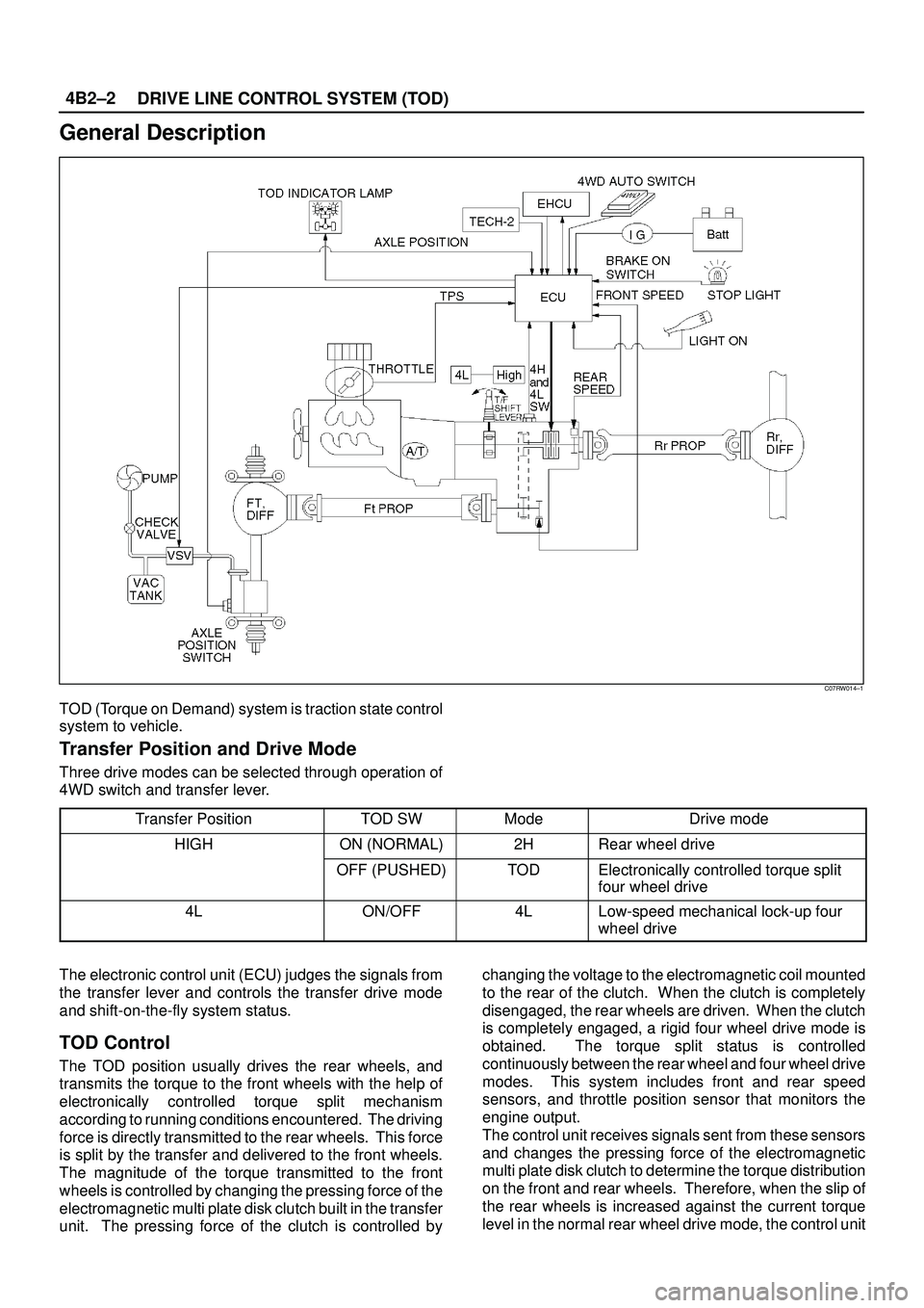
DRIVE LINE CONTROL SYSTEM (TOD) 4B2±2
General Description
C07RW014±1
TOD (Torque on Demand) system is traction state control
system to vehicle.
Transfer Position and Drive Mode
Three drive modes can be selected through operation of
4WD switch and transfer lever.
Transfer Position
TOD SWModeDrive mode
HIGHON (NORMAL)2HRear wheel drive
OFF (PUSHED)TODElectronically controlled torque split
four wheel drive
4LON/OFF4LLow-speed mechanical lock-up four
wheel drive
The electronic control unit (ECU) judges the signals from
the transfer lever and controls the transfer drive mode
and shift-on-the-fly system status.
TOD Control
The TOD position usually drives the rear wheels, and
transmits the torque to the front wheels with the help of
electronically controlled torque split mechanism
according to running conditions encountered. The driving
force is directly transmitted to the rear wheels. This force
is split by the transfer and delivered to the front wheels.
The magnitude of the torque transmitted to the front
wheels is controlled by changing the pressing force of the
electromagnetic multi plate disk clutch built in the transfer
unit. The pressing force of the clutch is controlled bychanging the voltage to the electromagnetic coil mounted
to the rear of the clutch. When the clutch is completely
disengaged, the rear wheels are driven. When the clutch
is completely engaged, a rigid four wheel drive mode is
obtained. The torque split status is controlled
continuously between the rear wheel and four wheel drive
modes. This system includes front and rear speed
sensors, and throttle position sensor that monitors the
engine output.
The control unit receives signals sent from these sensors
and changes the pressing force of the electromagnetic
multi plate disk clutch to determine the torque distribution
on the front and rear wheels. Therefore, when the slip of
the rear wheels is increased against the current torque
level in the normal rear wheel drive mode, the control unit
Page 728 of 3573

TRANSFER CASE (STANDARD TYPE)
4D1±7
A/T, WO/Shift On The Fly, WO/4WD Switch, model
A07RW055
The transfer case is used to provide a means of providing
power flow to the front axle. The transfer case also
provides a means of disconnecting the front axle,
providing better fuel economy and quieter operation when
the vehicle is driven on improved roads where four wheel
drive is not required. In addition, the transfer case
provides an additional gear reduction when placed in low
range, which is useful when difficult off±road conditions
are encountered.
A floor mounted shift lever is used to select the high±low
range. When four wheel drive switch has been turned on,
the four wheel drive indicator light is designed to come on
when the front axle has been engaged.
Page 808 of 3573

4D2±41 TRANSFER CASE (TOD)
Main Data and Specifications
Leading Particulars
TypeTransfer case with low range reduction mechanism
2H Rear wheel drive
TOD Electronically controlled torque split four wheel drive
4L Low-speed mechanical lock-up four wheel drive
Control systemFloor direct control
Gear ratioH1.000
L 2.480
Oil quantity, Lit1.9
OilATF DEXRON)-IIE or ATF DEXRON)-III
Torque Specifications
E04RW012
Page 813 of 3573

5A±3 BRAKE CONTROL SYSTEM
General Description
The Anti-lock Brake System (ABS) works on all four
wheels. A combination of wheel speed sensor and
Electronic Hydraulic Control Unit (EHCU) can determine
when a wheel is about to stop turning and adjust brake
pressure to maintain best braking.This system helps the driver maintain greater control of
the vehicle under heavy braking conditions.
C05RW027
Legend
(1) With P&B Valve Model
(2) With LSPV Model
(3) Electronic Hydraulic Control Unit (EHCU)
(4) Front Wheel Speed Sensor
(5) Rear Wheel Speed Sensor(6) G-Sensor
(7) Proportioning and Bypass (P&B) Valve
(8) Load Sensing Proportioning Valve (LSPV)
(9) Electronic Line
(10) Hydraulic Line
System Components
Electronic Hydraulic Control Unit (EHCU), four Wheel
Speed Sensors, Warning Light, and G-sensor.
Electronic Hydraulic Control Unit (EHCU)
The EHCU consists of ABS control circuits, fault detector,
and a fail-safe. It drives the hydraulic unit according to the
signal from each sensor, cancelling ABS to return to