1998 ISUZU TROOPER stop start
[x] Cancel search: stop startPage 221 of 3573

AIR CONDITIONING 1BÐ95
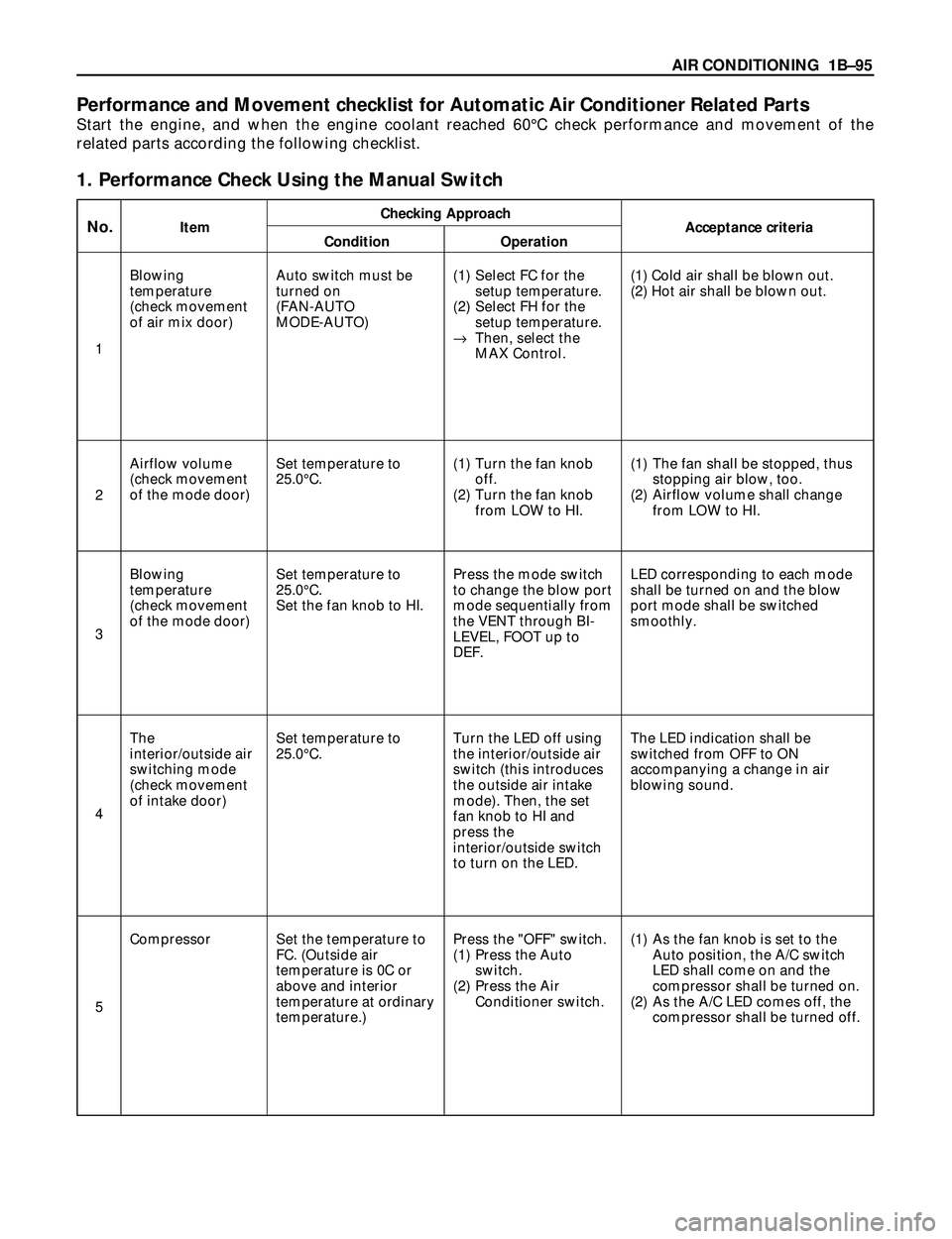
Performance and Movement checklist for Automatic Air Conditioner Related Parts
Start the engine, and when the engine coolant reached 60¡C check performance and movement of the
related parts according the following checklist.
1. Performance Check Using the Manual Switch
Checking ApproachNo.ItemAcceptance criteria
Condition Operation
Blowing
temperature
(check movement
of air mix door)
Airflow volume
(check movement
of the mode door)Set temperature to
25.0¡C.(1) Turn the fan knob
off.
(2) Turn the fan knob
from LOW to HI.(1) The fan shall be stopped, thus
stopping air blow, too.
(2) Airflow volume shall change
from LOW to HI.
Blowing
temperature
(check movement
of the mode door)Set temperature to
25.0¡C.
Set the fan knob to HI.Press the mode switch
to change the blow port
mode sequentially from
the VENT through BI-
LEVEL, FOOT up to
DEF.LED corresponding to each mode
shall be turned on and the blow
port mode shall be switched
smoothly.
The
interior/outside air
switching mode
(check movement
of intake door)Set temperature to
25.0¡C.Turn the LED off using
the interior/outside air
switch (this introduces
the outside air intake
mode). Then, the set
fan knob to HI and
press the
interior/outside switch
to turn on the LED.The LED indication shall be
switched from OFF to ON
accompanying a change in air
blowing sound.
Compressor Set the temperature to
FC. (Outside air
temperature is 0C or
above and interior
temperature at ordinary
temperature.)Press the "OFF" switch.
(1) Press the Auto
switch.
(2) Press the Air
Conditioner switch.(1) As the fan knob is set to the
Auto position, the A/C switch
LED shall come on and the
compressor shall be turned on.
(2) As the A/C LED comes off, the
compressor shall be turned off. Auto switch must be
turned on
(FAN-AUTO
MODE-AUTO)(1) Select FC for the
setup temperature.
(2) Select FH for the
setup temperature.
®Then, select the
MAX Control.(1) Cold air shall be blown out.
(2) Hot air shall be blown out.
1
2
3
4
5
Page 232 of 3573

1BÐ106 AIR CONDITIONING
Chart B: Failure on the Intake Control
NOThe harness is disconnected.
NOFailure on the automatic heater/air
conditioner control unit.
NOFailure on the automatic heater/air
conditioner control unit.
YES YES
YES
Turn on the ignition switch (the engine is
started).
Disconnect the intake actuator connector
(I-49).
Failure on the intake actuator.
Is the intake actuator stopped?
Is conduction provided between the
following chassis harness side connector
terminals?
No.5 and No.11 .
No.6 and No.12 .
No.1 and No.13 .
No.2 and No.14 .
I-33I-49
I-33I-49
I-33I-49
I-33I-49
Is voltage (approximately 5V) present
between the following?
No.12 and the ground.
No.13 and the ground.
No.14 and the ground.
I-33
I-33
I-33
Page 240 of 3573

1BÐ114 AIR CONDITIONING
Chart A: Fan Does Not Rotate At All
NOFailure on the power supply system.
NOFailure on the ground or the harness is
disconnected.
NOReplace the fan motor.
YES
YES YES
Turn on the ignition switch (the engine is
started).
Refer to Charts B and C.
Is the battery voltage present between the
chassis harness side connector terminal
No.2 and the ground?
B-5
Are the chassis harness side connector
terminals No.4 and the ground
(No. ) conducted?
B-1
I-51
Is the battery voltage present between
the chassis harness side connector
terminals No.1 and No.2 ?
B-5B-5
Type of trouble
The fan does not
rotate in any mode
other than MAX HI.The fan does not stop.
Chart BChart CChart D
The fan does not
rotate in the MAX HI
mode.The fan does not
rotate at all.
Chart A
Page 243 of 3573

AIR CONDITIONING 1BÐ117
Chart D: Fan Does Not Stop
NOReplace the power transistor.
NOReplace the relay.
YES
NO YES
Turn on the ignition switch (the engine is
started).
YES
Is the power transistor performance
normal? (Refer to the later section on
"Check Up".)
Is the MAX HI relay performance
normal? (Refer to the later section on
"Check Up".)
Is the battery voltage present between
the chassis harness side connector
terminals No.1 and No.3 ?
I-51I-51
The chassis harness side connector
terminals No.1 and No.2 , or
No.1 and No.1 is short
circuited.
I-50B-5
I-51B-5
Failure on the automatic heater/air
conditioner control unit. Or, the harness
line is short circuited between the chassis
harness side connector terminals No.3
and No.12 .
I-32I-51
Page 261 of 3573

COMPRESSOR OVERHAUL 1D Ð 5
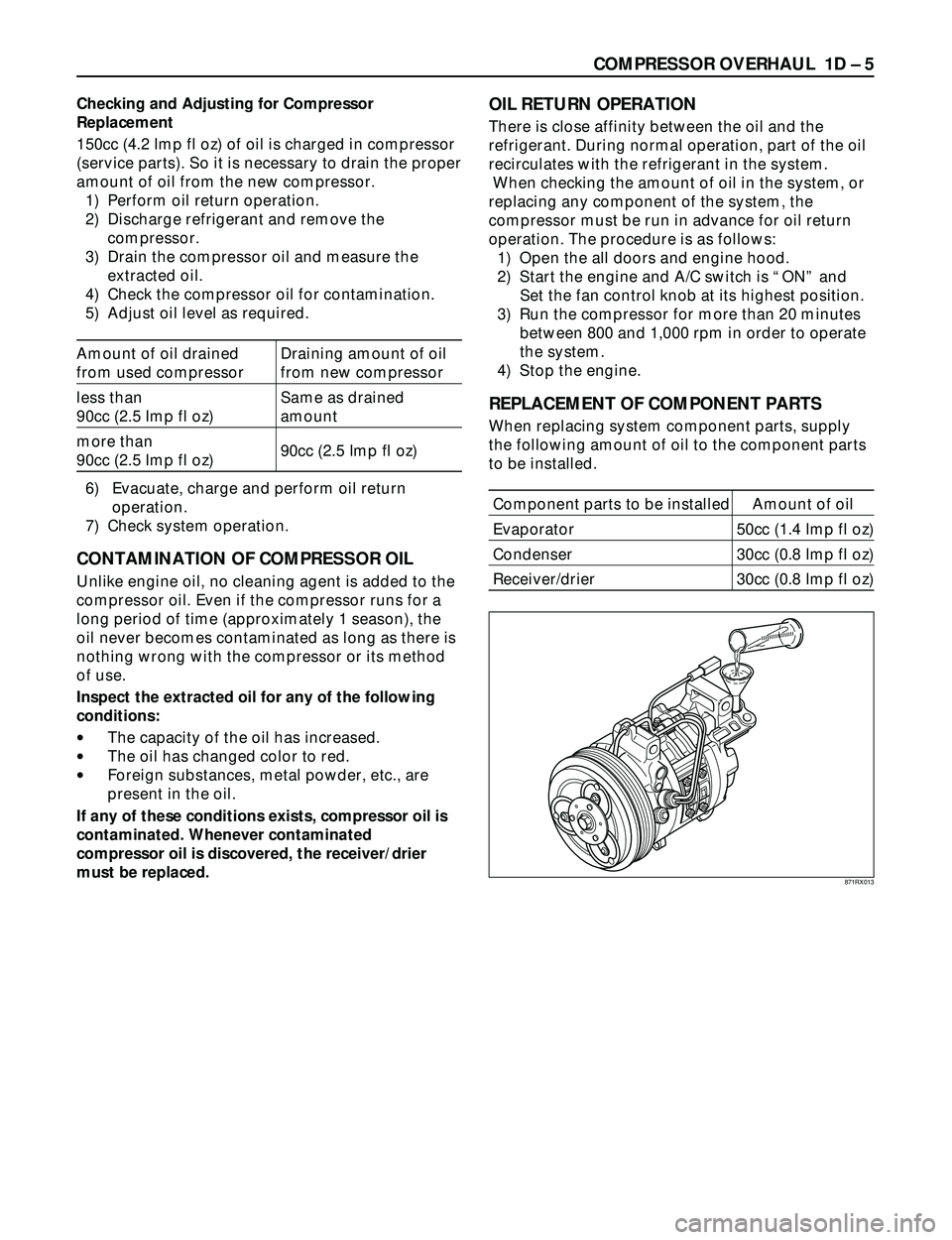
Checking and Adjusting for Compressor
Replacement
150cc (4.2 Imp fl oz) of oil is charged in compressor
(service parts). So it is necessary to drain the proper
amount of oil from the new compressor.
1) Perform oil return operation.
2) Discharge refrigerant and remove the
compressor.
3) Drain the compressor oil and measure the
extracted oil.
4) Check the compressor oil for contamination.
5) Adjust oil level as required.
Amount of oil drained Draining amount of oil
from used compressor from new compressor
less than Same as drained
90cc (2.5 Imp fl oz) amount
more than
90cc (2.5 Imp fl oz)
90cc (2.5 Imp fl oz)
6) Evacuate, charge and perform oil return
operation.
7) Check system operation.
CONTAMINATION OF COMPRESSOR OIL
Unlike engine oil, no cleaning agent is added to the
compressor oil. Even if the compressor runs for a
long period of time (approximately 1 season), the
oil never becomes contaminated as long as there is
nothing wrong with the compressor or its method
of use.
Inspect the extracted oil for any of the following
conditions:
·The capacity of the oil has increased.
·The oil has changed color to red.
·Foreign substances, metal powder, etc., are
present in the oil.
If any of these conditions exists, compressor oil is
contaminated. Whenever contaminated
compressor oil is discovered, the receiver/drier
must be replaced.
OIL RETURN OPERATION
There is close affinity between the oil and the
refrigerant. During normal operation, part of the oil
recirculates with the refrigerant in the system.
When checking the amount of oil in the system, or
replacing any component of the system, the
compressor must be run in advance for oil return
operation. The procedure is as follows:
1) Open the all doors and engine hood.
2) Start the engine and A/C switch is ÒONÓ and
Set the fan control knob at its highest position.
3) Run the compressor for more than 20 minutes
between 800 and 1,000 rpm in order to operate
the system.
4) Stop the engine.
REPLACEMENT OF COMPONENT PARTS
When replacing system component parts, supply
the following amount of oil to the component parts
to be installed.
Component parts to be installed Amount of oil
Evaporator 50cc (1.4 Imp fl oz)
Condenser 30cc (0.8 Imp fl oz)
Receiver/drier 30cc (0.8 Imp fl oz)
871RX013
Page 281 of 3573

COMPRESSOR OVERHAUL 1D Ð 25
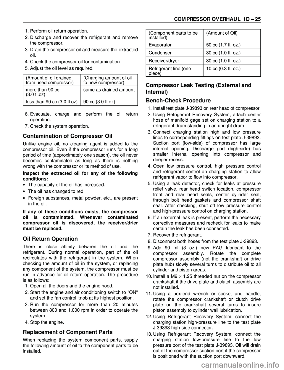
1. Perform oil return operation.
2. Discharge and recover the refrigerant and remove
the compressor.
3. Drain the compressor oil and measure the extracted
oil.
4. Check the compressor oil for contamination.
5. Adjust the oil level as required.
6. Evacuate, charge and perform the oil return
operation.
7. Check the system operation.
Contamination of Compressor Oil
Unlike engine oil, no cleaning agent is added to the
compressor oil. Even if the compressor runs for a long
period of time (approximately one season), the oil never
becomes contaminated as long as there is nothing
wrong with the compressor or its method of use.
Inspect the extracted oil for any of the following
conditions:
·The capacity of the oil has increased.
·The oil has changed to red.
·Foreign substances, metal powder, etc., are present
in the oil.
If any of these conditions exists, the compressor
oil is contaminated. Whenever contaminated
compressor oil is discovered, the receiver/drier
must be replaced.
Oil Return Operation
There is close affinity between the oil and the
refrigerant. During normal operation, part of the oil
recirculates with the refrigerant in the system. When
checking the amount of oil in the system, or replacing
any component of the system, the compressor must be
run in advance for oil return operation. The procedure
is as follows:
1. Open all the doors and the engine hood.
2. Start the engine and air conditioning switch to "ON"
and set the fan control knob at its highest position.
3. Run the compressor for more than 20 minutes
between 800 and 1,000 rpm in order to operate the
system.
4. Stop the engine.
Replacement of Component Parts
When replacing the system component parts, supply
the following amount of oil to the component parts to be
installed.
Compressor Leak Testing (External and
Internal)
Bench-Check Procedure
1. Install test plate J-39893 on rear head of compressor.
2. Using Refrigerant Recovery System, attach center
hose of manifold gage set on charging station to a
refrigerant drum standing in an upright drum.
3. Connect charging station high and low pressure
lines to corresponding fittings on test plate J-39893.
Suction port (low-side) of compressor has large
internal opening. Discharge port (high-side) has
smaller internal opening into compressor and
deeper recess.
4. Open low pressure control, high pressure control
and refrigerant control on charging station to allow
refrigerant vapor to flow into compressor.
5. Using a leak detector, check for leaks at pressure
relief valve, rear head switch location, compressor
front and rear head seals, center cylinder seal,
through bolt head gaskets and compressor shaft
seal. After checking, shut off low pressure control
and high-pressure control on charging station.
6. If an external leak is present, perform the necessary
corrective measures and recheck for leaks to make
certain the leak has been connected.
7. Recover the refrigerant.
8. Disconnect both hoses from the test plate J-39893.
9. Add 90 ml (3 oz.) new PAG lubricant to the
compressor assembly. Rotate the complete
compressor assembly (not the crankshaft or drive
plate hub) slowly several turns to distribute oil to all
cylinder and piston areas.
10. Install a M9 ´1.25 threaded nut on the compressor
crankshaft if the drive plate and clutch assembly are
not installed.
11. Using a box-end wrench or socket and handle,
rotate the compressor crankshaft or clutch drive
plate on the crankshaft several turns to insure
piston assembly to cylinder wall lubrication.
12. Using Refrigerant Recovery System, connect the
charging station high-pressure line to the test plate
J-39893 high-side connector.
13. Using Refrigerant Recovery System, connect the
charging station low-pressure line to the low
pressure port of the test plate J-39893. Oil will drain
out of the compressor suction port if the compressor
is positioned with the suction port downward. (Component parts to be (Amount of Oil)
installed)
Evaporator 50 cc (1.7 fl. oz.)
Condenser 30 cc (1.0 fl. oz.)
Receiver/dryer 30 cc (1.0 fl. oz.)
Refrigerant line (one 10 cc (0.3 fl. oz.)
piece)
(Amount of oil drained (Charging amount of oil
from used compressor) to new compressor)
more than 90 cc same as drained amount
(3.0 fl.oz)
less than 90 cc (3.0 fl.oz) 90 cc (3.0 fl.oz)
Page 312 of 3573

2A – 10 POWER STEERING
POWER STEERING SYSTEM TEST
TEST PROCEDURE
Test of fluid pressure in the power steering system
is performed to determine whether or not the oil
pump and power steering unit are functioning
normally.
The power steering system test is method used to
identify and isolate hydraulic circuit difficulties.
Prior to performing this test, the following
inspections and corrections, if necessary, must be
made.
INSPECT
•Pump reservoir for proper fluid level.
•Pump belt for proper tension.
•Pump driver pulley condition.
1. Place a container under the pump to catch the
fluid when disconnecting or connecting the
hoses.
2. With the engine NOT running , disconnect the
pressure hose at the power steering pump and
install Power Steering tester.
The gage must be between the shutoff valve
and pump. Open the shutoff valve.
Tester: 5-8840-0135-0 (J-29877-A)
Adapter: 5-8840-2297-0 (For 6VD1, 6VE1, 4JX1)
5-8840-0136-0 (For 4JG2)3. Check the fluid level. Fill the reservoir with
power steering fluid, to the “Full” mark. Start
the engine then turn the steering wheel and
momentarily hold it against a stop. Turn off
and check the connections at tester for leakage.
4. Bleed the system. Refer to “Bleeding the
Power Steering System” in this section.
5. Start the engine and check the pump fluid
level. Add power steering fluid if required.
When the engine is at normal operating
temperature, increase engine speed to 1500
rpm.
CAUTION:
Do not leave shutoff valve fully closed for more
than 5 seconds, as the pump could become
damaged internally.
6. Fully close the shutoff valve. Record the
highest pressures.
•If the pressure recorded is within 9300-9800
kPa (1350-1420 psi) For 6VD1, 6VE1, and
9800-10300 kPa (100-105 kg/cm
2/ 1420-1490
psi) For 4JG2, 4JX1, the pump is functioning
within its specifications.
•If the pressure recorded is higher than 9800
kPa (1420 psi) For 6VD1, 6VE1, and 10300
kPa (105 kg/cm
2/ 1490 psi) For 4JG2, 4JX1,
the valve in the pump is defective.
Page 314 of 3573

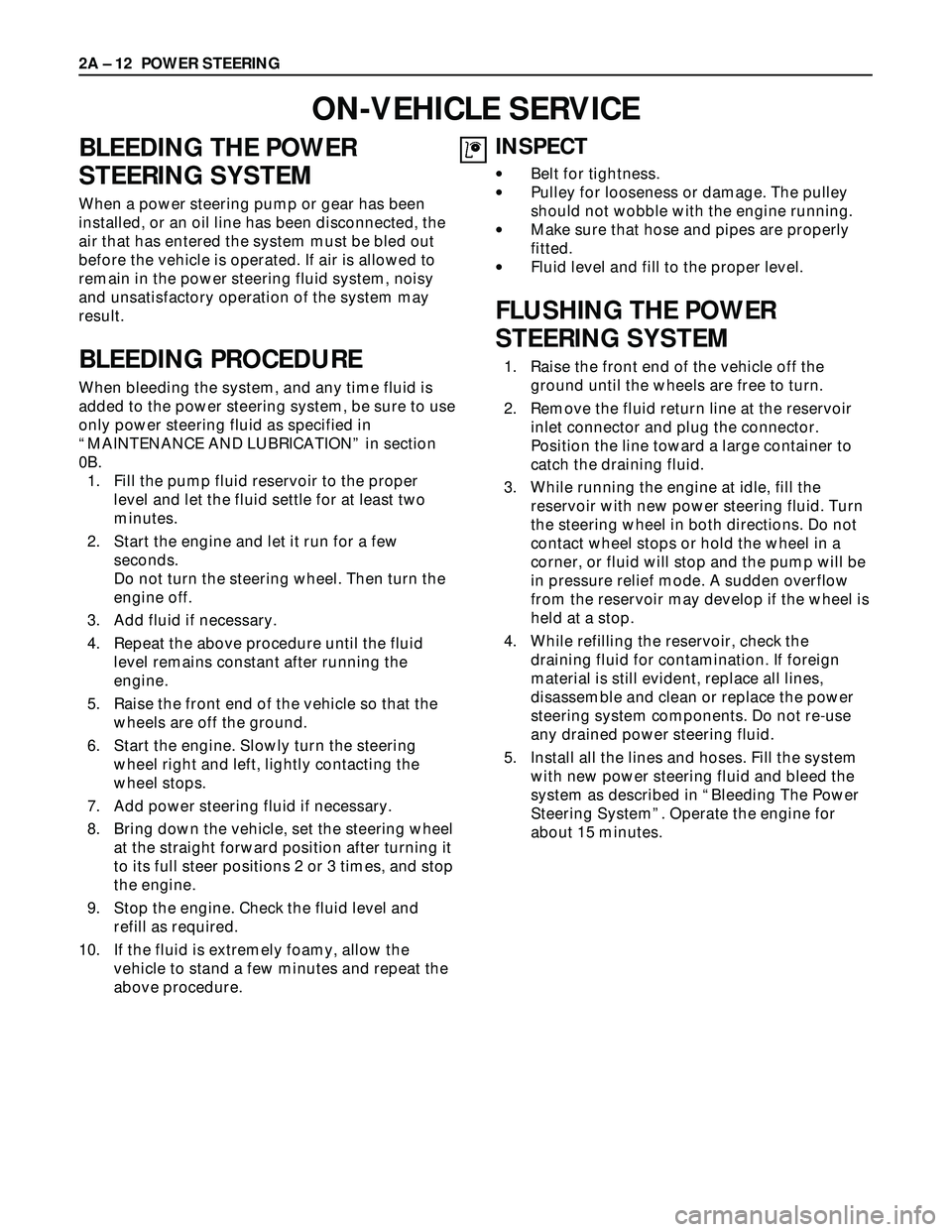
BLEEDING THE POWER
STEERING SYSTEM
When a power steering pump or gear has been
installed, or an oil line has been disconnected, the
air that has entered the system must be bled out
before the vehicle is operated. If air is allowed to
remain in the power steering fluid system, noisy
and unsatisfactory operation of the system may
result.
BLEEDING PROCEDURE
When bleeding the system, and any time fluid is
added to the power steering system, be sure to use
only power steering fluid as specified in
“MAINTENANCE AND LUBRICATION” in section
0B.
1. Fill the pump fluid reservoir to the proper
level and let the fluid settle for at least two
minutes.
2. Start the engine and let it run for a few
seconds.
Do not turn the steering wheel. Then turn the
engine off.
3. Add fluid if necessary.
4. Repeat the above procedure until the fluid
level remains constant after running the
engine.
5. Raise the front end of the vehicle so that the
wheels are off the ground.
6. Start the engine. Slowly turn the steering
wheel right and left, lightly contacting the
wheel stops.
7. Add power steering fluid if necessary.
8. Bring down the vehicle, set the steering wheel
at the straight forward position after turning it
to its full steer positions 2 or 3 times, and stop
the engine.
9. Stop the engine. Check the fluid level and
refill as required.
10. If the fluid is extremely foamy, allow the
vehicle to stand a few minutes and repeat the
above procedure.
INSPECT
•Belt for tightness.
•Pulley for looseness or damage. The pulley
should not wobble with the engine running.
•Make sure that hose and pipes are properly
fitted.
•Fluid level and fill to the proper level.
FLUSHING THE POWER
STEERING SYSTEM
1. Raise the front end of the vehicle off the
ground until the wheels are free to turn.
2. Remove the fluid return line at the reservoir
inlet connector and plug the connector.
Position the line toward a large container to
catch the draining fluid.
3. While running the engine at idle, fill the
reservoir with new power steering fluid. Turn
the steering wheel in both directions. Do not
contact wheel stops or hold the wheel in a
corner, or fluid will stop and the pump will be
in pressure relief mode. A sudden overflow
from the reservoir may develop if the wheel is
held at a stop.
4. While refilling the reservoir, check the
draining fluid for contamination. If foreign
material is still evident, replace all lines,
disassemble and clean or replace the power
steering system components. Do not re-use
any drained power steering fluid.
5. Install all the lines and hoses. Fill the system
with new power steering fluid and bleed the
system as described in “Bleeding The Power
Steering System”. Operate the engine for
about 15 minutes. 2A – 12 POWER STEERING
ON-VEHICLE SERVICE