Page 3078 of 3573
WIRING SYSTEM 8D – 485
Circuit Diagram (RHD)
D08RW649
2
B-37
B-37
1
4 3 B-37
B-37
6H-21
3.0
B/Y STARTER SW
(IG1)BATT.(+)
C-4 10A
ELEC.
IGN.C/B-2 30A
P/W, P/S, S/R0.85
L/W
3.0
B/L
2.0
L/B 2.0
L/B
2.0
L/B
0.5
B0.5
Y/R0.5
Y/B
0.5
Y/B0.5
L/Y1.25
L1.25
Y
0.5
L/Y
2.0
L/B 0.5
L/WB-19
BODY-RH 1.25
B 0.3
B
POWER
WINDOW
RELAY
SAFETY
STOP
SWLIMIT
SWSUN ROOF
SWSUN ROOF
MOTOR
A
3
H-45
4
H-21
2.0
B
BODY-LH 4
H-23
POWER WINDOW
SW6
H-454S-5
0.5
B
2.0
B
2.0
B
B
A
B
1 S-2
3
S-2
2 1 5S-5 2.0
L/B
B-2
L-1
OPEN
CLOSE0.5
B L-13
L-1 1
H-452
H-45 2
S-4
3
S-5
6
S-5OPEN
SUN ROOF CONTROL UNIT
CLOSE
1
S-5
4
S-4
1S-32
S-3
M
Page 3080 of 3573
WIRING SYSTEM 8D – 487
D08RW947
Circuit Diagram (LHD)
2
B-37
B-37
1
4 3 B-37
B-37
6H-21
3.0
B/Y STARTER SW
(IG1)BATT.(+)
C-4 10A
ELEC.
IGN.C/B-2 30A
P/W, P/S, S/R0.5
L/W
3.0
B/L
2.0
L/B 2.0
L/B
2.0
L/B
0.5
B0.5
Y/R0.5
Y/B
0.5
Y/B0.5
L/Y1.25
L1.25
Y
0.5
L/Y
2.0
L/B 0.5
L/WB-18
BODY-LH 1.25
B 0.3
B
POWER
WINDOW
RELAY
SAFETY
STOP
SWLIMIT
SWSUN ROOF
SWSUN ROOF
MOTOR
A
3
H-45
4
H-21
2.0
B
BODY-RH 4
H-23
POWER WINDOW
SW6
H-454S-5
0.5
B
2.0
B
2.0
B
B
A
B
1 S-2
3
S-2
2 1 5S-5 2.0
L/B
B-1
L-1
OPEN
CLOSE0.5
B L-13
L-1 1
H-452
H-45 2
S-4
3
S-5
6
S-5OPEN
SUN ROOF CONTROL UNIT
CLOSE
1
S-5
4
S-4
1S-32
S-3
M
Page 3132 of 3573
WIRING SYSTEM 8D – 539
Circuit Diagram (RHD 6VE1)-1
D08RW610
3.0
B/Y
0.5
L/W
0.5
L/W
0.5
L/W0.85
G/R
0.5
B/W0.3
R/G0.5
BR/R0.5
BR/G0.5
BR0.5
BR/Y0.5
BR/W0.5
R
0.5
BR/R0.5
BR/G0.5
BR0.5
BR/Y0.5
BR/W0.5
R 0.5
B/W 0.5
L/WC-4 10A
ELEC.IGN.
4WD
SWBRAKE
SW STOP
LIGHT
SW T.O.D. INDICATOR
(METER)
T.O.D. CONTROL UNIT
TAIL RELAY
(4)
ILLUMINATION
CONTROLLER
(3)
1
B-677
B-689H-25
3.0
B/Y
0.5
L/Y
0.5
L/YC-10 10A
METER,GAUGESTARTER SW
(IG1) STARTER SW
(IG1)
6
I-12
4
I-122I-12
3
I-1220H-25
17
B-68
5.0
W
0.85
G/W C-14 15A
STOP,
A/T CONT. BATT.(+)
STOP LIGHT
2
B-68 5
H-2726I-9
15I-9
15
B-689H-2721I-9
14
B-682H-2722I-9
13
B-6815H-2723I-9
16
B-683H-2716I-9
18
B-6816H-257
H-32 17
I-9 6
H-26
0.85
G/W 0.85
G/W(W/ CRUISE CONTROL)
0.85
G/Y
0.85
G/Y 0.85
G/Y
B-131B-13
4
B-141B-14
2
RR 1 2 3 AUTO CHECK
A
Page 3417 of 3573

8J±38EXTERIOR/INTERIOR TRIM
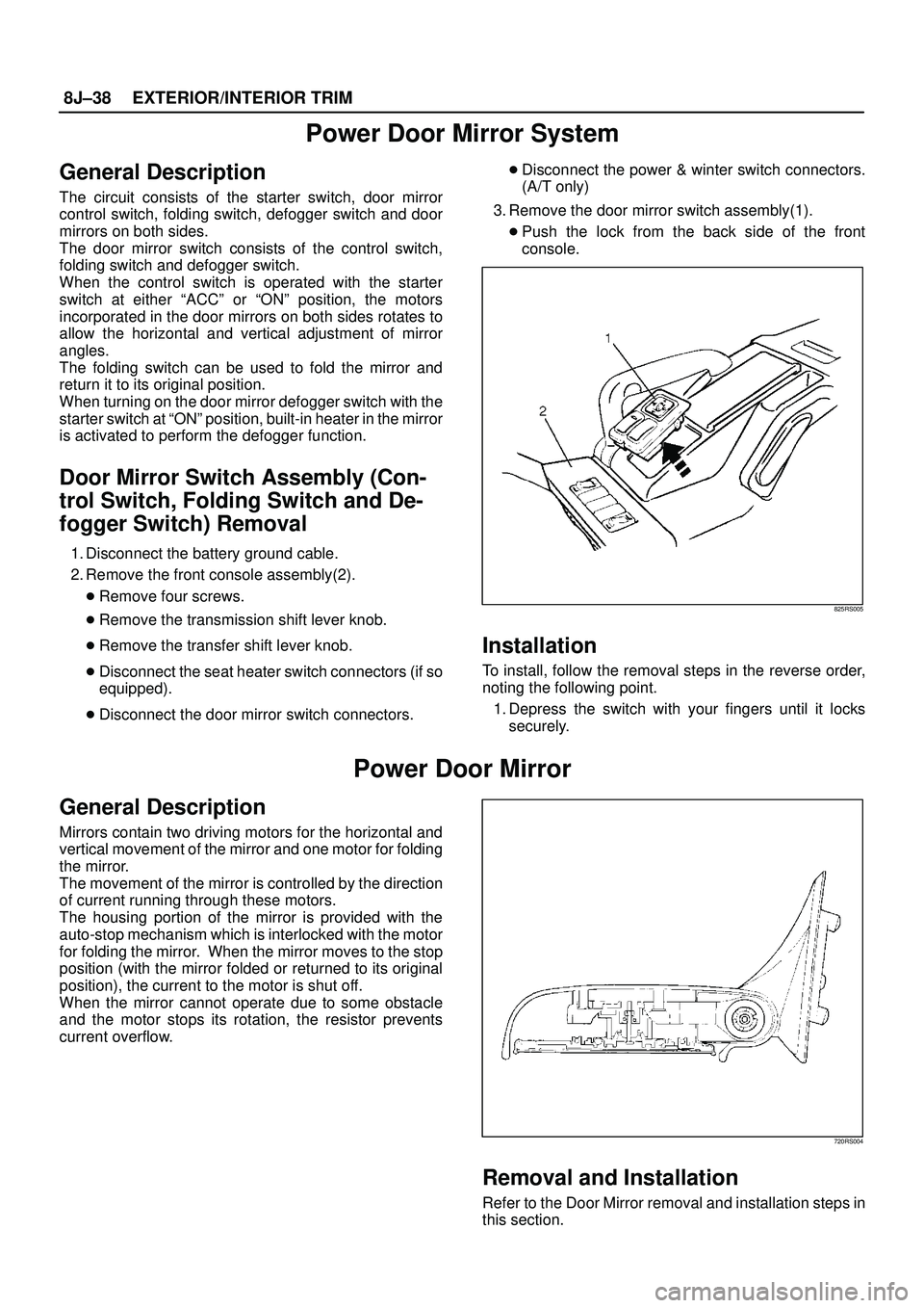
Power Door Mirror System
General Description
The circuit consists of the starter switch, door mirror
control switch, folding switch, defogger switch and door
mirrors on both sides.
The door mirror switch consists of the control switch,
folding switch and defogger switch.
When the control switch is operated with the starter
switch at either ªACCº or ªONº position, the motors
incorporated in the door mirrors on both sides rotates to
allow the horizontal and vertical adjustment of mirror
angles.
The folding switch can be used to fold the mirror and
return it to its original position.
When turning on the door mirror defogger switch with the
starter switch at ªONº position, built-in heater in the mirror
is activated to perform the defogger function.
Door Mirror Switch Assembly (Con-
trol Switch, Folding Switch and De-
fogger Switch) Removal
1. Disconnect the battery ground cable.
2. Remove the front console assembly(2).
�Remove four screws.
�Remove the transmission shift lever knob.
�Remove the transfer shift lever knob.
�Disconnect the seat heater switch connectors (if so
equipped).
�Disconnect the door mirror switch connectors.�Disconnect the power & winter switch connectors.
(A/T only)
3. Remove the door mirror switch assembly(1).
�Push the lock from the back side of the front
console.
825RS005
Installation
To install, follow the removal steps in the reverse order,
noting the following point.
1. Depress the switch with your fingers until it locks
securely.
Power Door Mirror
General Description
Mirrors contain two driving motors for the horizontal and
vertical movement of the mirror and one motor for folding
the mirror.
The movement of the mirror is controlled by the direction
of current running through these motors.
The housing portion of the mirror is provided with the
auto-stop mechanism which is interlocked with the motor
for folding the mirror. When the mirror moves to the stop
position (with the mirror folded or returned to its original
position), the current to the motor is shut off.
When the mirror cannot operate due to some obstacle
and the motor stops its rotation, the resistor prevents
current overflow.
720RS004
Removal and Installation
Refer to the Door Mirror removal and installation steps in
this section.
Page 3478 of 3573

SUPPLEMENTAL RESTRAINT SYSTEM9J±41
Installation
1. Install the combination switch assembly with SRS
coil.
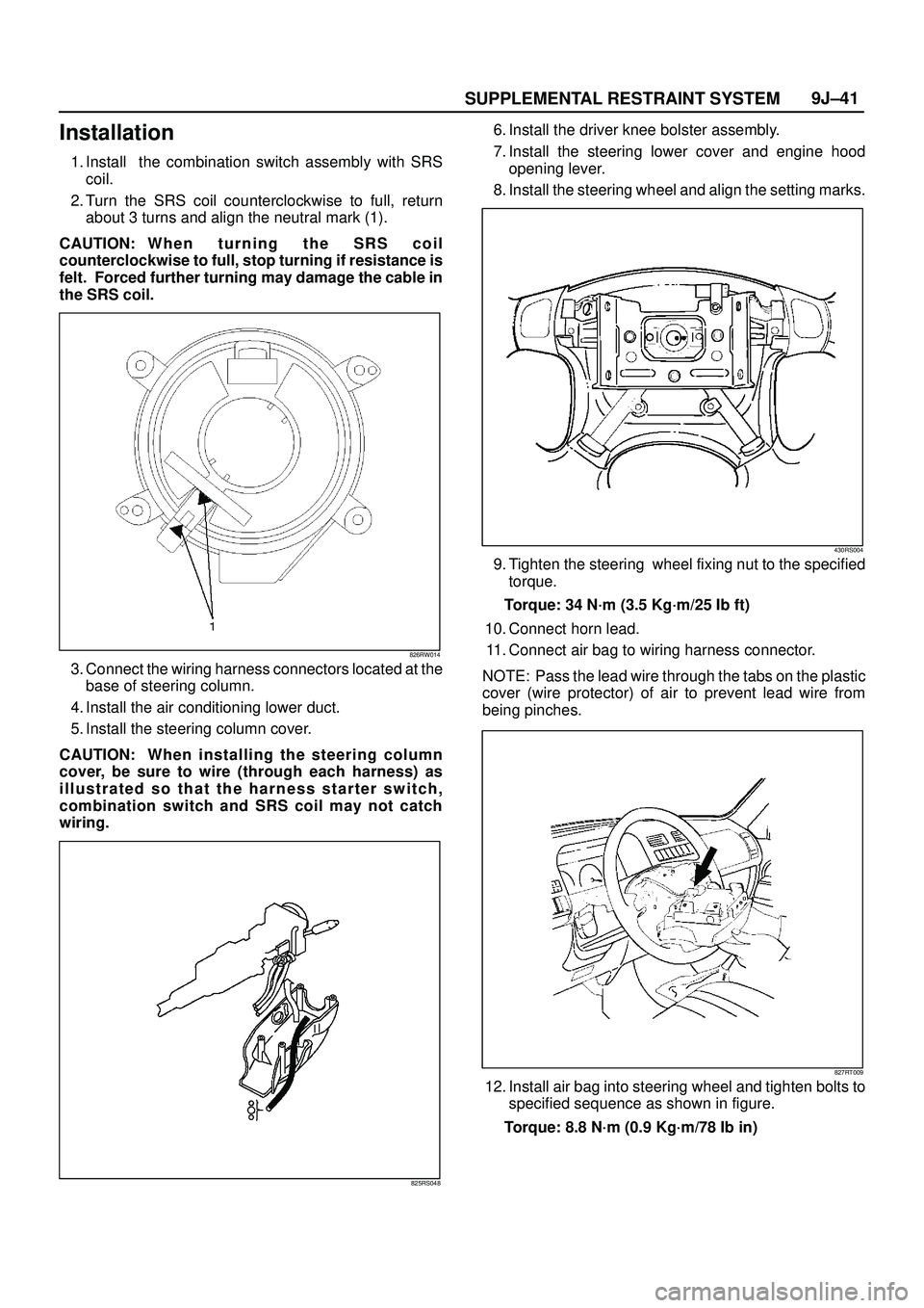
2. Turn the SRS coil counterclockwise to full, return
about 3 turns and align the neutral mark (1).
CAUTION: W h e n t u r n i n g t h e S R S c o i l
counterclockwise to full, stop turning if resistance is
felt. Forced further turning may damage the cable in
the SRS coil.
826RW014
3. Connect the wiring harness connectors located at the
base of steering column.
4. Install the air conditioning lower duct.
5. Install the steering column cover.
CAUTION: When installing the steering column
cover, be sure to wire (through each harness) as
illustrated so that the harness starter switch,
combination switch and SRS coil may not catch
wiring.
825RS048
6. Install the driver knee bolster assembly.
7. Install the steering lower cover and engine hood
opening lever.
8. Install the steering wheel and align the setting marks.
430RS004
9. Tighten the steering wheel fixing nut to the specified
torque.
Torque: 34 N´m (3.5 Kg´m/25 Ib ft)
10. Connect horn lead.
11. Connect air bag to wiring harness connector.
NOTE: Pass the lead wire through the tabs on the plastic
cover (wire protector) of air to prevent lead wire from
being pinches.
827RT009
12. Install air bag into steering wheel and tighten bolts to
specified sequence as shown in figure.
Torque: 8.8 N´m (0.9 Kg´m/78 Ib in)
Page 3483 of 3573

SUPPLEMENTAL RESTRAINT SYSTEM 9J±46
NOTE: S R S c o i l i s a p a r t o f combination switch
assembly, which cannot be replaced separately.
Therefore, be sure not to remove the SRS coil from the
combination switch assembly.
15. Remove the snap ring.
16. Remove the cushion rubber.
17. Disconnect shift lock cable (A/T only).
18. Disconnect the starter switch harness connector
located base of steering column.
19. Remove steering lock cylinder assembly.
20. Apply a setting mark across the universal joint and
steering shaft to reassemble the parts in their original
position.
431RS013
21. Remove steering column assembly.
Installation
1. Install the steering column assembly and align the
setting marks on the universal joint and steering shaft
made during removal.
431RS013
2. Tighten the steering column fixing bolts (dash panel
side) to the specified torque.
Torque: 19 N´m (1.9 Kg´m/14 Ib ft)
3. Tighten the steering column fixing bolts (Pedal
bracket) to the specified torque.
Torque: 17 N´m (1.7 Kg´m/13 Ib ft)
4. Tighten the universal joint to the specified torque.
Torque: 25 N´m (2.6 Kg´m/18 Ib ft)
5. Install steering lock cylinder assembly.
6. Connect shift lock cable (For A/T)
7. Install cushion rubber.
8. Install snap ring.
9. Install the combination switch assembly with SRS
coil.
10. Connect the wiring harness connector located on the
base of steering column.
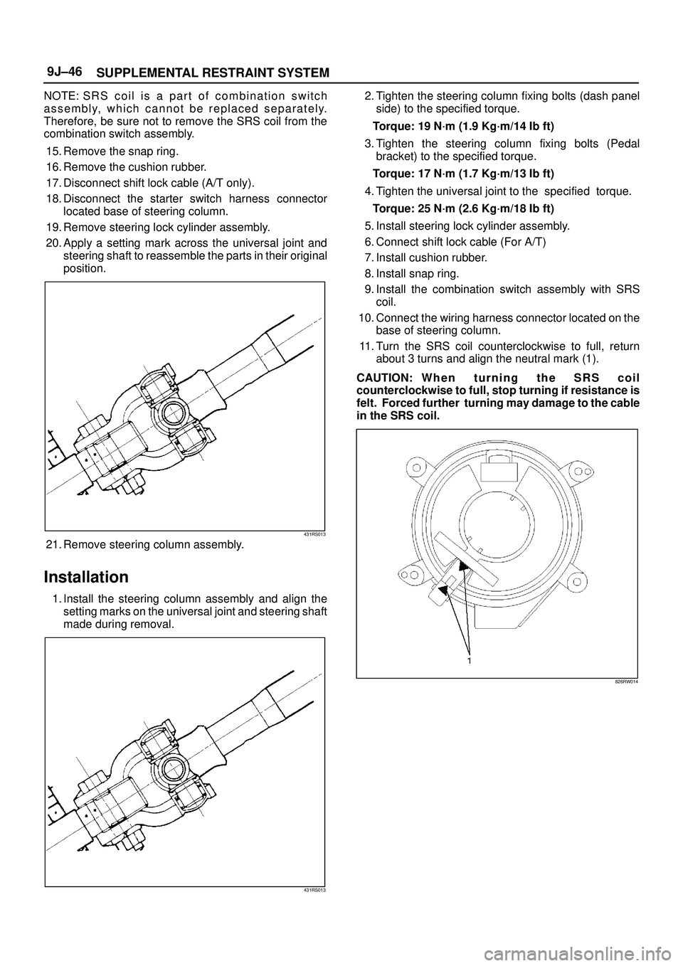
11. Turn the SRS coil counterclockwise to full, return
about 3 turns and align the neutral mark (1).
CAUTION: W h e n t u r n i n g t h e S R S c o i l
counterclockwise to full, stop turning if resistance is
felt. Forced further turning may damage to the cable
in the SRS coil.
826RW014