Page 2910 of 3573
WIRING SYSTEM 8DÐ317
Circuit Diagram (RHD)-1
ALARM & RELAY
CONTROL UNITRR WIPER/
WASHER SW
B-2
BODY-LH
A
B
4
B-77
I-16
8
B-7
B-7
2.0
B 0.85
B 0.5
L/B0.5
L/B0.5
L/B 0.5
L/B3.0
B/R
C-6 10A
RR WIPER&WASHER
9
B-18
BODY-RH2.0
B
B-7 AUTO STOP
0.5
LG/L2
CB-7 MOTORH-25
3 314
I-16H-16
I-16
0.5
LG/R0.5
LB
0.5
LG/W 0.5
LB
D 0.5
LG/W0.5
LG/W0.3
R/G 0.85
G/R
3 STARTER SW
(IG2)
ILLUMINATION
CONTROLLER(3)TAIL RELAY
(4)
I-16
I-16
18
B-7
WASHER WIPER22H-2511 862
H-26
RR
WASHER RR
WIPER
D08RW643
Page 2913 of 3573
8DÐ320 WIRING SYSTEM
Circuit Diagram (LHD)-1
ALARM & RELAY
CONTROL UNITRR WIPER/
WASHER SW
B-2
BODY-RH
A
B
4
B-77
I-16
8
B-7
B-7
0.85
B 0.5
L/B0.5
L/B0.5
L/B 0.5
L/B3.0
B/R
C-6 10A
RR WIPER&WASHER
9
B-7 AUTO STOP
0.5
LG/L2
CB-7 MOTORH-25
3 21 13
I-16H-16
I-16
0.5
LG/R0.5
LB
0.5
LG/W 0.5
LB
D 0.5
LG/W0.5
LG/W0.3
R/G 0.85
G/R
3 STARTER SW
(IG2)
ILLUMINATION
CONTROLLER(3)TAIL RELAY
(4)
I-16
I-16
18
B-7
WASHER WIPER4H-2513 862
H-25
RR
WASHER RR
WIPER
D08RW072
Page 2918 of 3573

WIRING SYSTEM 8DÐ325
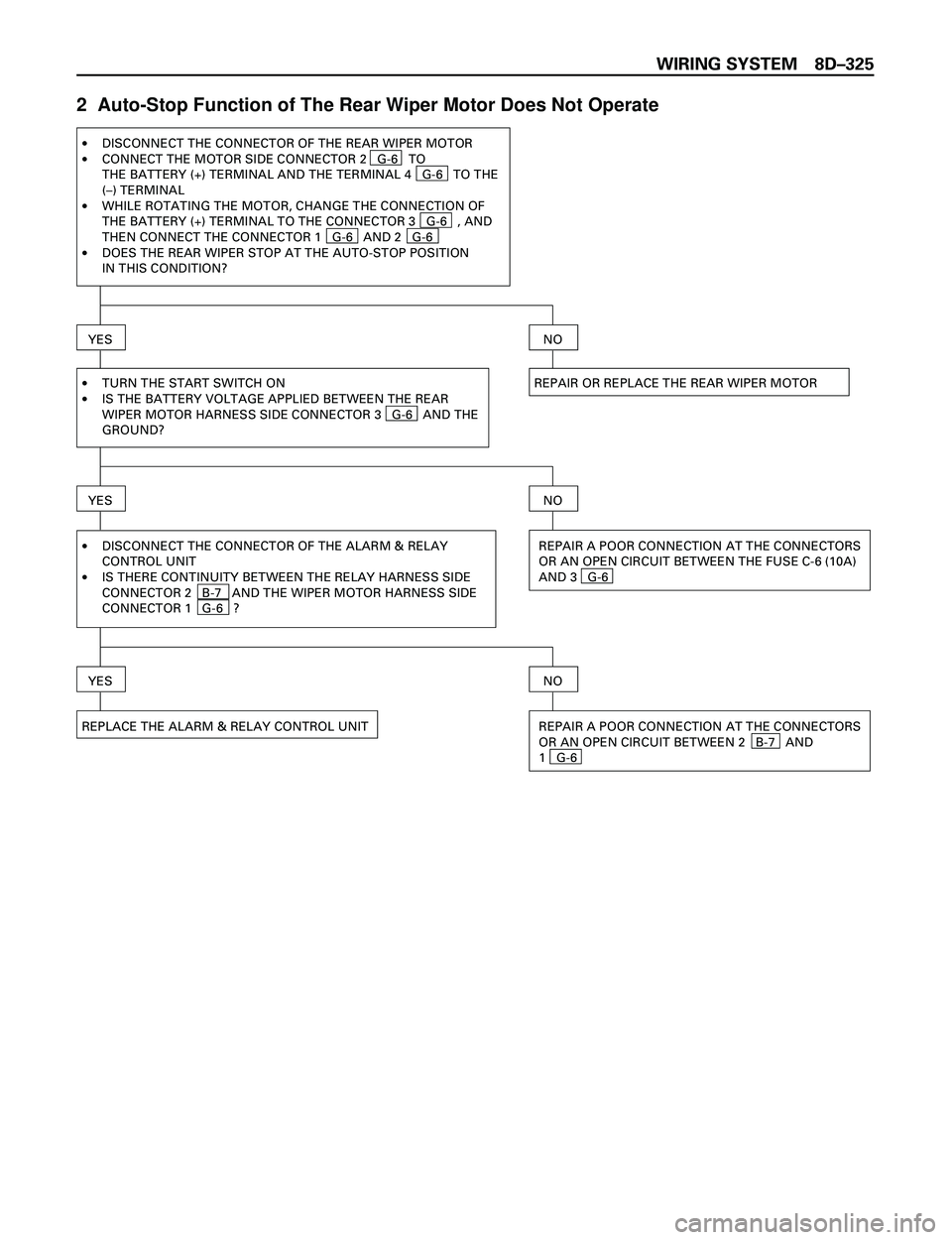
2 Auto-Stop Function of The Rear Wiper Motor Does Not Operate
REPAIR OR REPLACE THE REAR WIPER MOTOR ·
·
·
·DISCONNECT THE CONNECTOR OF THE REAR WIPER MOTOR
CONNECT THE MOTOR SIDE CONNECTOR 2 G-6 TO
THE BATTERY (+) TERMINAL AND THE TERMINAL 4 G-6 TO THE
(–) TERMINAL
WHILE ROTATING THE MOTOR, CHANGE THE CONNECTION OF
THE BATTERY (+) TERMINAL TO THE CONNECTOR 3 G-6 , AND
THEN CONNECT THE CONNECTOR 1 G-6 AND 2 G-6
DOES THE REAR WIPER STOP AT THE AUTO-STOP POSITION
IN THIS CONDITION?
YESNO
·
·TURN THE START SWITCH ON
IS THE BATTERY VOLTAGE APPLIED BETWEEN THE REAR
WIPER MOTOR HARNESS SIDE CONNECTOR 3 G-6 AND THE
GROUND?
YESNO
·
·DISCONNECT THE CONNECTOR OF THE ALARM & RELAY
CONTROL UNIT
IS THERE CONTINUITY BETWEEN THE RELAY HARNESS SIDE
CONNECTOR 2 B-7 AND THE WIPER MOTOR HARNESS SIDE
CONNECTOR 1 G-6 ?REPAIR A POOR CONNECTION AT THE CONNECTORS
OR AN OPEN CIRCUIT BETWEEN THE FUSE C-6 (10A)
AND 3 G-6
REPLACE THE ALARM & RELAY CONTROL UNIT
YESNO
REPAIR A POOR CONNECTION AT THE CONNECTORS
OR AN OPEN CIRCUIT BETWEEN 2 B-7 AND
1 G-6
Page 2920 of 3573
WIRING SYSTEM 8DÐ327
5 Rotation of The Rear Wiper Motor Does Not Stop
·IS THE CONTINUITY IN THE REAR WIPER & WASHER
SWITCH NORMAL?
·DISCONNECT THE ALARM & RELAY CONTROL
UNIT CONNECTORS
TURN THE STARTER SW ON
IS THE BATTERY VOLTAGE APPLIED BETWEEN
HARNESS SIDE CONNECTOR 2 B-7 AND
THE GROUND?
YES
REPAIR OR REPLACE THE REAR WIPER & WASHER
SWITCH
NO
YES
REPAIR OR REPLACE THE RR WIPER MOTOR REPLACE THE ALARM & RELAY CONTROL UNIT
NO
Page 2933 of 3573
8D – 340 WIRING SYSTEM
4. Wiper On The Left (Or Right) Side Does Not Stop
•STOP THE WIPER MOTOR AT THE AUTO-STOP
POSITION
YES
REPAIR A SHORT CIRCUIT BETWEEN
3 C-23 AND 7 I-4 (3 C-30 AND
5 I-4 )
NO
•IS THE CONTINUITY IN THE HEADLIGHT
WIPER SWITCH NORMAL?
YES
REPAIR OR REPLACE THE SWITCH
NO
•DISCONNECT THE WIPER MOTOR CONNECTOR•IS THERE CONTINUITY BETWEEN THE MOTOR
SIDE CONNECTOR TERMINALS 4 C-23 AND
2 C-23 (4 C-30 AND 2 C-30 )?
YES
REPAIR A SHORT CIRCUIT BETWEEN
4 C-23 AND 8 I-4 (4 C-30 AND
4 I-4 )
NO
REPAIR THE WIPER MOTOR AUTO-STOP MECHANISM,
OR REPLACE THE MOTOR
•DISCONNECT THE HEADLIGHT WIPER SWITCH
CONNECTOR
•TURN THE STARTER SWITCH ON•DOES THE WIPER MOTOR REMAIN STOPPED?
Page 2993 of 3573

8DÐ400 WIRING SYSTEM
ITEM MALFUNCTION POSSIBLE CAUSE DETECTING METHOD REMARKS
Even when door
unlocked with
key, alarm
operates.
Alarm does not
operate even with
tailgate open.
Even when
tailgate is opened
with key, alarm
does not stop.
Even when
engine hood is
opened with
remote release,
alarm does not
operate
Even when
starter switch is
turned, alarm
does not stop
Indicator light
continues
flashingRefer to ÒConnector
check tableÓ in this
system.
Refer to ÒConnector
check tableÓ in this
system.
Refer to ÒConnector
check tableÓ in this
system. Defective contact of detect
switch, or damaged switch wiring.
Door detect switch is assembled
to wrong door.
Defective contact of tailgate
switch, or defective wiring.
Defective contact of tailgate
detect switch, or damage wiring.
Damaged engine hood switch or
wiring.
Defective contact of starter
switch.
Damaged door switch, or a short
circuit in wiring.
Damaged tamper switch, or a
short circuit in wiring.Check the control unit connector.
When key is turned to lock
position, alarm stops.
When luggage room light switch
is turned on with tailgate open,
luggage room light does not
come on.
Check the control unit connector.
With starter switch turned to
ÒACCÓ position, audio, cigarette
lighter and door mirrors (on
ÒACCÓ circuit) do not operate.
After closing door, dome light and
courtesy light remain on.
Check the control unit connector. F
G
H
I
J
K
Page 2994 of 3573

WIRING SYSTEM 8DÐ401
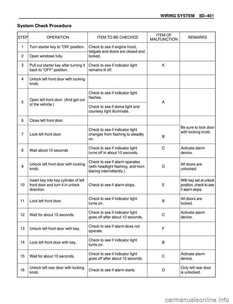
System Check Procedure
STEP OPERATION ITEM TO BE CHECKEDITEM OF
REMARKS
MALFUNCTION
Be sure to lock door
with locking knob.
Activate alarm
device.
All doors are
unlocked.
With key set at unlock
position, check to see
if alarm stops.
All doors are
locked.
Activate alarm
device.
Activate alarm
device.
Only left rear door
is unlocked. Check to see if engine hood,
tailgate and doors are closed and
locked.
Check to see if indicator light
remains lit off.
Check to see if indicator light
flashes.
Check to see if dome light and
courtesy light illuminate.
Check to see if indicator light
changes from flashing to steadily
on.
Check to see if indicator light
turns off in about 10 seconds.
Check to see if alarm operates
(with headlight flashing, and horn
blaring intermittently.)
Check to see if alarm stops.
Check to see if indicator light
turns on.
Check to see if indicator light
goes off after about 10 seconds.
Check to see if alarm does not
operate.
Check to see if indicator light
turns on.
Check to see if indicator light
goes off after about 10 seconds.
Check to see if alarm starts. Turn starter key to ÒONÓ position.
Open windows fully.
Pull out starter key after turning it
back to ÒOFFÓ position.
Unlock left front door with locking
knob.
Open left front door. (And get out
of the vehicle.)
Close left front door.
Lock left front door.
Wait about 10 seconds
Unlock left front door with locking
knob.
Insert key into key cylinder of left
front door and turn it in unlock
direction.
Lock left front door.
Wait for about 10 seconds.
Unlock left front door with key.
Lock left front door with key.
Wait for about 10 seconds.
Unlock left rear door with locking
knob.K
A
B
C
D
E
B
C
F
B
C
D 1
2
3
4
5
6
7
8
9
10
11
12
13
14
15
16
Page 2997 of 3573
8DÐ404 WIRING SYSTEM
STEP OPERATION ITEM TO BE CHECKEDITEM OF
REMARKS
MALFUNCTION
Activate alarm
device. Check to see if indicator light
goes off after about 10 seconds.
Check to see if alarm operates.
Check to see if alarm stops. Wait about 10 seconds.
Open engine hood with engine
hood release handle.
Insert key into starter switch and
turn it to ÒACCÓ position.C
I
J 45
46
47
NOTE:When the connector of the antiÐtheft & keyless entry control unit is disconnected, the starter is inoperative.
In the checking of short wheel base model, Step Nos. 16 through 21 and Step Nos. 31 through 36 are omitted.