1998 ISUZU TROOPER weight
[x] Cancel search: weightPage 85 of 3573
00 Ð 46 SERVICE INFORMATION
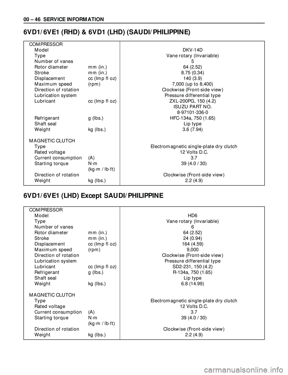
COMPRESSOR
Model DKV-14D
Type Vane rotary (Invariable)
Number of vanes 5
Rotor diameter mm (in.) 64 (2.52)
Stroke mm (in.) 8.75 (0.34)
Displacement cc (Imp fl oz) 140 (3.9)
Maximum speed (rpm) 7,000 (up to 8,400)
Direction of rotation Clockwise (Front-side view)
Lubrication system Pressure differential type
Lubricant cc (Imp fl oz) ZXL-200PG, 150 (4.2)
ISUZU PART NO.
8-97101-336-0
Refrigerant g (lbs.) HFC-134a, 750 (1.65)
Shaft seal Lip type
Weight kg (lbs.) 3.6 (7.94)
MAGNETIC CLUTCH
Type Electromagnetic single-plate dry clutch
Rated voltage 12 Volts D.C.
Current consumption (A) 3.7
Starting torque Nám 39 (4.0 / 30)
(kgám / lbáft)
Direction of rotation Clockwise (Front-side view)
Weight kg (lbs.) 2.2 (4.9)
6VD1/6VE1 (RHD) & 6VD1 (LHD) (SAUDI/PHILIPPINE)
6VD1/6VE1 (LHD) Except SAUDI/PHILIPPINE
COMPRESSOR
Model HD6
Type Vane rotary (Invariable)
Number of vanes 6
Rotor diameter mm (in.) 64 (2.52)
Stroke mm (in.) 24 (0.94)
Displacement cc (Imp fl oz) 164 (4.59)
Maximum speed (rpm) 9,000
Direction of rotation Clockwise (Front-side view)
Lubrication system Pressure differential type
Lubricant cc (Imp fl oz) SD2-231, 150 (4.2)
Refrigerant g (lbs.) R-134a, 750 (1.65)
Shaft seal Lip type
Weight kg (lbs.) 6.8 (14.99)
MAGNETIC CLUTCH
Type Electromagnetic single-plate dry clutch
Rated voltage 12 Volts D.C.
Current consumption (A) 3.7
Starting torque Nám 39 (4.0 / 30)
(kgám / lbáft)
Direction of rotation Clockwise (Front-side view)
Weight kg (lbs.) 2.2 (4.9)
Page 86 of 3573
SERVICE INFORMATION 00 Ð 47
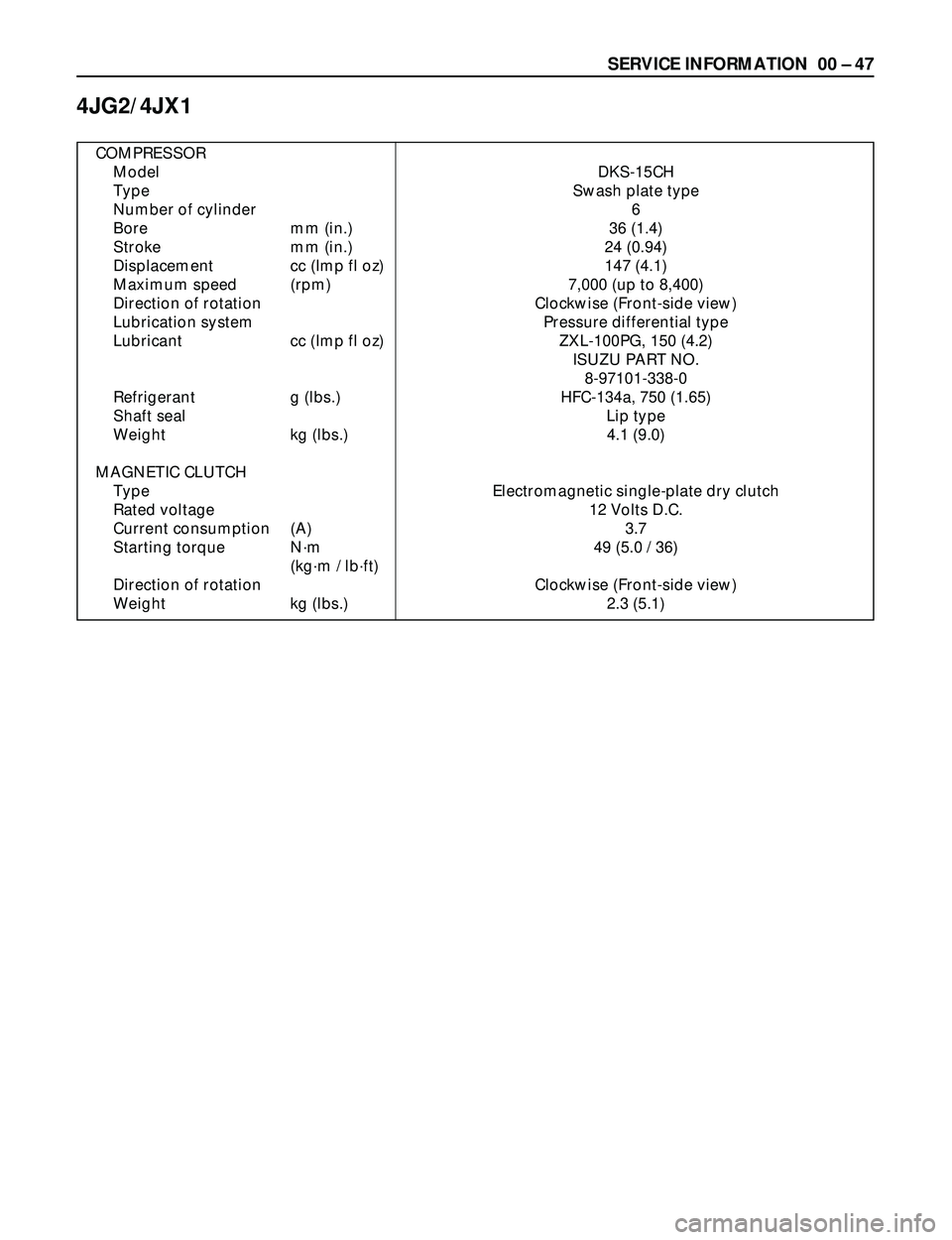
4JG2/4JX1
COMPRESSOR
Model DKS-15CH
Type Swash plate type
Number of cylinder 6
Bore mm (in.) 36 (1.4)
Stroke mm (in.) 24 (0.94)
Displacement cc (Imp fl oz) 147 (4.1)
Maximum speed (rpm) 7,000 (up to 8,400)
Direction of rotation Clockwise (Front-side view)
Lubrication system Pressure differential type
Lubricant cc (Imp fl oz) ZXL-100PG, 150 (4.2)
ISUZU PART NO.
8-97101-338-0
Refrigerant g (lbs.) HFC-134a, 750 (1.65)
Shaft seal Lip type
Weight kg (lbs.) 4.1 (9.0)
MAGNETIC CLUTCH
Type Electromagnetic single-plate dry clutch
Rated voltage 12 Volts D.C.
Current consumption (A) 3.7
Starting torque Nám 49 (5.0 / 36)
(kgám / lbáft)
Direction of rotation Clockwise (Front-side view)
Weight kg (lbs.) 2.3 (5.1)
Page 358 of 3573
2A – 56 SUPPLEMENTAL RESTRAINT SYSTEM STEERING WHEEL & COLUMN
3
41
2
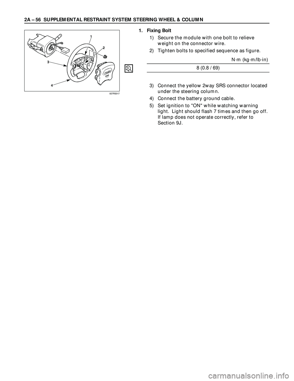
1. Fixing Bolt
1) Secure the module with one bolt to relieve
weight on the connector wire.
2) Tighten bolts to specified sequence as figure.
N·m (kg·m/lb·in)
8 (0.8 / 69)
3) Connect the yellow 2way SRS connector located
under the steering column.
4) Connect the battery ground cable.
5) Set ignition to "ON" while watching warning
light. Light should flash 7 times and then go off.
If lamp does not operate correctly, refer to
Section 9J.
827RS017
Page 361 of 3573

SUPPLEMENTAL RESTRAINT SYSTEM STEERING WHEEL & COLUMN 2A Ð 59
INSTALLATION
4. Steering Wheel
Align the setting marks made when removing.
CAUTION:
Never apply force to the setting wheel in direction of the
shaft by using a hammer or other impact tools in an
attempt to install the steering wheel. The setting shaft is
designed as an energy absorbing unit.
3. Steering Wheel Fixing Nut
Steering Wheel Nut Torque Nám (kgám/lbáft)
34 (3.5 / 25)
2. Horn Lead
1. Inflator Module
1) Support the module and carefully connect the
module connector.
CAUTION:
·Never use the air bag assembly from another vehicle.
Use only the air bag assembly for "UBS".
·When replace the inflator module, use only same parts
number assembly. If different parts number assembly is
installed, the air bag system can not function correctly
because it has different characteristic.
NOTE:
Pass the lead wire through the tabs on the plastic
cover (wire protector) of inflator to prevent lead wire
from being pinches.
2) Secure the module with one bolt to relieve
weight on the connector wire.
3) Tighten bolts to specified sequence as figure.
Inflator module Bolt Torque Nám (kgám/lbáin)
8 (0.8 / 69)
4) Connect the yellow 2way SRS connector located
under the steering column.
5) Connect the battery ground cable.
6) Set ignition to "ON" while watching warning
light. Light should flash 7 times and then go off.
If lamp does not operate correctly, refer to
Section 9J.
3
41
2
827RS017
Page 365 of 3573

SUPPLEMENTAL RESTRAINT SYSTEM STEERING WHEEL & COLUMN 2A Ð 63
5. Steering Wheel
Align the setting marks made when removing.
CAUTION:
Never apply force to the steering wheel in direction of the
shaft by using a hammer or other impact tools in an
attempt to remove the steering wheel. The steering shaft
is designed as an energy absorbing unit.
Tighten the steering wheel fixing nut to the specified
torque.
Steering Wheel Nut Torque Nám (kgám/lbáft)
34 (3.5 / 25)
4. Inflator Module
1) Support the module and carefully connect the
module connector.
CAUTION:
·Never use the air bag assembly from another vehicle.
Use only the air bag assembly for "UBS".
·When replace the inflator module, use only same parts
number assembly. If different parts number assembly is
installed, the air bag system can not function correctly
because it has different characteristic.
NOTE:
Pass the lead wire through the tabs on the plastic
cover (wire protector) of inflator to prevent lead wire
from being pinched.
2) Secure the module with one bolt to relieve
weight on the connector wire.
3) Tighten bolts to specified sequence as figure.
Inflator Module Bolt Torque Nám (kgám/lbáin)
8 (0.8 / 69)
3. Steering Lower Cover
Install the engine hood opening lever.
2. Lower Cluster Assembly
1. Front Console Assembly
1) Install the transmission (for M/T) and transfer
control lever knob.
2) Install the wiring harness connectors.
Connect the battery ground cable.
Turn the ignition to "ON" while watching warning light.
Light should flash 7 times and then go off. If lamp
does not operate correctly, refer to Section 9J.
3
41
2
827RS017
Page 370 of 3573
2A Ð 68 SUPPLEMENTAL RESTRAINT SYSTEM STEERING WHEEL & COLUMN
3
41
2
4. Inflator Module
1) Support the module and carefully connect the
module connector.
CAUTION:
·Never use the air bag assembly from another vehicle.
Use only the air bag assembly for "UBS".
·When replace the inflator module, use only same parts
number assembly. If different parts number assembly is
installed, the air bag system can not function correctly
because it has different characteristic.
NOTE:
Pass the lead wire through the tabs on the plastic
cover (wire protector) of inflator to prevent lead wire
from being pinched.
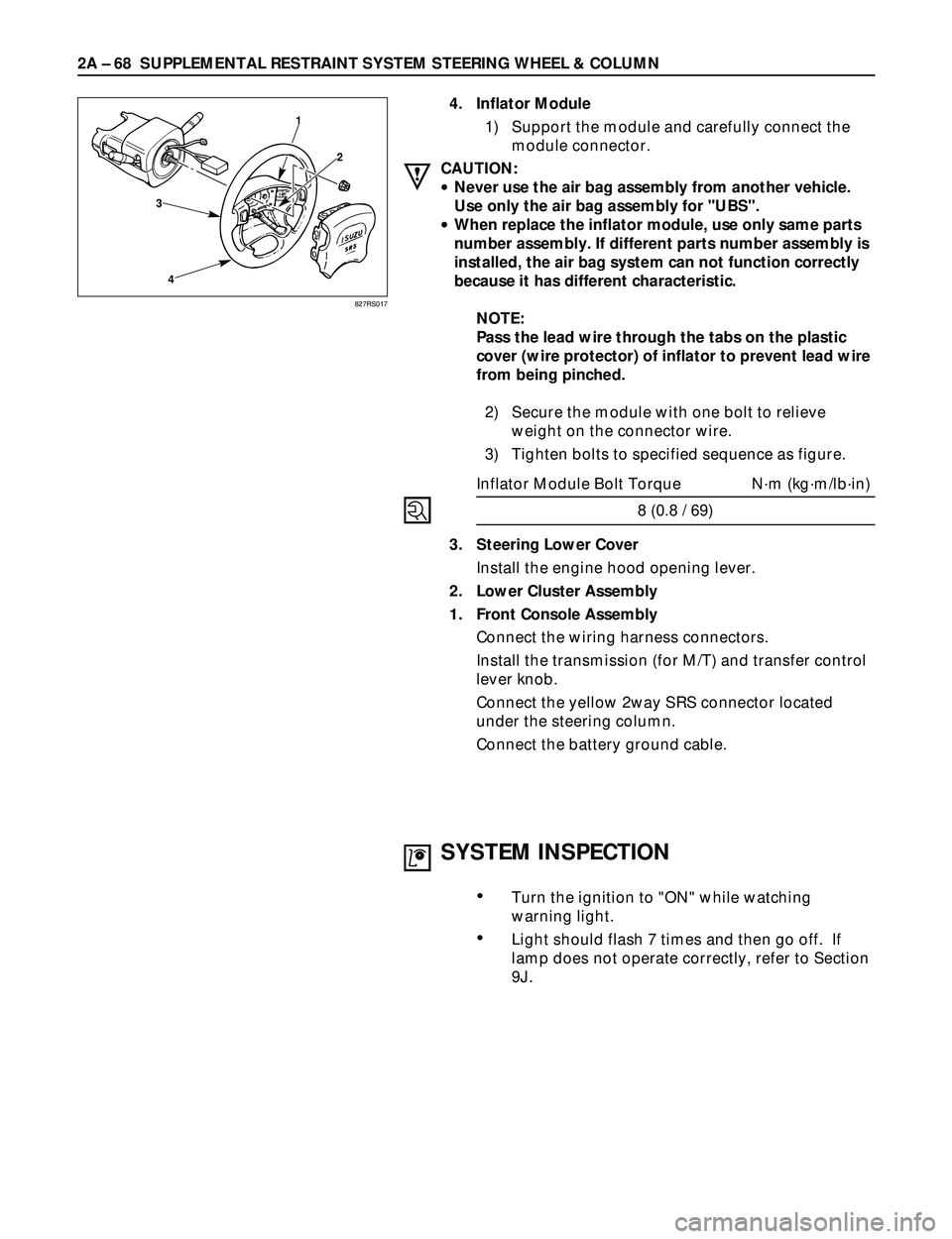
2) Secure the module with one bolt to relieve
weight on the connector wire.
3) Tighten bolts to specified sequence as figure.
Inflator Module Bolt Torque Nám (kgám/lbáin)
8 (0.8 / 69)
3. Steering Lower Cover
Install the engine hood opening lever.
2. Lower Cluster Assembly
1. Front Console Assembly
Connect the wiring harness connectors.
Install the transmission (for M/T) and transfer control
lever knob.
Connect the yellow 2way SRS connector located
under the steering column.
Connect the battery ground cable.
827RS017
SYSTEM INSPECTION
¥Turn the ignition to "ON" while watching
warning light.
¥Light should flash 7 times and then go off. If
lamp does not operate correctly, refer to Section
9J.
Page 375 of 3573
SUPPLEMENTAL RESTRAINT SYSTEM STEERING WHEEL & COLUMN 2A Ð 73
Starter switch
harness
Combination
switch harness
Inflator module
harness
Setting cowl
(Lower)
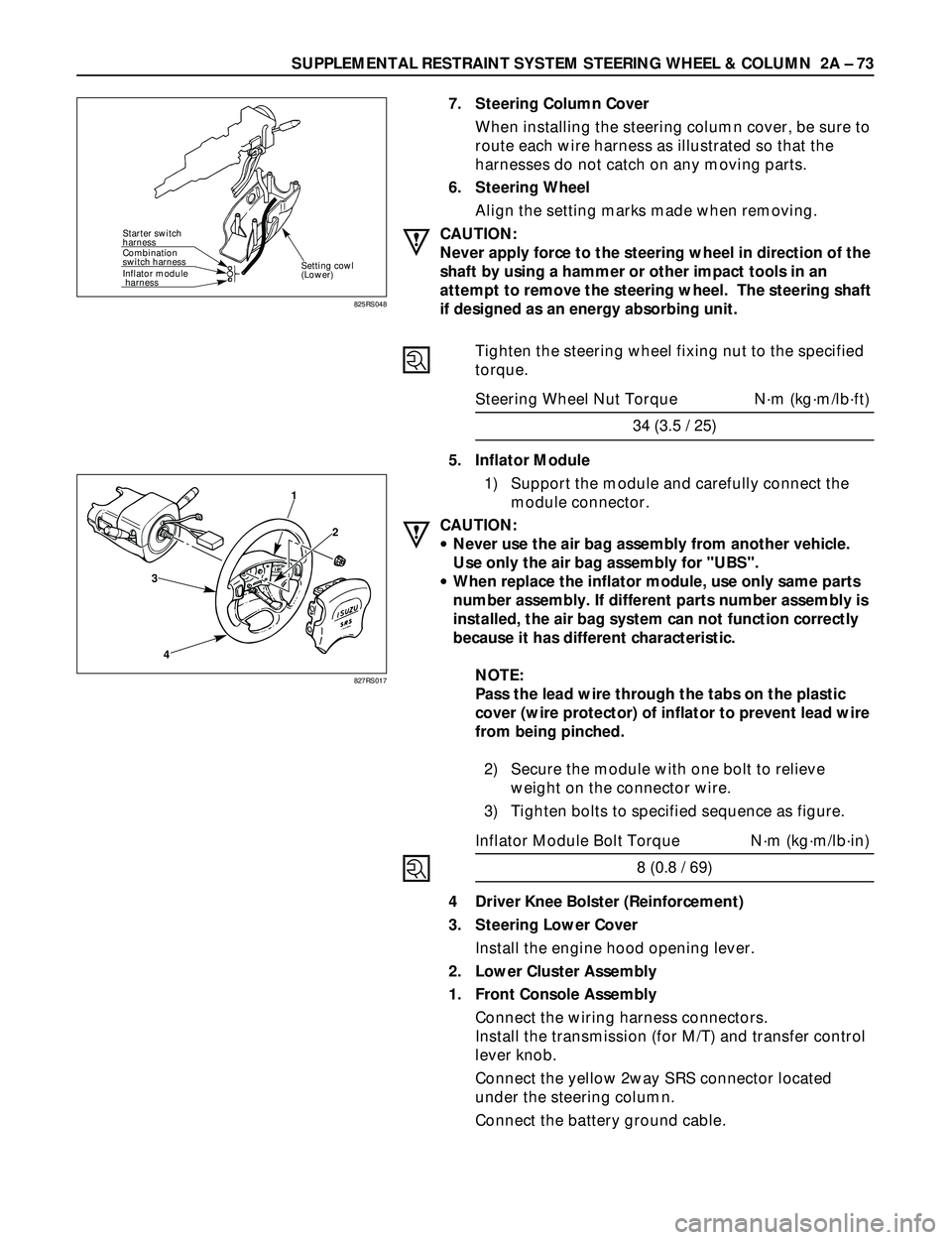
7. Steering Column Cover
When installing the steering column cover, be sure to
route each wire harness as illustrated so that the
harnesses do not catch on any moving parts.
6. Steering Wheel
Align the setting marks made when removing.
CAUTION:
Never apply force to the steering wheel in direction of the
shaft by using a hammer or other impact tools in an
attempt to remove the steering wheel. The steering shaft
if designed as an energy absorbing unit.
Tighten the steering wheel fixing nut to the specified
torque.
Steering Wheel Nut Torque Nám (kgám/lbáft)
34 (3.5 / 25)
5. Inflator Module
1) Support the module and carefully connect the
module connector.
CAUTION:
·Never use the air bag assembly from another vehicle.
Use only the air bag assembly for "UBS".
·When replace the inflator module, use only same parts
number assembly. If different parts number assembly is
installed, the air bag system can not function correctly
because it has different characteristic.
NOTE:
Pass the lead wire through the tabs on the plastic
cover (wire protector) of inflator to prevent lead wire
from being pinched.
2) Secure the module with one bolt to relieve
weight on the connector wire.
3) Tighten bolts to specified sequence as figure.
Inflator Module Bolt Torque Nám (kgám/lbáin)
8 (0.8 / 69)
4 Driver Knee Bolster (Reinforcement)
3. Steering Lower Cover
Install the engine hood opening lever.
2. Lower Cluster Assembly
1. Front Console Assembly
Connect the wiring harness connectors.
Install the transmission (for M/T) and transfer control
lever knob.
Connect the yellow 2way SRS connector located
under the steering column.
Connect the battery ground cable.
825RS048
3
41
2
827RS017
Page 436 of 3573
WHEELS AND TIRES 3E – 5
WHEELS
REPLACEMENT
Damaged wheels and wheels with excessive runout must
be replaced.
Wheel Runout at Rim (Based on Hub bore.)
GENERAL BALANCE PROCEDURE
Deposits of mud, etc. must be cleaned from the inside of
the rim.
The tire should be inspected for the following: match
mount paint marks, bent rims, bulges, irregular tire wear,
proper wheel size and inflation pressure. Then balance
according to the equipment manufacturer’s
recommendations.
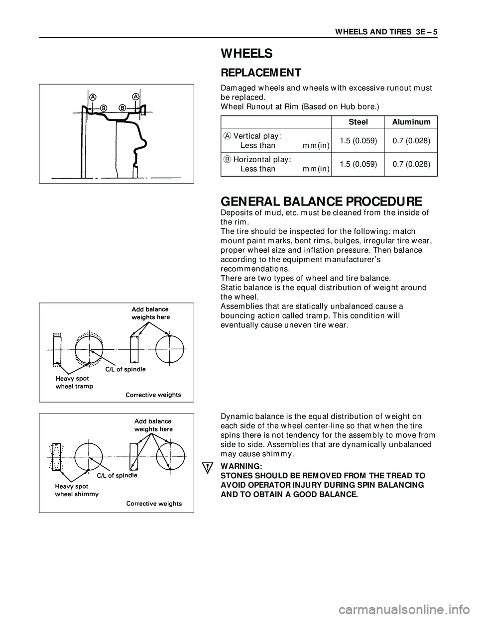
There are two types of wheel and tire balance.
Static balance is the equal distribution of weight around
the wheel.
Assemblies that are statically unbalanced cause a
bouncing action called tramp. This condition will
eventually cause uneven tire wear.
Dynamic balance is the equal distribution of weight on
each side of the wheel center-line so that when the tire
spins there is not tendency for the assembly to move from
side to side. Assemblies that are dynamically unbalanced
may cause shimmy.
WARNING:
STONES SHOULD BE REMOVED FROM THE TREAD TO
AVOID OPERATOR INJURY DURING SPIN BALANCING
AND TO OBTAIN A GOOD BALANCE.
Steel Aluminum
AVertical play:
Less than mm(in)1.5 (0.059) 0.7 (0.028)
BHorizontal play:
Less than mm(in)1.5 (0.059) 0.7 (0.028)