1998 ISUZU TROOPER door lock
[x] Cancel search: door lockPage 96 of 3573

CAUTION
When fasteners are removed, always
reinstall them at the same location from
which they were removed. If a fastener
needs to be replaced, use the correct part
number fastener for that application. If the
correct part number fastener is not available,
a fastener of equal size and strength (or
stronger) may be used. Fasteners that are not reused, and those
requiring thread locking compound, will be
called out. The correct torque values must
be used when installing fasteners that
require it. If the above conditions are not
followed, parts or system damage could
result.
HEATING AND VENTILATION 1A Ð 1
SECTION 1A
HEATING AND VENTILATION
CONTENTS
PAGE
General Description.....................................................1AÐ 2
Heater...............................................................1AÐ 2
Control Lever Assembly................................................1AÐ 3
Ventilation...........................................................1AÐ 3
Air Select Knob.......................................................1AÐ 4
Air Source Select Lever................................................1AÐ 4
Fan Control Knob.....................................................1AÐ 4
Temperature Control Knob.............................................1AÐ 4
Ceramic Heater.......................................................1AÐ 5
On-Vehicle Service......................................................1AÐ 6
Heater Unit..........................................................1AÐ 6
Heater Core and/or Mode Door..........................................1AÐ 8
Heater Mode Control Link Unit..........................................1AÐ10
Heater Temperature Control Link Unit....................................1AÐ12
Blower Assembly.....................................................1AÐ14
Blower Link Unit and/or Mode Door......................................1AÐ16
Blower Motor........................................................1AÐ18
Rear Heater Duct, Defroster Nozzle and Ventilation Duct....................1AÐ20
Center and/or Side Vent...............................................1AÐ22
Control Lever Assembly and/or Control Cables............................1AÐ24
Control Panel Illumination Bulb..........................................1AÐ27
Resistor.............................................................1AÐ28
Ceramic Heater and/or Full Hot Switch...................................1AÐ30
Page 99 of 3573

1A Ð 4 HEATING AND VENTILATION
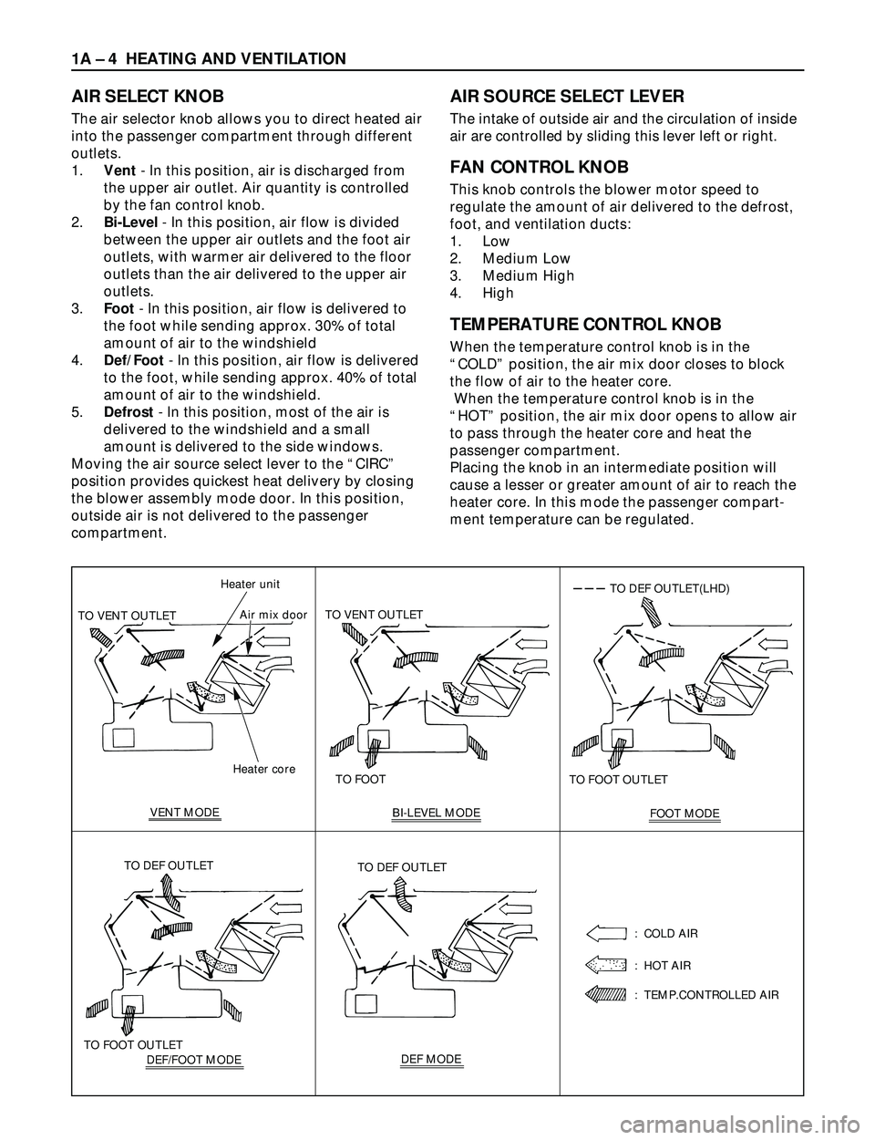
AIR SELECT KNOB
The air selector knob allows you to direct heated air
into the passenger compartment through different
outlets.
1.Vent- In this position, air is discharged from
the upper air outlet. Air quantity is controlled
by the fan control knob.
2.Bi-Level- In this position, air flow is divided
between the upper air outlets and the foot air
outlets, with warmer air delivered to the floor
outlets than the air delivered to the upper air
outlets.
3.Foot- In this position, air flow is delivered to
the foot while sending approx. 30% of total
amount of air to the windshield
4.Def/Foot- In this position, air flow is delivered
to the foot, while sending approx. 40% of total
amount of air to the windshield.
5.Defrost- In this position, most of the air is
delivered to the windshield and a small
amount is delivered to the side windows.
Moving the air source select lever to the ÒCIRCÓ
position provides quickest heat delivery by closing
the blower assembly mode door. In this position,
outside air is not delivered to the passenger
compartment.
AIR SOURCE SELECT LEVER
The intake of outside air and the circulation of inside
air are controlled by sliding this lever left or right.
FAN CONTROL KNOB
This knob controls the blower motor speed to
regulate the amount of air delivered to the defrost,
foot, and ventilation ducts:
1. Low
2. Medium Low
3. Medium High
4. High
TEMPERATURE CONTROL KNOB
When the temperature control knob is in the
ÒCOLDÓ position, the air mix door closes to block
the flow of air to the heater core.
When the temperature control knob is in the
ÒHOTÓ position, the air mix door opens to allow air
to pass through the heater core and heat the
passenger compartment.
Placing the knob in an intermediate position will
cause a lesser or greater amount of air to reach the
heater core. In this mode the passenger compart-
ment temperature can be regulated.
Heater core Heater unit
TO VENT OUTLETAir mix door
VENT MODETO FOOT TO VENT OUTLET
BI-LEVEL MODE
FOOT MODE TO FOOT OUTLET
TO DEF OUTLET(LHD)
DEF/FOOT MODE TO FOOT OUTLETTO DEF OUTLETDEF MODE TO DEF OUTLET
: COLD AIR
: HOT AIR
: TEMP.CONTROLLED AIR
Page 146 of 3573

1B Ð 20 AIR CONDITIONING
1) Make sure the evacuation process is correctly
completed.
2) Connect the center-hose of the manifold gauge to the
refrigerant container.
·Turn the charge valve handle counterclockwise to
purge the charging line and purge any air existing
in the center-hose of the manifold gauge.
3) Open the low-pressure hand valve and charge the
refrigerant about 200 g(0.44 lbs.).
·Make sure the high-pressure hand valve is closed.
·Avoid charging the refrigerant by turning the
refrigerant container upside down.
4) Close the low-pressure hand valve of the manifold
gauge.
·Check to ensure that the degree of pressure does
not charge.
5) Check the refrigerant leaks by using a HFC-134a leak
detector.
·If a leak occurs, repair the leak connection, and
start all over again from the first step of
evacuation.
6) If no leaks are found, open the low-pressure hand
valve of the manifold gauge.Then continue charging
refrigerant to the system.
·When charging the system becomes difficult:
(1) Run the engine at Idling and close the all
vehicle doors.
(2) A/C switch is ÒONÓ.
(3) Set the fan control knob (fan switch) to its
highest position.
WARNING
BE ABSOLUTELY SURE NOT TO OPEN THE HIGH-
PRESSURE HAND VALVE. SHOULD THE HIGH-
PRESSURE HAND VALVE BE OPENED, THE HIGH-
PRESSURE REFRIGERANT GAS WOULD FLOW
BACKWARD, AND THIS MAY CAUSE THE
REFRIGERANT CONTAINER TO BURST.
7) When the refrigerant container is emptied, use the
following procedure to replace it with a new
refrigerant container.
(1) Close the low pressure hand valve.
(2) Raise the needle upward and remove the charge
valve.
(3) Reinstall the charge valve to the new refrigerant
container.
(4) Purge any air existing in the center hose of the
manifold gauge.
Page 201 of 3573

AIR CONDITIONING 1BÐ75
FULL AUTO display
INTAKE indication
(LED)
(switching between
fresh and interior air)
MODE indication
(LED) (Blow port)
AC display (LED)
FAN indication (LED)
FAN KNOB
AUTO SET
REC FRESH SWITCH
TEMP LEVER
(temperature control)
MODE SWITCH
(blow port selection)
AC SWITCH
IN CAR SENSOR
AMBIENT SENSOR
SUN SENSOR
DUCT SENSOR
MIX ACTUATOR
POTENTIOMETER
MODE ACTUATOR
POTENTIOMETER
AIR MIX DOOR
MODE DOOR
INTAKE ACTUATOR
RECINTAKE DOOR
FAN MOTORPOWER
TRANSISTOR
AUTOMATIC HEATER/AIR CONDITIONER CONTROL UNIT (with the built-in micro-computer)
MAX HI RELAY
PRESSURE
SWITCHAIR CONDITIONER
THERMO RELAY
COMPRESSOR
SWITCH MAGNET
CLUTCH
PCM
PRESSURE
SWITCHAIR CONDITIONER
THERMO RELAYMAGNET
CLUTCH
(4JX1engine)
MIX FRESH
FULL AUTOMATIC AIR CONDITIONER BLOCK DIAGRAM
F01RY00009
Page 211 of 3573

AIR CONDITIONING 1BÐ85
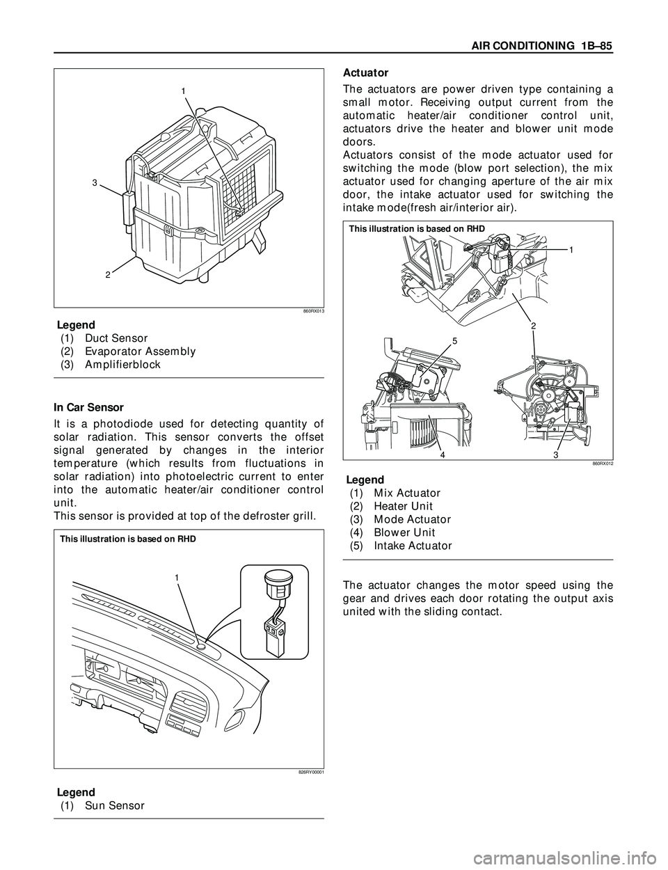
Legend
(1) Duct Sensor
(2) Evaporator Assembly
(3) Amplifierblock
In Car Sensor
It is a photodiode used for detecting quantity of
solar radiation. This sensor converts the offset
signal generated by changes in the interior
temperature (which results from fluctuations in
solar radiation) into photoelectric current to enter
into the automatic heater/air conditioner control
unit.
This sensor is provided at top of the defroster grill.
Legend
(1) Sun SensorActuator
The actuators are power driven type containing a
small motor. Receiving output current from the
automatic heater/air conditioner control unit,
actuators drive the heater and blower unit mode
doors.
Actuators consist of the mode actuator used for
switching the mode (blow port selection), the mix
actuator used for changing aperture of the air mix
door, the intake actuator used for switching the
intake mode(fresh air/interior air).
Legend
(1) Mix Actuator
(2) Heater Unit
(3) Mode Actuator
(4) Blower Unit
(5) Intake Actuator
The actuator changes the motor speed using the
gear and drives each door rotating the output axis
united with the sliding contact.
2 31
860RX013
1
826RY00001
This illustration is based on RHD
2
5
431
860RX012
This illustration is based on RHD
Page 212 of 3573

1BÐ86 AIR CONDITIONING
Legend
(1) Out put Axis
(2) Motor
(3) Printed Circuit Board
(4) Sliding Contact
The mode and mix actuators are common actuators
with the built-in potentiometer. For the intake
actuator, the contact switch type is selected.
The potentiometer is a register assembled to the
printed circuit board of the mix and mode
actuators. It detects the air mix door position
specified by rotation of the output axis as a ratio of
the variable terminal (VM) voltage against the
reference voltage (VDD: 5V), then signals the value
to the automatic heater/air conditioner control unit.¥ Movement of Mix Actuator
Position of the air mix door is determined by the
controller on the automatic heater/air conditioner
control unit.
As the heat or cool side of the controller is
grounded, the transistor on the driver is activated
and, thus, the motor rotation is turned on. The
sliding contact connected to the motor sends the
position detection signal from the potentiometer
to the automatic heater/air conditioner control
unit. As the set temperature and interior
temperature are balanced, the controller returns
to the neutral and the motor rotation is stopped.
12
43
860RW026
C01RX016
M
N 3
2
7
6
8
98 43
65 21
7
Potentiometer
ConnectionPosition
Detection
Block Automatic Heater / Air
Conditioner Control Unit
Controller
Sliding Contact
Full Heate PositionTerminal PlateFull Cool PositionDriver
Cool Side Heat Side
C01RX005
Full cool
Full cool0 0 0.5 1.0
50 100%
Aperture of air mix doorVoltage ratio VM/VDD
Full heat Full heat
VDD
VM +
–
I-45 Rotation
(+) side (Ð) side direction Remarks
8 6 Clockwise Full heat side
6 8 Counter Full cool side
clockwise
Page 213 of 3573

AIR CONDITIONING 1BÐ87
¥ Movement of Mode Actuator
As target position of the mode door is decided on
the controller of the control unit, the control unit
reads the position detection signal from the
actuator to select the clockwise or counter
clockwise motor rotation direction.
Grounding the controller VENT or DEF side after
the direction selection activates the transistor on
the driver, thus turning on the motor rotation.
Accompanying the motor rotation, the sliding
contact rotates, too. When the target position is
reached, the controller on the control unit returns
to the neutral and the motor stops.¥ Movement of Intake Actuator
The controller on the automatic heater/air
conditioner control unit selects an intake mode to
be used.
As the Terminal No.5 is grounded via the
sliding contact on the terminal plate, the
transistor on the driver is activated, thus turning
on the motor rotation. Then, accompanying
move of the motor, the sliding contact rotates
until grounding of the Terminal No.5 is
removed, thus stopping the motor.I-49
I-49
DriverController
DEF side
VENT
side
Position
detection
block Control unit
Sliding
contact
Actuator side42
983
7
78910
HLHL
HHHL
HHLL
HHLH
HLLH
HLHH
LLHH
LHHH
LHLH 61
5
Interconnected
motor
VENTVENT
Mid point between VENT - B/L
B/L
Mid point between B/L - FOOT
FOOT
Mid point between FOOT - D/F
D/F
Mid point between D/F - DEF
DEFDEF
7
8
9
10 2 6
7
8
3
4
9
5
1
C01RX017
M
+6 1 2
65 4 3
REC
MIX
FRESH
Com1
2
5
3
4++
Ð
Terminal PlateAuto A/C
Control Unit (Actuator Side)
Driver Controller
Sliding Contact
Connected
C01RX006
Conducting pin Rotation
(+) side (Ð) side direction Remarks
5 1 Clockwise VENT to
DEF direction
1 5 Counter DEF to
clockwise VENT diction
Grounding Rotation
terminal direction Remarks
No.5 Clockwise RE-CIRCULA
TION
®MIX
®FRESH I-49
Page 231 of 3573

AIR CONDITIONING 1BÐ105
Chart A: Does Not Work At All
NOFailure on the power supply circuit.
NOFailure on the actuator.
NOThe harness is disconnected.
NOReplace the automatic heater/air conditioner
control unit.
YES
YES YES
YES
Turn on the ignition switch (the engine is
started).
Switch between the fresh air intake and the
interior air circulation.
Failure on the intake link unit (intake door
lock).
Is the battery voltage present between the
chassis harness side connector terminal
No.3 and the ground?
I-49
Is the battery voltage present between
the chassis harness side connector
terminal No.4 and the ground?
I-49
Is the battery voltage present between
the chassis harness side connector
terminal No.11 and the ground?
I-32
During the above switch operations, did
the voltage between the chassis harness
side connector terminal No.11 and
the ground go below 0.5V?
I-32