1998 ISUZU TROOPER stop start
[x] Cancel search: stop startPage 2557 of 3573
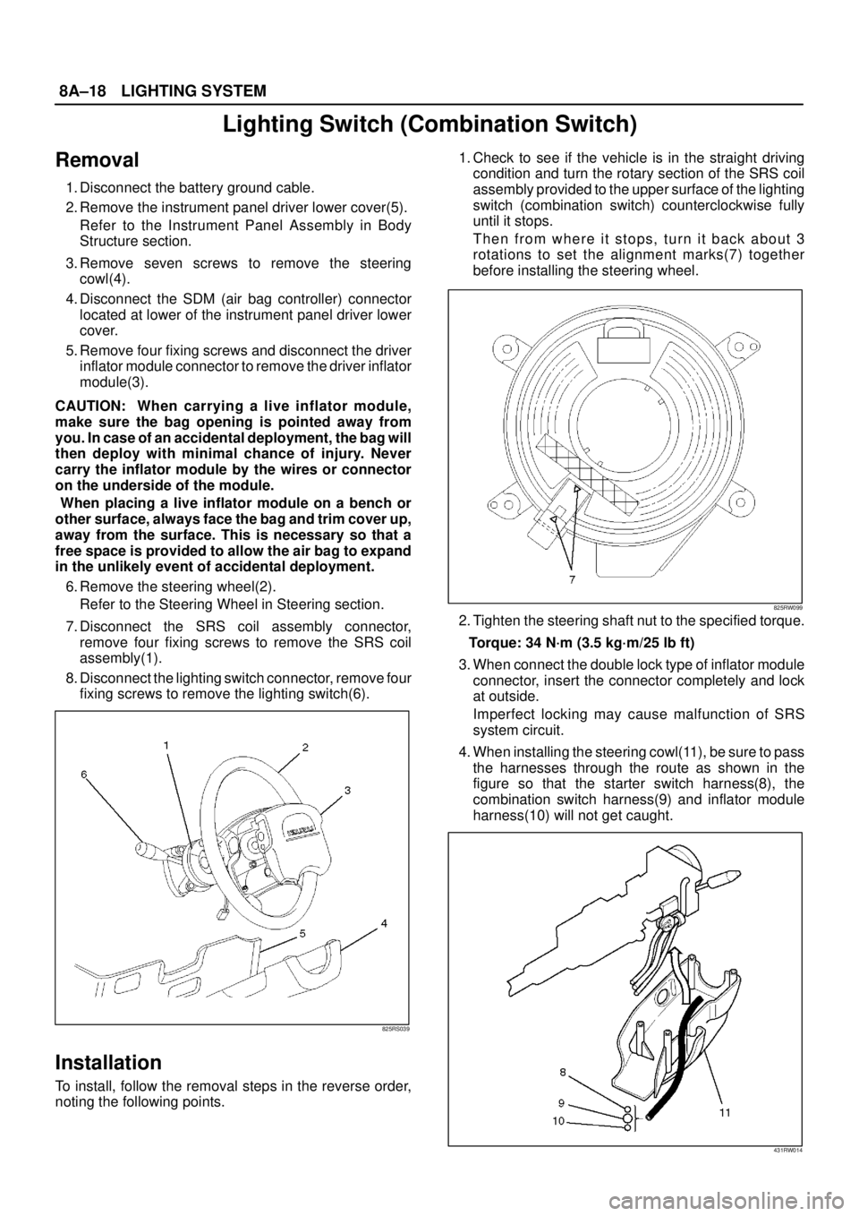
8A–18LIGHTING SYSTEM
Lighting Switch (Combination Switch)
Removal
1. Disconnect the battery ground cable.
2. Remove the instrument panel driver lower cover(5).
Refer to the Instrument Panel Assembly in Body
Structure section.
3. Remove seven screws to remove the steering
cowl(4).
4. Disconnect the SDM (air bag controller) connector
located at lower of the instrument panel driver lower
cover.
5. Remove four fixing screws and disconnect the driver
inflator module connector to remove the driver inflator
module(3).
CAUTION: When carrying a live inflator module,
make sure the bag opening is pointed away from
you. In case of an accidental deployment, the bag will
then deploy with minimal chance of injury. Never
carry the inflator module by the wires or connector
on the underside of the module.
When placing a live inflator module on a bench or
other surface, always face the bag and trim cover up,
away from the surface. This is necessary so that a
free space is provided to allow the air bag to expand
in the unlikely event of accidental deployment.
6. Remove the steering wheel(2).
Refer to the Steering Wheel in Steering section.
7. Disconnect the SRS coil assembly connector,
remove four fixing screws to remove the SRS coil
assembly(1).
8. Disconnect the lighting switch connector, remove four
fixing screws to remove the lighting switch(6).
825RS039
Installation
To install, follow the removal steps in the reverse order,
noting the following points.1. Check to see if the vehicle is in the straight driving
condition and turn the rotary section of the SRS coil
assembly provided to the upper surface of the lighting
switch (combination switch) counterclockwise fully
until it stops.
Then from where it stops, turn it back about 3
rotations to set the alignment marks(7) together
before installing the steering wheel.
825RW099
2. Tighten the steering shaft nut to the specified torque.
Torque: 34 N·m (3.5 kg·m/25 lb ft)
3. When connect the double lock type of inflator module
connector, insert the connector completely and lock
at outside.
Imperfect locking may cause malfunction of SRS
system circuit.
4. When installing the steering cowl(11), be sure to pass
the harnesses through the route as shown in the
figure so that the starter switch harness(8), the
combination switch harness(9) and inflator module
harness(10) will not get caught.
431RW014
Page 2594 of 3573
WIRING SYSTEM 8DÐ1
BODY AND ACCESSORIES
WIRING SYSTEM
CONTENTS
Service Precautions . . . . . . . . . . . . . . . . . . . 8DÐ3
General Description . . . . . . . . . . . . . . . . . . . 8DÐ4Notes for Working on Electrical Items . . 8DÐ4
Symbols and Abbreviations . . . . . . . . . . . 8DÐ10
Parts for Electrical Circuit . . . . . . . . . . . . . 8DÐ12
Reading the Circuit Diagram . . . . . . . . . . 8DÐ21
Main Data and Specifications . . . . . . . . . . . 8DÐ24 Fuse, Fusible Link and Circuit Breaker Location . . . . . . . . . . . . . . . . . . . . . . . . . . . 8DÐ24
Relay Location . . . . . . . . . . . . . . . . . . . . . . 8DÐ27
Diode Location . . . . . . . . . . . . . . . . . . . . . . 8DÐ30
Grounding Point . . . . . . . . . . . . . . . . . . . . . 8DÐ33
Cable Harness Routing . . . . . . . . . . . . . . . 8DÐ45
Fuse Block Circuit . . . . . . . . . . . . . . . . . . . . . 8DÐ53 Circuit Diagram. . . . . . . . . . . . . . . . . . . . . . 8DÐ54
Start and Charging . . . . . . . . . . . . . . . . . . . . 8DÐ67 General Description . . . . . . . . . . . . . . . . . . 8DÐ67
Circuit Diagram. . . . . . . . . . . . . . . . . . . . . . 8DÐ68
Parts Location . . . . . . . . . . . . . . . . . . . . . . . 8DÐ70
Powertrain Control Module (PCM) . . . . . . . 8DÐ80 General Description . . . . . . . . . . . . . . . . . . 8DÐ80
Circuit Diagram. . . . . . . . . . . . . . . . . . . . . . 8DÐ81
Parts Location . . . . . . . . . . . . . . . . . . . . . . . 8DÐ93
QOSIII (4JG2) . . . . . . . . . . . . . . . . . . . . . . . . . 8DÐ111 General Description . . . . . . . . . . . . . . . . . . 8DÐ111
Circuit Diagram. . . . . . . . . . . . . . . . . . . . . . 8DÐ112
Parts Location . . . . . . . . . . . . . . . . . . . . . . . 8DÐ114
QOS and EGR System (4JG2) . . . . . . . . . . . 8DÐ118 General Description . . . . . . . . . . . . . . . . . . 8DÐ118
Circuit Diagram. . . . . . . . . . . . . . . . . . . . . . 8DÐ119
Parts Location . . . . . . . . . . . . . . . . . . . . . . . 8DÐ122
Headlight and Fog Light . . . . . . . . . . . . . . . . 8DÐ127 General Description . . . . . . . . . . . . . . . . . . 8DÐ127
Circuit Diagram. . . . . . . . . . . . . . . . . . . . . . 8DÐ128
Parts Location . . . . . . . . . . . . . . . . . . . . . . . 8DÐ130
Diagnosis . . . . . . . . . . . . . . . . . . . . . . . . . . . 8DÐ134
Rear Foglight . . . . . . . . . . . . . . . . . . . . . . . . . 8DÐ150 Circuit Diagram. . . . . . . . . . . . . . . . . . . . . . 8DÐ151
Parts Location . . . . . . . . . . . . . . . . . . . . . . . 8DÐ152
Headlight Leveling . . . . . . . . . . . . . . . . . . . . 8DÐ153 General Description . . . . . . . . . . . . . . . . . . 8DÐ153
Circuit Diagram. . . . . . . . . . . . . . . . . . . . . . 8DÐ154
Parts Location . . . . . . . . . . . . . . . . . . . . . . . 8DÐ155
Diagnosis . . . . . . . . . . . . . . . . . . . . . . . . . . . 8DÐ156
Clearance Light, Taillight and License Plate Light . . . . . . . . . . . . . . . . . . . . 8DÐ159 General Description . . . . . . . . . . . . . . . . . . 8DÐ159
Circuit Diagram. . . . . . . . . . . . . . . . . . . . . . 8DÐ160
Parts Location . . . . . . . . . . . . . . . . . . . . . . . 8DÐ163
Diagnosis . . . . . . . . . . . . . . . . . . . . . . . . . . . 8DÐ168
Interior Illumination Light . . . . . . . . . . . . . . 8DÐ180 General Description . . . . . . . . . . . . . . . . . . 8DÐ180
Circuit Diagram. . . . . . . . . . . . . . . . . . . . . . 8DÐ181
Parts Location . . . . . . . . . . . . . . . . . . . . . . . 8DÐ185
Diagnosis . . . . . . . . . . . . . . . . . . . . . . . . . . . 8DÐ192
Turn Signal Light and Hazard Warning Light . . . . . . . . . . . . . . . . . . . . . . . . . . . . . . . . 8DÐ193
General Description . . . . . . . . . . . . . . . . . . 8DÐ193
Circuit Diagram. . . . . . . . . . . . . . . . . . . . . . 8DÐ194
Parts Location . . . . . . . . . . . . . . . . . . . . . . . 8DÐ197
Diagnosis . . . . . . . . . . . . . . . . . . . . . . . . . . . 8DÐ202
Stoplight . . . . . . . . . . . . . . . . . . . . . . . . . . . . . 8DÐ208 General Description . . . . . . . . . . . . . . . . . . 8DÐ208
Circuit Diagram. . . . . . . . . . . . . . . . . . . . . . 8DÐ209
Parts Location . . . . . . . . . . . . . . . . . . . . . . . 8DÐ212
Diagnosis . . . . . . . . . . . . . . . . . . . . . . . . . . . 8DÐ216
Backup Light. . . . . . . . . . . . . . . . . . . . . . . . . . 8DÐ220 General Description . . . . . . . . . . . . . . . . . . 8DÐ220
Circuit Diagram. . . . . . . . . . . . . . . . . . . . . . 8DÐ221
Parts Location . . . . . . . . . . . . . . . . . . . . . . . 8DÐ223
Diagnosis . . . . . . . . . . . . . . . . . . . . . . . . . . . 8DÐ227
Horn . . . . . . . . . . . . . . . . . . . . . . . . . . . . . . . . . 8DÐ230 General Description . . . . . . . . . . . . . . . . . . 8DÐ230
Circuit Diagram. . . . . . . . . . . . . . . . . . . . . . 8DÐ231
Parts Location . . . . . . . . . . . . . . . . . . . . . . . 8DÐ232
Diagnosis . . . . . . . . . . . . . . . . . . . . . . . . . . . 8DÐ235
Dome Light, Luggage Room Light, Courtesy Light and Map Light . . . . . . . . . . 8DÐ237
General Description . . . . . . . . . . . . . . . . . . 8DÐ237
Circuit Diagram. . . . . . . . . . . . . . . . . . . . . . 8DÐ238
Parts Location . . . . . . . . . . . . . . . . . . . . . . . 8DÐ240
Power Door Lock . . . . . . . . . . . . . . . . . . . . . . 8DÐ244 General Description . . . . . . . . . . . . . . . . . . 8DÐ244
Circuit Diagram. . . . . . . . . . . . . . . . . . . . . . 8DÐ245
Parts Location . . . . . . . . . . . . . . . . . . . . . . . 8DÐ250
Diagnosi s. . . . . . . . . . . . . . . . . . . . . . . . . . . 8DÐ2 56
Power Window . . . . . . . . . . . . . . . . . . . . . . . 8DÐ261 General Description . . . . . . . . . . . . . . . . . . 8DÐ261
Circuit Diagram. . . . . . . . . . . . . . . . . . . . . . 8DÐ262
Parts Location . . . . . . . . . . . . . . . . . . . . . . . 8DÐ263
Diagnosis . . . . . . . . . . . . . . . . . . . . . . . . . . . 8DÐ266
Cruise Control . . . . . . . . . . . . . . . . . . . . . . . . 8DÐ272
Page 2619 of 3573

8DÐ26 WIRING SYSTEM
Fuse Box
This illustration is based on RHD
C/B-1 C/B-2
C-10
C-20C-9 C-8 C-7 C-6 C-5 C-4 C-3 C-2 C-1
C-19 C-18 C-17 C-16 C-15 C-14 C-13 C-12 C-11
C-21 C-22 C-23 C-24
FUSE BOX
RHDNo.
C-1
C-2
C-3
C-4
C-5
C-6
C-7
C-8
C-9
C-10
C-11
C-12
C-13
C-14
C-15
C-16
C-17
C-18
C-19
C-20
C-21
C-22
C-23
C-24LHD
10A STARTER RELAY
15A SEAT HEATER
10A TURN, BACK
10A ELEC. IGN.
15A FRT WIPER AND WASHER
10A RR WIPER AND WASHER
10A H/LAMP WIPER
15A ENGINE
15A IGN. COIL (GASOLINE)
15A FUEL CUT (4JG2)
10A METER, GAUGE
10A AUDIO, MIRROR
20A CIGARETTE
10A ANTI-THEFT
15A STOP, A/T CONT.
20A TELEPHONE
10A CLOCK, ROOM
25A RR DEFOG.
20A DOOR LOCK
25A BLOWER
10A AIR CON.
10A SRS-110A STARTER RELAY
15A SEAT HEATER
10A TURN, BACK
10A ELEC. IGN.
15A FRT WIPER AND WASHER
10A RR WIPER AND WASHER
10A H/LAMP WIPER
15A ENGINE
15A IGN. COIL (GASOLINE)
15A FUEL CUT (4JG2)
10A METER, GAUGE
10A AUDIO, MIRROR
20A CIGARETTE
10A ANTI-THEFT
15A STOP, A/T CONT.
20A TELEPHONE
10A CLOCK, ROOM
25A RR DEFOG.
20A DOOR LOCK
25A BLOWER
10A AIR CON.
10A SRS-1 FUSE
RHDNo.
C/B-1
C/B-2LHD
30A P/W, P/S, S/R 30A P/W, P/S, S/R—— CIRCUIT BREAKER
—
—
——
—
—
810RV026
Page 2624 of 3573
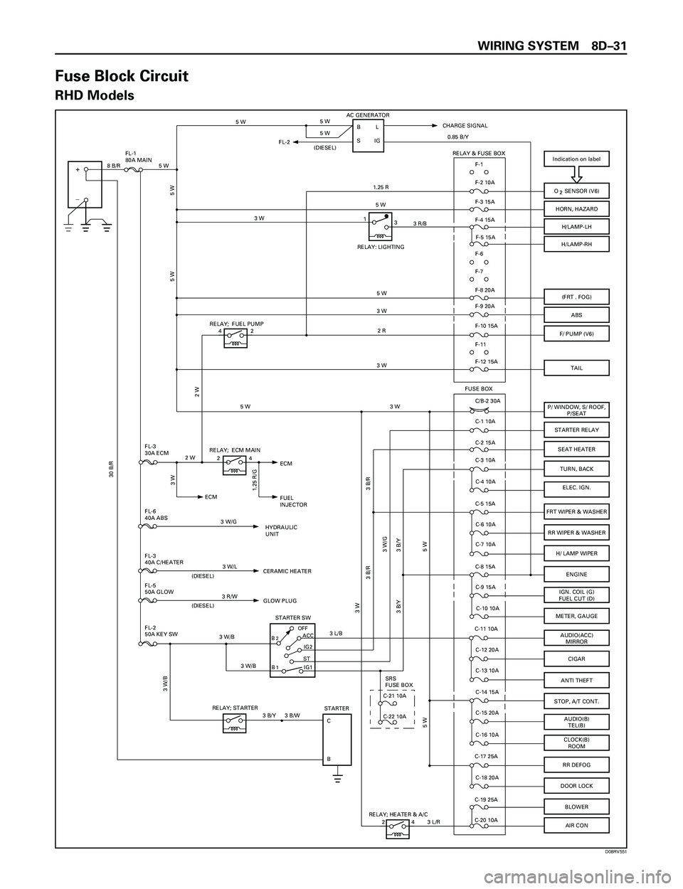
WIRING SYSTEM 8DÐ31
Fuse Block Circuit
RHD Models
Indication on label
BOFF
STIG2 ACC
STARTER SW
+
_
O SENSOR (V6)
HORN, HAZARD
H/LAMP-LH
H/LAMP-RH
(FRT . FOG)
ABS
F/ PUMP (V6)
P/ WINDOW, S/ ROOF,
P/SEAT
STARTER RELAY
TURN, BACK
ELEC. IGN.
FRT WIPER & WASHER
RR WIPER & WASHER
H/ LAMP WIPER
ENGINE
IGN. COIL (G)
FUEL CUT (D)
METER, GAUGE
AUDIO(ACC)
MIRROR
CIGAR
STOP, A/T CONT.
AUDIO(B)
TEL(B)
CLOCK(B)
ROOM
RR DEFOG
DOOR LOCK
IG1B
STARTER
C
B
AC GENERATOR
BL
IG
F-1
F-2 10A
F-3 15A
F-4 15A
F-5 15A
F-8 20A
F-9 20A
F-10 15A
C/B-2 30A
C-1 10A
C-3 10A
C-4 10A
C-5 15A
C-6 10A
C-7 10A
C-8 15A
C-9 15A
C-10 10A
C-11 10A
C-12 20A
C-14 15A
C-15 20A
C-16 10A
C-17 25A
C-18 20A RELAY; STARTERCHARGE SIGNAL
FUSE BOX
RELAY; ECM MAIN
FUEL
INJECTOR ECM
HYDRAULIC
UNIT FL-3
30A ECM
FL-6
40A ABS
FL-2
50A KEY SW FL-1
80A MAIN2
2
1
5 W
5 W
8 B/R 5 W
F-6
F-7
F-11
RELAY & FUSE BOX
C-2 15A
BLOWERC-19 25A
C-20 10A
5 W 5 W
5 W
1.25 R
5 W
5 W
3 W
2 R
3 W
3 B/R
3 W
3 W/G
3 B/Y 3 B/Y
5 W 5 W
3 B/W
3 W/B
3 W/B 3 W/B3 W/G 2 W
30 B/R
0.85 B/Y
3 L/B
3 W
1.25 R/G
SFL-2
(DIESEL)
SEAT HEATER
FL-3
40A C/HEATER
FL-5
50A GLOW
CERAMIC HEATER
(DIESEL)
GLOW PLUG
(DIESEL)
31
3 R/B3 W
24
3 W/L
3 R/W
ANTI THEFTC-13 10A
3 B/Y
RELAY: LIGHTING
3 B/R
RELAY; FUEL PUMP
42
TAIL
5 W
2 W
AIR CON
RELAY; HEATER & A/C
24
3 W
3 L/R
C-21 10ASRS
FUSE BOX
C-22 10A
F-12 15A
ECM
D08RV551
Page 2625 of 3573
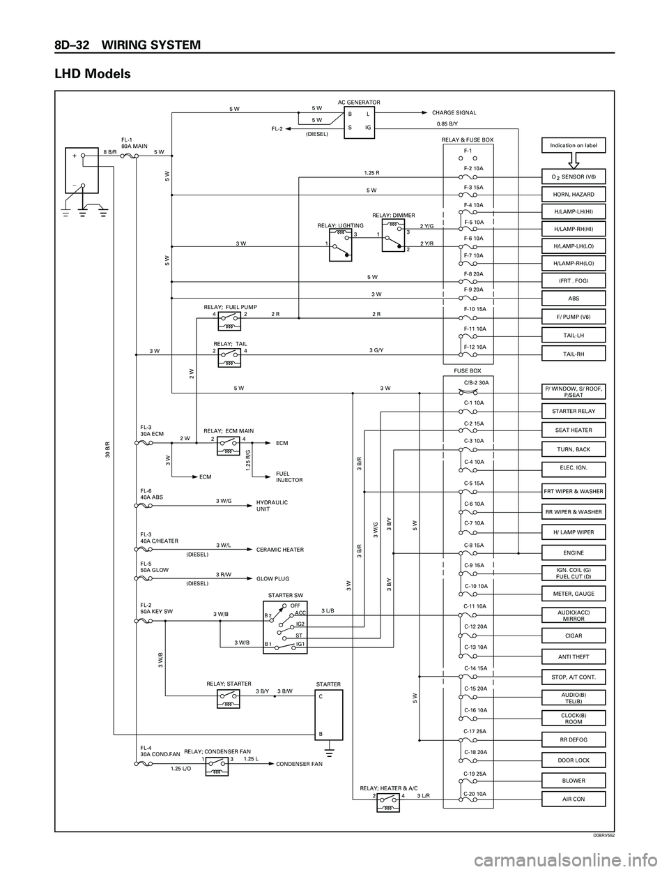
8DÐ32 WIRING SYSTEM
LHD Models
FL-4
30A COND.FAN
Indication on label
BOFF
STIG2 ACC
STARTER SW
+
_
O SENSOR (V6)
HORN, HAZARD
H/LAMP-LH(HI)
H/LAMP-RH(HI)
(FRT . FOG)
ABS
F/ PUMP (V6)
P/ WINDOW, S/ ROOF,
P/SEAT
STARTER RELAY
TURN, BACK
ELEC. IGN.
FRT WIPER & WASHER
RR WIPER & WASHER
H/ LAMP WIPER
ENGINE
IGN. COIL (G)
FUEL CUT (D)
METER, GAUGE
AUDIO(ACC)
MIRROR
CIGAR
STOP, A/T CONT.
AUDIO(B)
TEL(B)
CLOCK(B)
ROOM
RR DEFOG
DOOR LOCK
IG1B
STARTER
C
B
AC GENERATOR
BL
IG
F-1
F-2 10A
F-3 15A
F-4 10A
F-5 10A
F-8 20A
F-9 20A
F-10 15A
C/B-2 30A
C-1 10A
C-3 10A
C-4 10A
C-5 15A
C-6 10A
C-7 10A
C-8 15A
C-9 15A
C-10 10A
C-11 10A
C-12 20A
C-14 15A
C-15 20A
C-16 10A
C-17 25A
C-18 20A RELAY; STARTERCHARGE SIGNAL
FUSE BOX
RELAY; ECM MAIN
FUEL
INJECTOR ECM
HYDRAULIC
UNIT FL-3
30A ECM
FL-6
40A ABS
FL-2
50A KEY SW FL-1
80A MAIN2
2
1
ECM
5 W
5 W
8 B/R 5 W
F-6 10A
F-7 10A
F-11 10A RELAY & FUSE BOX
C-2 15A
BLOWERC-19 25A
C-20 10A
5 W 5 W
5 W
1.25 R
5 W
5 W
2 R 2 R3 W
3 B/R
3 W
3 W/G
3 B/Y 3 B/Y
5 W 5 W
3 B/W
3 W/B
3 W/B 3 W/B3 W/G 2 W
30 B/R
0.85 B/Y
3 L/B
3 W
1.25 R/G
SFL-2
(DIESEL)
SEAT HEATER
FL-3
40A C/HEATER
FL-5
50A GLOW
CERAMIC HEATER
(DIESEL)
GLOW PLUG
(DIESEL)
3 W
3 W
24
3 W/L
3 R/W
ANTI THEFTC-13 10A
3 B/Y
3 B/R
RELAY; FUEL PUMP
42
TAIL-RH
3 G/Y
5 W
2 W
AIR CON
RELAY; HEATER & A/C
24
3 W
3 L/R
F-12 10ARELAY; TAIL
24H/LAMP-LH(LO)
H/LAMP-RH(LO)
3
1
2 Y/R RELAY: DIMMER2 Y/G
2
3
1RELAY: LIGHTING
TAIL-LH
RELAY; CONDENSER FAN
131.25 L
1.25 L/O
CONDENSER FAN
D08RV552
Page 2683 of 3573
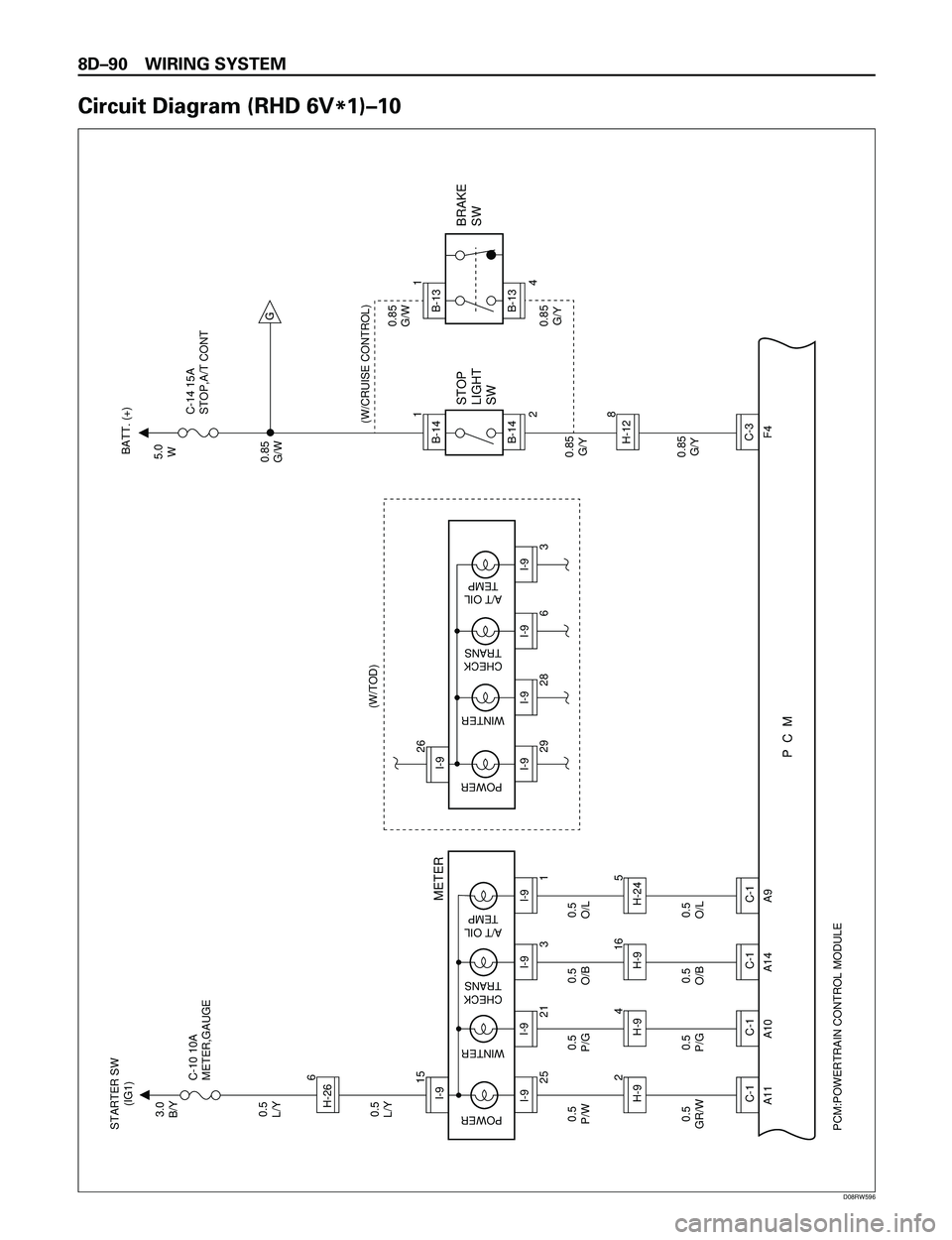
8DÐ90 WIRING SYSTEM
Circuit Diagram (RHD 6V
*1)Ð10
C-1
C-1
C-1
C-1
H-9I-9
H-9
H-9
H-24
I-9
A11 A10 A14 A9F4
PCM:POWERTRAIN CONTROL MODULE
I-9H-26
I-9
I-9
I-9
P C M
0.5
O/L0.85
G/Y 0.85
G/Y0.85
G/W 0.85
G/W5.0
W
0.85
G/Y
0.5
O/B 0.5
P/G 0.5
GR/W0.5
O/L 0.5
O/B 0.5
P/G 0.5
L/Y0.5
L/Y3.0
B/Y
0.5
P/W
5 16 4 21
I-9
29 26
I-9
28
I-9
6
I-9
B-14H-12B-14C-3 3
8 2 1
4 1
3 21 25 156 C-10 10A
METER,GAUGE STARTER SW
(IG1)
METER
POWER
WINTER
CHECK
TRANS
A/T OIL
TEMP
POWER
WINTER
CHECK
TRANS
A/T OIL
TEMP
(W/TOD)
B-13B-13G
(W/CRUISE CONTROL)
STOP
LIGHT
SWBRAKE
SWC-14 15A
STOP,A/T CONT BATT. (+)
D08RW596
Page 2698 of 3573
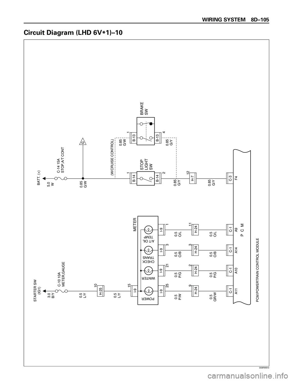
WIRING SYSTEM 8DÐ105
Circuit Diagram (LHD 6V
*1)Ð10
C-1
C-1
C-1
C-1
H-24I-9
H-24
H-24
H-24
A11 A10 A14 A9 F4
PCM:POWERTRAIN CONTROL MODULE
I-9H-25
I-9
I-9
I-9P C M0.5
O/L0.85
G/Y 0.85
G/Y0.85
G/W 0.85
G/W5.0
W
0.85
G/Y
0.5
O/B 0.5
P/G 0.5
GR/W0.5
O/L 0.5
O/B 0.5
P/G 0.5
L/Y0.5
L/Y3.0
B/Y
0.5
P/W
11 3 2 91
B-14H-7B-14C-3122 1
4 1
3 21 25 15 10C-10 10A
METER,GAUGE STARTER SW
(IG1)
METER
POWER
WINTER
CHECK
TRANS
A/T OIL
TEMP
B-13B-13G
(W/CRUISE CONTROL)
STOP
LIGHT
SWBRAKE
SWC-14 15A
STOP,A/T CONT BATT. (+)
D08RW910
Page 2867 of 3573
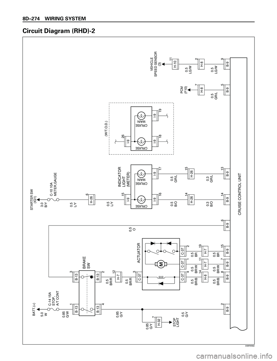
8DÐ274 WIRING SYSTEM
Circuit Diagram (RHD)-2
0.5
O
0.5
BR/B0.5
BR/R0.5
BR/R
0.5
BR/B 5.0
W
0.85
G/W
0.85
G/Y
0.5
G/Y 0.85
G/YC-14 15A
STOP,
A/T CONT
ACTUATOR BRAKE
SW
INDICATOR
LIGHT
(METER)
CRUISE CONTROL UNIT
BATT.(+)
STOP
LIGHT
2
B-9
3.0
B/Y
0.5
L/YC-10 10A
METER,GAUGE STARTER SW
(IG1)
B-131B-13
B-13H-73B-13
3C-37
7122 4
C-37
4
8B-914H-80.5
BR/W
0.5
BR/W
C-37
1
11H-70.5
BR
0.5
BR
C-37
2
19H-7
7
B-915
B-9
6
B-914
B-914H-26
H-32
0.5
L/Y
0.5
B/O
0.3
B/O0.5
GR/L
0.3
GR/L
0.5
GR/L0.5
LG/W0.5
LG/W
13
B-915H-2618
I-926I-9(W/T.O.D.)
VEHICLE
SPEED SENSOR
(3)
PCM
(F10)
19
I-9
CRUISE
CRUISE
MAIN
16
I-915I-9
17
I-9
5
B-97H-8
9
B-92H-811H-10
CRUISE
CRUISE
MAINH-266
M
D08RW662