Page 2957 of 3573
8D – 364 WIRING SYSTEM
Power Door Mirror
General Description
The circuit consists of door mirror control switch,
folding switch, defogger switch and door mirrors on
both sides.
When control switch is operated with starter switch at
either “ACC” or “ON” position, motors incorporated
in door mirrors on both sides rotates to allow the
horizontal and vertical adjustment of mirror angle.
Folding switch can be used to fold mirror and return
it to its original position.
When turning on door mirror defogger switch with
starter switch at “ON” position, built–in heater in
mirror is activated to perform defogger function.
Page 2966 of 3573
WIRING SYSTEM 8D – 373
Diagnosis
Quick Chart for Check Points
2.Mirrors on both sides do not operate
3.Mirror on the left (or right) side does
not operate
4.Mirrors on both sides operate only in
the vertical (or horizontal) direction
5.Mirror on the left side operates only
in the vertical (or horizontal) direction
6.Mirror on the right side operates only
in the vertical (or horizontal) direction
7.Folding mechanism of the both
mirrors does not operate
8.Folding mechanism of the mirror on
the left (or right) side does not operate
9.Mirror defoggers on both sides do not
operate
Mirror defogger on the left (or right)
side does not operateControl
switch
Folding
switch
Defogger
switchC-4
(10A)
C-11
(10A) SWLH RHTrouble modeCheck pointDoor mirror Door mirror SW
Cable
harness
1.
Fuse
Defogger Folding Control
Page 2967 of 3573
8D – 374 WIRING SYSTEM
1. Mirrors On Both Sides Do Not Operate
•IS THE FUSE C-11 (10A) NORMAL?
YES
•REMOVE THE CONNECTORS OF THE DOOR MIRROR CONTROL SWREPLACE THE FUSE
NO
IS THERE ANY CONTINUITY BETWEEN THE HARNESS
SIDE CONNECTORS 9 B-55 AND THE GROUND?
•SET THE STARTER SW TO “ACC” POSITION
•IS THE BATTERY VOLTAGE APPLIED BETWEEN THE HARNESS
SIDE CONNECTOR 4 B-55 AND THE GROUND?
YESNO
•REPAIR A POOR CONNECTION AT THE CONNECTORS
OR AN OPEN CIRCUIT BETWEEN THE FUSE C-11 (10A)
AND 4 B-55 (CONTROL SW)
YESNO
REPAIR A POOR CONNECTION AT THE CONNECTORS
OR AN OPEN CIRCUIT IN THE CIRCUIT
YESNO
REPAIR THE DOOR MIRROR CONTROL SW REPAIR A POOR CONNECTION AT THE CONNECTORS OR
AN OPEN CIRCUIT BETWEEN 1 B-55 AND 18 H-18 OR
18 H-22
IS THE CONTINUITY IN THE DOOR MIRROR CONTROL
SWITCH NORMAL?•
Page 2968 of 3573

WIRING SYSTEM 8D – 375
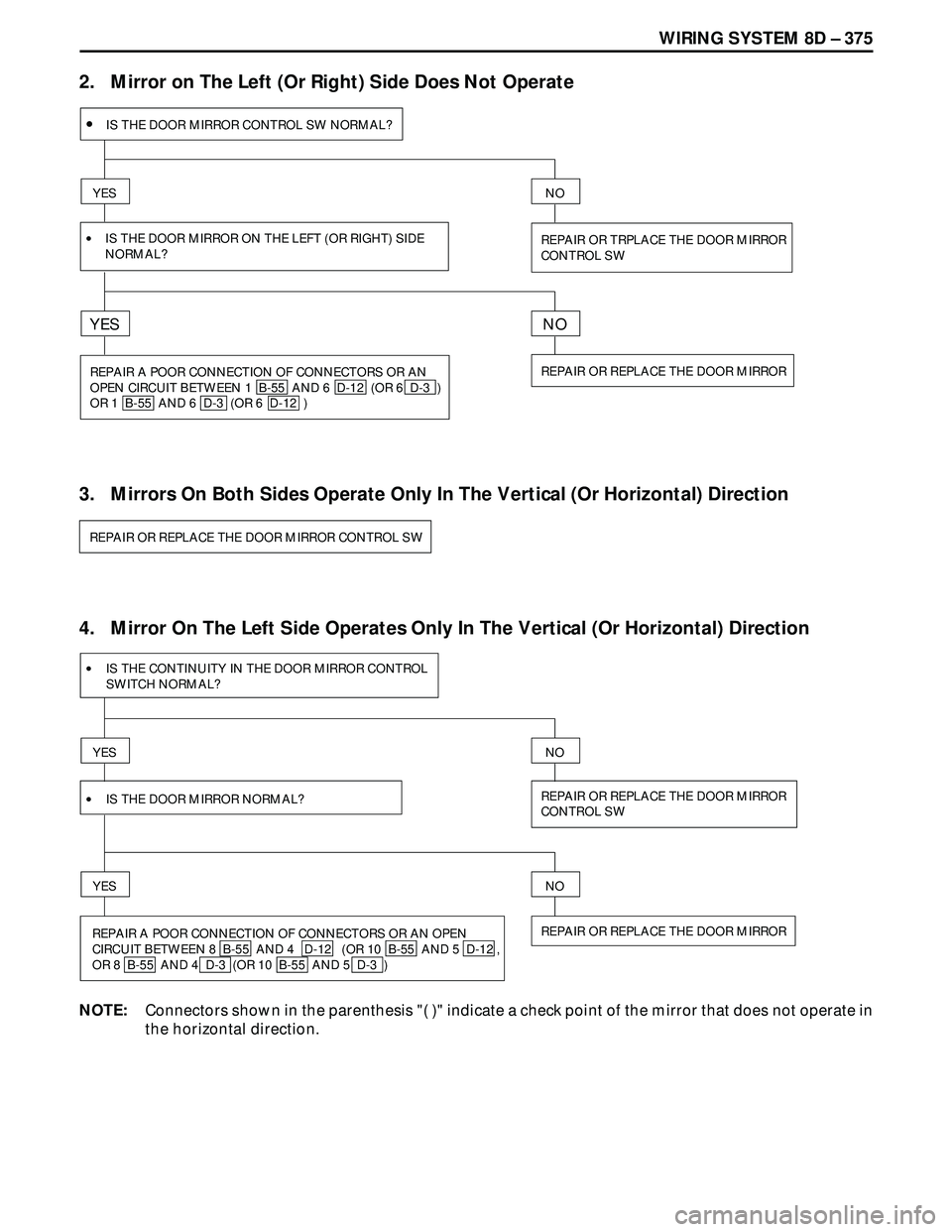
2. Mirror on The Left (Or Right) Side Does Not Operate
4. Mirror On The Left Side Operates Only In The Vertical (Or Horizontal) Direction
•IS THE DOOR MIRROR CONTROL SW NORMAL?
YES
REPAIR OR TRPLACE THE DOOR MIRROR
CONTROL SW
NO
REPAIR OR REPLACE THE DOOR MIRROR
IS THE DOOR MIRROR ON THE LEFT (OR RIGHT) SIDE
NORMAL?
YESNO
REPAIR A POOR CONNECTION OF CONNECTORS OR AN
OPEN CIRCUIT BETWEEN 1 B-55 AND 6 D-12 (OR 6 D-3 )
OR 1 B-55 AND 6 D-3 (OR 6 D-12 ) •
3. Mirrors On Both Sides Operate Only In The Vertical (Or Horizontal) Direction
REPAIR OR REPLACE THE DOOR MIRROR CONTROL SW
•IS THE CONTINUITY IN THE DOOR MIRROR CONTROL
SWITCH NORMAL?
YES
YES
REPAIR OR REPLACE THE DOOR MIRROR
CONTROL SW
NO
NO
•IS THE DOOR MIRROR NORMAL?
REPAIR A POOR CONNECTION OF CONNECTORS OR AN OPEN
CIRCUIT BETWEEN 8 B-55 AND 4 D-12 (OR 10 B-55 AND 5 D-12 ,
OR 8 B-55 AND 4 D-3 (OR 10 B-55 AND 5 D-3 )REPAIR OR REPLACE THE DOOR MIRROR
NOTE:Connectors shown in the parenthesis "( )" indicate a check point of the mirror that does not operate in
the horizontal direction.
Page 2969 of 3573
8D – 376 WIRING SYSTEM
5. Mirror On The Right Side Operates Only In The Vertical (Or Horizontal) Direction
6. Folding Mechanism Of The Both Mirrors Does Not Operate
•IS THE CONTINUITY IN THE DOOR MIRROR
CONTROL SWITCH NORMAL?
YES
REPAIR A POOR CONNECTION OF CONNECTORS OR AN OPEN
CIRCUIT BETWEEN 7 B-55 AND 4 D-3 (OR 5 B-55 AND 5 D-3 ),
OR 7 B-55 AND 4 D-12 (OR 5 B-55 AND 5 D-12 )
YES
REPAIR OR REPLACE THE DOOR MIRROR SWITCH
NO
NO
•IS THE DOOR MIRROR NORMAL?
REPAIR OR REPLACE THE DOOR MIRROR
NOTE:Connectors shown in the parenthesis "( )" indicate a check point of the mirror that does not operate in
the horizontal direction.
•IS THE FUSE C-11 (10A) NORMAL?
YES
YES
REPLACE THE FUSE
NO
NO
•IS THE CONTINUITY IN THE DOOR MIRROR
FOLDING SW NORMAL?
REPAIR A POOR CONNECTION AT THE CONNECTORS OR AN OPEN
CIRCUIT BETWEEN 4 B-56 AND 16 H-22 (OR 16 H-18 ) OR 7 B-56
AND 17 H-22 (OR 17 H-18 )REPAIR OR REPLACE THE DOOR MIRROR
FOLDING SW
Page 3417 of 3573

8J±38EXTERIOR/INTERIOR TRIM
Power Door Mirror System
General Description
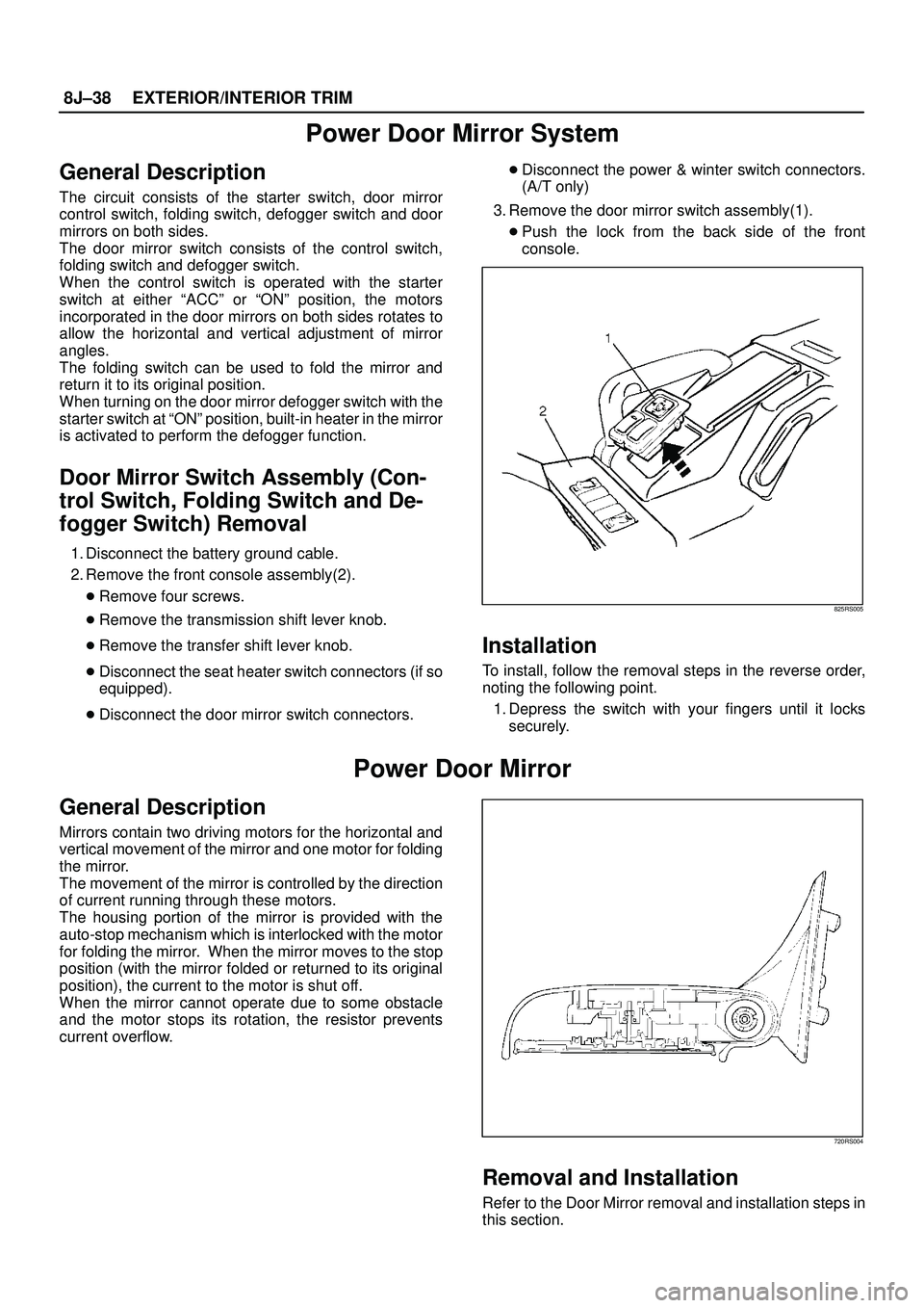
The circuit consists of the starter switch, door mirror
control switch, folding switch, defogger switch and door
mirrors on both sides.
The door mirror switch consists of the control switch,
folding switch and defogger switch.
When the control switch is operated with the starter
switch at either ªACCº or ªONº position, the motors
incorporated in the door mirrors on both sides rotates to
allow the horizontal and vertical adjustment of mirror
angles.
The folding switch can be used to fold the mirror and
return it to its original position.
When turning on the door mirror defogger switch with the
starter switch at ªONº position, built-in heater in the mirror
is activated to perform the defogger function.
Door Mirror Switch Assembly (Con-
trol Switch, Folding Switch and De-
fogger Switch) Removal
1. Disconnect the battery ground cable.
2. Remove the front console assembly(2).
�Remove four screws.
�Remove the transmission shift lever knob.
�Remove the transfer shift lever knob.
�Disconnect the seat heater switch connectors (if so
equipped).
�Disconnect the door mirror switch connectors.�Disconnect the power & winter switch connectors.
(A/T only)
3. Remove the door mirror switch assembly(1).
�Push the lock from the back side of the front
console.
825RS005
Installation
To install, follow the removal steps in the reverse order,
noting the following point.
1. Depress the switch with your fingers until it locks
securely.
Power Door Mirror
General Description
Mirrors contain two driving motors for the horizontal and
vertical movement of the mirror and one motor for folding
the mirror.
The movement of the mirror is controlled by the direction
of current running through these motors.
The housing portion of the mirror is provided with the
auto-stop mechanism which is interlocked with the motor
for folding the mirror. When the mirror moves to the stop
position (with the mirror folded or returned to its original
position), the current to the motor is shut off.
When the mirror cannot operate due to some obstacle
and the motor stops its rotation, the resistor prevents
current overflow.
720RS004
Removal and Installation
Refer to the Door Mirror removal and installation steps in
this section.