1998 ISUZU TROOPER check engine light
[x] Cancel search: check engine lightPage 147 of 3573

AIR CONDITIONING 1B Ð 21
8) Charge the system to the specified amount and then
close the low-pressure hand valve.
Refrigerant Amount g(lbs.)
750 (1.65)
DELPH1HD6/HT6 g(lbs.)
600 (1.32)
·A fully charged system is indicated by the sight
glass on the receiver/driver being free of any.
bubbles(Refer to ÒReading Sight GlassÓ).
·Check the high and low pressure value of the
manifold gauge.
·Check for refrigerant leaks by using a HFC-134a
leak detector.
Immediately after charging refrigerant, both high and low
pressures are slightly high and to the left of the gauge, but
they settle down to the guide pressure valves as shown
below:
·Ambient temperature; 25 ~30¡C (77 ~86¡F)
·Guide pressure
High-pressure side;
Approx. 1373 Ð 1863 kPa (14 Ð 19 kgácm
2/ 199 Ð 270 PSI)
Low-pressure side;
Approx. 147 Ð 294 kPa (1.4 Ð 3.0 kgácm
2/ 21 Ð 43 PSI)
9) Close the low pressure hand valve and charge valve
of the refrigerant container.
10) Stop the air conditioning and the engine.
11) Disconnect the high and low pressure hoses from the
manifold gauge fittings.
Page 148 of 3573

1B Ð 22 AIR CONDITIONING
Almost transparent.
A flow of bubbles
can be seen, but
they disappear
when the throttle is
opened.
The sight glass provides accurate diagnosis only under the following conditions.
If the vehicle can be tested under these conditions, check the sight glass appearance and compare to the
chart.
* Engine speed Idling
* A/C switch ÒONÓ
* Blower fan operating at highest speed
* Air source selector lever at ÒRECIRCÓ
* Temperature control knob at coldest position
* Ambient temperature below 30¡C (86¡F) and humidity below 70% (See NOTE 1)
* High side pressure less than 1863 kPa (19 kgácm
2/ 270 PSI) (See NOTE 2)
NOTE 1
If the vehicle cannot be moved to a testing location that meets these specifications, then the sight glass
cannot be used for diagnosis. You must discharge and recover the refrigerant, then recharge the system
with the specified amount of refrigerant. Then continue checking the system performance.
NOTE 2
If the high side pressure is greater than stated, the sight glass cannot be used for diagnosis. You must
discharge and recover the refrigerant, then recharge the system with the specified amount of refrigerant.
Then continue checking system performance.
Reading Sight Glass
High and low
pressure pipe
temperature
Sight glass
condition
Air condi-
tioner cycle
condition
The high pressure
pipe is hot and the
low pressure pipe is
cold. There is a dis-
tinct difference in
temperature bet-
ween them.
OK
The high pressure
pipe is warm and
the low pressure
pipe is cool. There
is no great dif-
ference in tempera-
ture between them.
A flow of bubbles
always can be seen.
It appears some-
times transparent,
and sometimes
frothy.
NG
(Not enough
refrigerant)
There is little dif-
ference in tempera-
ture between the
high pressure pipe
and the low press-
ure pipe.
Something like fog
faintly can be seen.
NG
(Almost no
refrigerant)
The high pressure
pipe is hot and the
low pressure pipe is
slightly warm.
There is a difference
in temperature bet-
ween them.
Even at idle with the
fan at ÒHIÓ (with the
window fully open),
the bubbles cannot
be seen.
NG
(Too much
refrigerant)
Page 220 of 3573
1BÐ94 AIR CONDITIONING
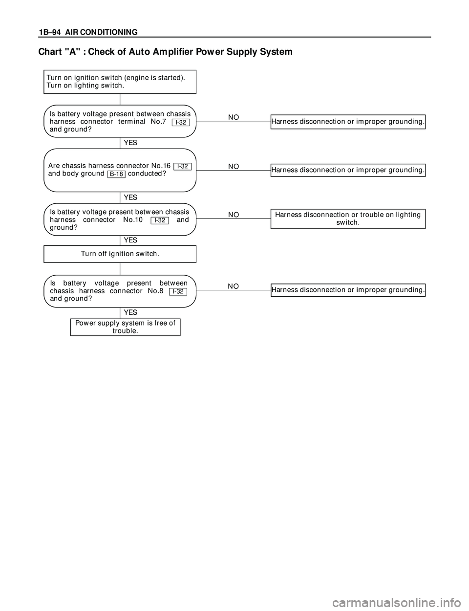
Chart "A" : Check of Auto Amplifier Power Supply System
NOHarness disconnection or improper grounding.
NOHarness disconnection or improper grounding.
NOHarness disconnection or trouble on lighting
switch.
NOHarness disconnection or improper grounding.
Turn off ignition switch.
Power supply system is free of
trouble.
YES YES
YES YES
Is battery voltage present between chassis
harness connector terminal No.7
and ground?
I-32
Is battery voltage present between
chassis harness connector No.8
and ground?
I-32
Are chassis harness connector No.16
and body ground conducted?
B-18I-32
Turn on ignition switch (engine is started).
Turn on lighting switch.
Is battery voltage present between chassis
harness connector No.10 and
ground?
I-32
Page 224 of 3573
1BÐ98 AIR CONDITIONING
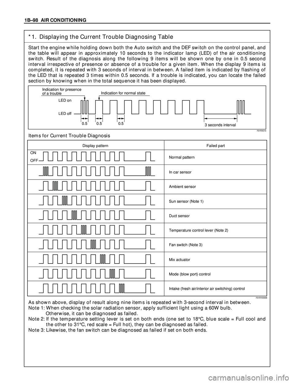
*1. Displaying the Current Trouble Diagnosing Table
Start the engine while holding down both the Auto switch and the DEF switch on the control panel, and
the table will appear in approximately 10 seconds to the indicator lamp (LED) of the air conditioning
switch. Result of the diagnosis along the following 9 items will be shown one by one in 0.5 second
interval irrespective of presence or absence of a trouble for a given item. When the display 9 items is
completed, it is repeated with 3 seconds of interval in between. A failed item is indicated by flashing of
the LED that is repeated 3 times within 0.5 seconds. If a trouble is indicated, you can locate the failed
section by knowing when in the total sequence it has been displayed.
Items for Current Trouble Diagnosis
As shown above, display of result along nine items is repeated with 3-second interval in between.
Note 1: When checking the solar radiation sensor, apply sufficient light using a 60W bulb.
Otherwise, it can be diagnosed as failed.
Note 2: If the temperature setting lever is set on both ends (one set to 18¡C, blue scale = Full cool and
the other to 31¡C, red scale = Full hot), they can be diagnosed as failed.
Note 3: Likewise, the fan switch can be diagnosed as failed if set on both ends.
LED on
LED off Indication for presence
of a troubleIndication for normal state
0.5 0.5 0.5
3 seconds interval
ON
OFF
Display pattern Failed part
Normal pattern
In car sensor
Ambient sensor
Sun sensor (Note 1)
Duct sensor
Temperature control lever (Note 2)
Fan switch (Note 3)
Mix actuator
Mode (blow port) control
Intake (fresh air/interior air switching) control
F01RX010
F01RY00008
Page 314 of 3573
BLEEDING THE POWER
STEERING SYSTEM
When a power steering pump or gear has been
installed, or an oil line has been disconnected, the
air that has entered the system must be bled out
before the vehicle is operated. If air is allowed to
remain in the power steering fluid system, noisy
and unsatisfactory operation of the system may
result.
BLEEDING PROCEDURE
When bleeding the system, and any time fluid is
added to the power steering system, be sure to use
only power steering fluid as specified in
“MAINTENANCE AND LUBRICATION” in section
0B.
1. Fill the pump fluid reservoir to the proper
level and let the fluid settle for at least two
minutes.
2. Start the engine and let it run for a few
seconds.
Do not turn the steering wheel. Then turn the
engine off.
3. Add fluid if necessary.
4. Repeat the above procedure until the fluid
level remains constant after running the
engine.
5. Raise the front end of the vehicle so that the
wheels are off the ground.
6. Start the engine. Slowly turn the steering
wheel right and left, lightly contacting the
wheel stops.
7. Add power steering fluid if necessary.
8. Bring down the vehicle, set the steering wheel
at the straight forward position after turning it
to its full steer positions 2 or 3 times, and stop
the engine.
9. Stop the engine. Check the fluid level and
refill as required.
10. If the fluid is extremely foamy, allow the
vehicle to stand a few minutes and repeat the
above procedure.
INSPECT
•Belt for tightness.
•Pulley for looseness or damage. The pulley
should not wobble with the engine running.
•Make sure that hose and pipes are properly
fitted.
•Fluid level and fill to the proper level.
FLUSHING THE POWER
STEERING SYSTEM
1. Raise the front end of the vehicle off the
ground until the wheels are free to turn.
2. Remove the fluid return line at the reservoir
inlet connector and plug the connector.
Position the line toward a large container to
catch the draining fluid.
3. While running the engine at idle, fill the
reservoir with new power steering fluid. Turn
the steering wheel in both directions. Do not
contact wheel stops or hold the wheel in a
corner, or fluid will stop and the pump will be
in pressure relief mode. A sudden overflow
from the reservoir may develop if the wheel is
held at a stop.
4. While refilling the reservoir, check the
draining fluid for contamination. If foreign
material is still evident, replace all lines,
disassemble and clean or replace the power
steering system components. Do not re-use
any drained power steering fluid.
5. Install all the lines and hoses. Fill the system
with new power steering fluid and bleed the
system as described in “Bleeding The Power
Steering System”. Operate the engine for
about 15 minutes. 2A – 12 POWER STEERING
ON-VEHICLE SERVICE
Page 470 of 3573
DIFFERENTIAL (REAR 220mm)
4A2A±3
Diagnosis
Many noises that seem to come from the rear axle
actually originate from other sources such as tires, road
surface, wheel bearings, engine, transmission, muffler, or
body drumming. Investigate to find the source of the
noise before disassembling the rear axle. Rear axles, like
any other mechanical device, are not absolutely quiet but
should be considered quiet unless some abnormal noise
is present.
To make a systematic check for axle noise, observe the
following:
1. Select a level asphalt road to reduce tire noise and
body drumming.
2. Check rear axle lubricant level to assure correct level,
and then drive the vehicle far enough to thoroughly
warm up the rear axle lubricant.
3. Note the speed at which noise occurs. Stop the
vehicle and put the transmission in neutral. Run the
engine speed slowly up and down to determine if the
noise is caused by exhaust, muffler noise, or other
engine conditions.
4. Tire noise changes with different road surfaces; axle
noises do not. Temporarily inflate all tires to 344 kPa
(3.5kg/cm
2, 50 psi) (for test purposes only). This will
change noise caused by tires but will not affect noise
caused by the rear axle.
Rear axle noise usually stops when coasting at
speeds under 48 km/h (30 mph); however, tire noise
continues with a lower tone. Rear axle noise usually
changes when comparing pull and coast, but tire
noise stays about the same.
Distinguish between tire noise and rear axle noise by
noting if the noise changes with various speeds or
sudden acceleration and deceleration. Exhaust and
axle noise vary under these conditions, while tire
noise remains constant and is more pronounced at
speeds of 32 to 48 km/h (20 to 30 mph). Further check
for tire noise by driving the vehicle over smooth
pavements or dirt roads (not gravel) with the tires at
normal pressure. If the noise is caused by tires, it will
change noticeably with changes in road surface.
5. Loose or rough front wheel bearings will cause noise
which may be confused with rear axle noise; however,
front wheel bearing noise does not change when
comparing drive and coast. Light application of the
brake while holding vehicle speed steady will often
cause wheel bearing noise to diminish. Front wheel
bearings may be checked for noise by jacking up the
wheels and spinning them or by shaking the wheels to
determine if bearings are loose.
6. Rear suspension rubber bushings and spring
insulators dampen out rear axle noise when correctly
installed. Check to see that there is no link or rod
loosened or metal±to±metal contact.
7. Make sure that there is no metal±to±metal contact
between the floor and the frame.
After the noise has been determined to be in the axle, the
type of axle noise should be determined, in order to make
any necessary repairs.
Gear Noise
Gear noise (whine) is audible from 32 to 89 km/h (20 to 55
mph) under four driving conditions.
1. Driving under acceleration or heavy pull.
2. Driving under load or under constant speed.
3. When using enough throttle to keep the vehicle from
driving the engine while the vehicle slows down
gradually (engine still pulls slightly).
4. When coasting with the vehicle in gear and the throttle
closed. The gear noise is usually more noticeable
between 48 and 64 km/h (30 and 40 mph) and 80 and
89 km/h (50 and 55 mph).
Bearing Noise
Bad bearings generally produce a rough growl or grating
sound, rather than the whine typical of gear noise.
Bearing noise frequently ªwow±wowsº at bearing rpm,
indicating a bad pinion or rear axle side bearing. This
noise can be confused with rear wheel bearing noise.
Rear Wheel Bearing Noise
Rear wheel bearing noise continues to be heard while
coasting at low speed with transmission in neutral. Noise
may diminish by gentle braking. Jack up the rear wheels,
spin them by hand and listen for noise at the hubs.
Replace any faulty wheel bearings.
Knock At Low Speeds
Low speed knock can be caused by worn universal joints
or a side gear hub counter bore in the cage that is worn
oversize. Inspect and replace universal joints or cage and
side gears as required.
Backlash Clunk
Excessive clunk on acceleration and deceleration can be
caused by a worn rear axle pinion shaft, a worn cage,
excessive clearance between the axle and the side gear
splines, excessive clearance between the side gear hub
and the counterbore in the cage, worn pinion and side
gear teeth, worn thrust washers, or excessive drive pinion
and ring gear backlash. Remove worn parts and replace
as required. Select close±fitting parts when possible.
Adjust pinion and ring gear backlash.
Page 506 of 3573
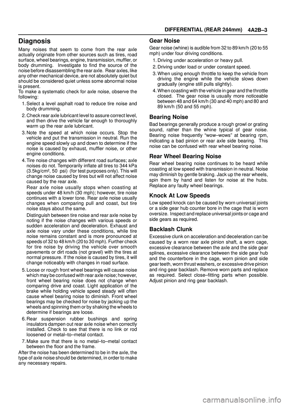
DIFFERENTIAL (REAR 244mm)
4A2B±3
Diagnosis
Many noises that seem to come from the rear axle
actually originate from other sources such as tires, road
surface, wheel bearings, engine, transmission, muffler, or
body drumming. Investigate to find the source of the
noise before disassembling the rear axle. Rear axles, like
any other mechanical device, are not absolutely quiet but
should be considered quiet unless some abnormal noise
is present.
To make a systematic check for axle noise, observe the
following:
1. Select a level asphalt road to reduce tire noise and
body drumming.
2. Check rear axle lubricant level to assure correct level,
and then drive the vehicle far enough to thoroughly
warm up the rear axle lubricant.
3. Note the speed at which noise occurs. Stop the
vehicle and put the transmission in neutral. Run the
engine speed slowly up and down to determine if the
noise is caused by exhaust, muffler noise, or other
engine conditions.
4. Tire noise changes with different road surfaces; axle
noises do not. Temporarily inflate all tires to 344 kPa
(3.5kg/cm
2, 50 psi) (for test purposes only). This will
change noise caused by tires but will not affect noise
caused by the rear axle.
Rear axle noise usually stops when coasting at
speeds under 48 km/h (30 mph); however, tire noise
continues with a lower tone. Rear axle noise usually
changes when comparing pull and coast, but tire
noise stays about the same.
Distinguish between tire noise and rear axle noise by
noting if the noise changes with various speeds or
sudden acceleration and deceleration. Exhaust and
axle noise vary under these conditions, while tire
noise remains constant and is more pronounced at
speeds of 32 to 48 km/h (20 to 30 mph). Further check
for tire noise by driving the vehicle over smooth
pavements or dirt roads (not gravel) with the tires at
normal pressure. If the noise is caused by tires, it will
change noticeably with changes in road surface.
5. Loose or rough front wheel bearings will cause noise
which may be confused with rear axle noise; however,
front wheel bearing noise does not change when
comparing drive and coast. Light application of the
brake while holding vehicle speed steady will often
cause wheel bearing noise to diminish. Front wheel
bearings may be checked for noise by jacking up the
wheels and spinning them or by shaking the wheels to
determine if bearings are loose.
6. Rear suspension rubber bushings and spring
insulators dampen out rear axle noise when correctly
installed. Check to see that there is no link or rod
loosened or metal±to±metal contact.
7. Make sure that there is no metal±to±metal contact
between the floor and the frame.
After the noise has been determined to be in the axle, the
type of axle noise should be determined, in order to make
any necessary repairs.
Gear Noise
Gear noise (whine) is audible from 32 to 89 km/h (20 to 55
mph) under four driving conditions.
1. Driving under acceleration or heavy pull.
2. Driving under load or under constant speed.
3. When using enough throttle to keep the vehicle from
driving the engine while the vehicle slows down
gradually (engine still pulls slightly).
4. When coasting with the vehicle in gear and the throttle
closed. The gear noise is usually more noticeable
between 48 and 64 km/h (30 and 40 mph) and 80 and
89 km/h (50 and 55 mph).
Bearing Noise
Bad bearings generally produce a rough growl or grating
sound, rather than the whine typical of gear noise.
Bearing noise frequently ªwow±wowsº at bearing rpm,
indicating a bad pinion or rear axle side bearing. This
noise can be confused with rear wheel bearing noise.
Rear Wheel Bearing Noise
Rear wheel bearing noise continues to be heard while
coasting at low speed with transmission in neutral. Noise
may diminish by gentle braking. Jack up the rear wheels,
spin them by hand and listen for noise at the hubs.
Replace any faulty wheel bearings.
Knock At Low Speeds
Low speed knock can be caused by worn universal joints
or a side gear hub counter bore in the cage that is worn
oversize. Inspect and replace universal joints or cage and
side gears as required.
Backlash Clunk
Excessive clunk on acceleration and deceleration can be
caused by a worn rear axle pinion shaft, a worn cage,
excessive clearance between the axle and the side gear
splines, excessive clearance between the side gear hub
and the counterbore in the cage, worn pinion and side
gear teeth, worn thrust washers, or excessive drive pinion
and ring gear backlash. Remove worn parts and replace
as required. Select close±fitting parts when possible.
Adjust pinion and ring gear backlash.
Page 558 of 3573
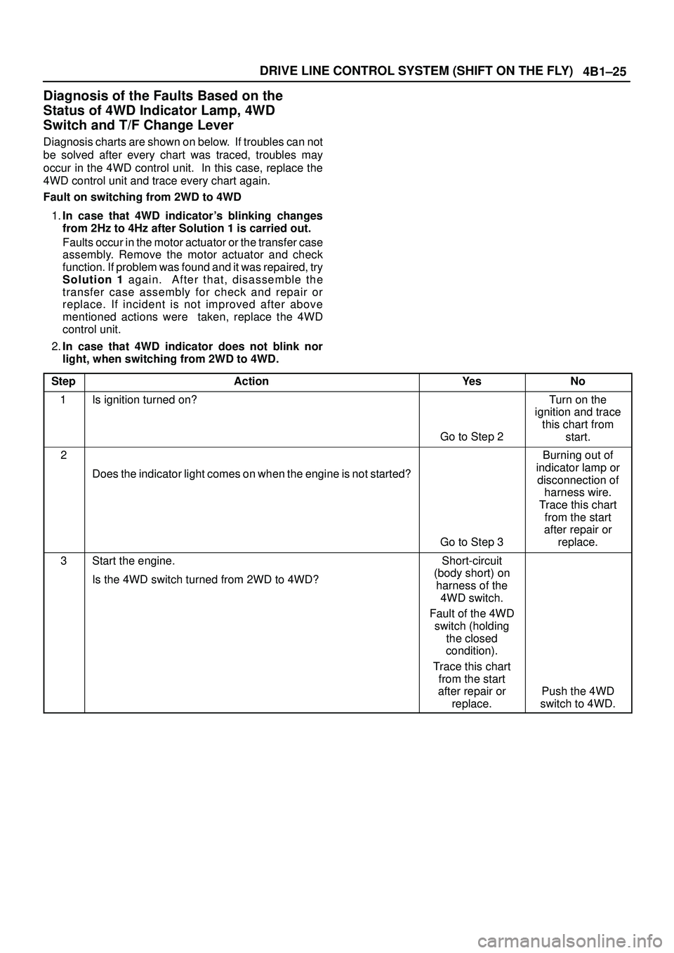
4B1±25 DRIVE LINE CONTROL SYSTEM (SHIFT ON THE FLY)
Diagnosis of the Faults Based on the
Status of 4WD Indicator Lamp, 4WD
Switch and T/F Change Lever
Diagnosis charts are shown on below. If troubles can not
be solved after every chart was traced, troubles may
occur in the 4WD control unit. In this case, replace the
4WD control unit and trace every chart again.
Fault on switching from 2WD to 4WD
1.In case that 4WD indicator's blinking changes
from 2Hz to 4Hz after Solution 1 is carried out.
Faults occur in the motor actuator or the transfer case
assembly. Remove the motor actuator and check
function. If problem was found and it was repaired, try
Solution 1 again. After that, disassemble the
transfer case assembly for check and repair or
replace. If incident is not improved after above
mentioned actions were taken, replace the 4WD
control unit.
2.In case that 4WD indicator does not blink nor
light, when switching from 2WD to 4WD.
Step
ActionYe sNo
1Is ignition turned on?
Go to Step 2
Turn on the
ignition and trace
this chart from
start.
2
Does the indicator light comes on when the engine is not started?
Go to Step 3
Burning out of
indicator lamp or
disconnection of
harness wire.
Trace this chart
from the start
after repair or
replace.
3Start the engine.
Is the 4WD switch turned from 2WD to 4WD?Short-circuit
(body short) on
harness of the
4WD switch.
Fault of the 4WD
switch (holding
the closed
condition).
Trace this chart
from the start
after repair or
replace.
Push the 4WD
switch to 4WD.