Page 1889 of 3573
6D – 22 ENGINE ELECTRICAL
1. Using a press with a socket wrench attached,
reassemble rotor and rear end cover assembly in
the front cover.2. Install pulley on the rotor.
Secure the pulley directly in the vise between two
copper plates, and tighten nut to the specified
torque.
Torque: 111 N·m (82 lb ft)
066RS022
066RS010
MAIN DATA AND SPECIFICATIONS
General Specifications
Model LR190-750B LR-1100-731
Battery voltage V 12
Rated output A 90 100
Direction of rotation Clockwise
(as viewed from pulley side)
Rated rotation speed rpm 5,000
Maximum speed rpm 18,000
Page 2221 of 3573

7A±67 AUTOMATIC TRANSMISSION (4L30±E)
Sprag Unit
Disassembled View
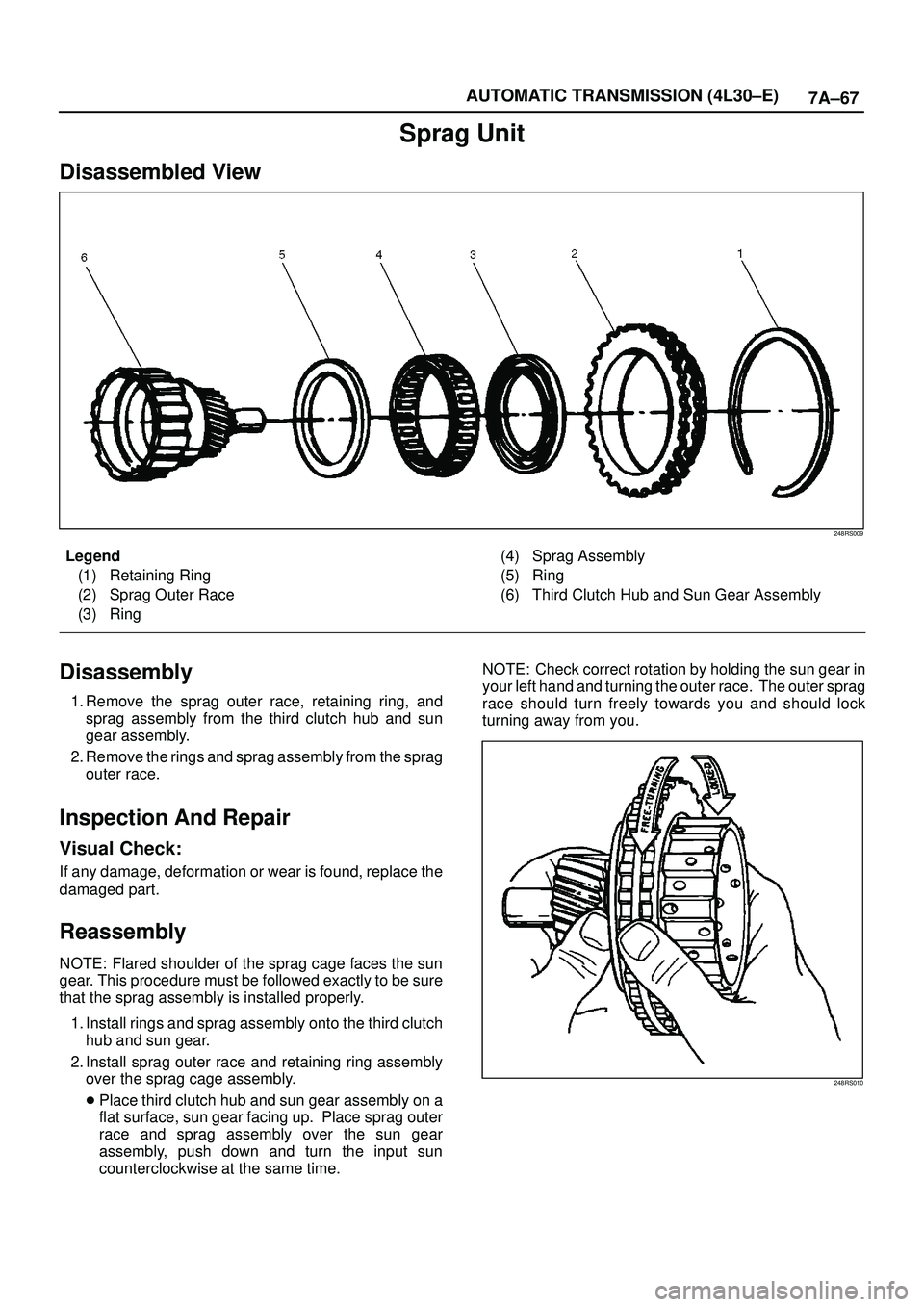
248RS009
Legend
(1) Retaining Ring
(2) Sprag Outer Race
(3) Ring(4) Sprag Assembly
(5) Ring
(6) Third Clutch Hub and Sun Gear Assembly
Disassembly
1. Remove the sprag outer race, retaining ring, and
sprag assembly from the third clutch hub and sun
gear assembly.
2. Remove the rings and sprag assembly from the sprag
outer race.
Inspection And Repair
Visual Check:
If any damage, deformation or wear is found, replace the
damaged part.
Reassembly
NOTE: Flared shoulder of the sprag cage faces the sun
gear. This procedure must be followed exactly to be sure
that the sprag assembly is installed properly.
1. Install rings and sprag assembly onto the third clutch
hub and sun gear.
2. Install sprag outer race and retaining ring assembly
over the sprag cage assembly.
�Place third clutch hub and sun gear assembly on a
flat surface, sun gear facing up. Place sprag outer
race and sprag assembly over the sun gear
assembly, push down and turn the input sun
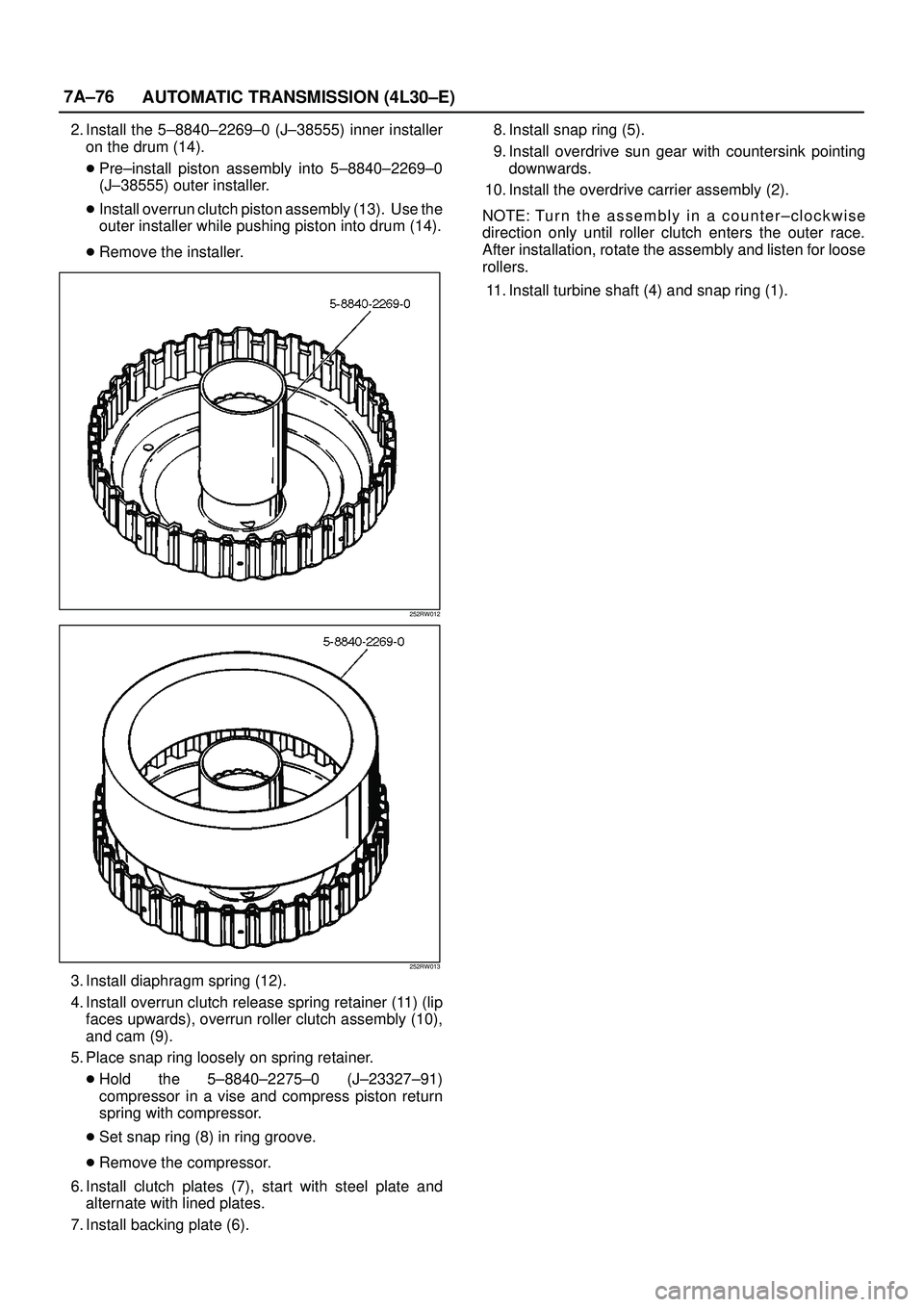
counterclockwise at the same time. NOTE: Check correct rotation by holding the sun gear in
your left hand and turning the outer race. The outer sprag
race should turn freely towards you and should lock
turning away from you.
248RS010
Page 2230 of 3573

7A±76
AUTOMATIC TRANSMISSION (4L30±E)
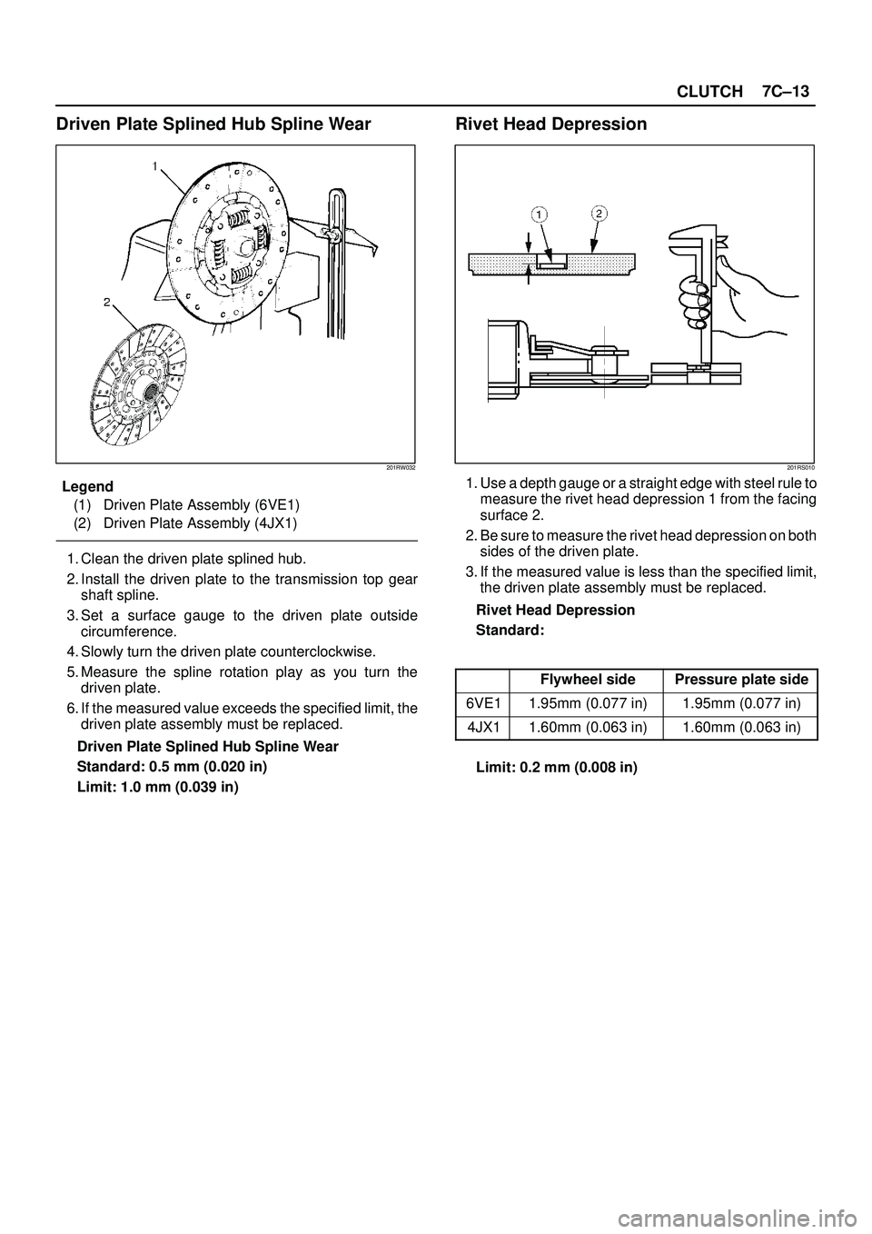
2. Install the 5±8840±2269±0 (J±38555) inner installer
on the drum (14).
�Pre±install piston assembly into 5±8840±2269±0
(J±38555) outer installer.
�Install overrun clutch piston assembly (13). Use the
outer installer while pushing piston into drum (14).
�Remove the installer.
252RW012
252RW013
3. Install diaphragm spring (12).
4. Install overrun clutch release spring retainer (11) (lip
faces upwards), overrun roller clutch assembly (10),
and cam (9).
5. Place snap ring loosely on spring retainer.
�Hold the 5±8840±2275±0 (J±23327±91)
compressor in a vise and compress piston return
spring with compressor.
�Set snap ring (8) in ring groove.
�Remove the compressor.
6. Install clutch plates (7), start with steel plate and
alternate with lined plates.
7. Install backing plate (6). 8. Install snap ring (5).
9. Install overdrive sun gear with countersink pointing
downwards.
10. Install the overdrive carrier assembly (2).
NOTE: Tu r n t h e a s sembly in a counter±clockwise
direction only until roller clutch enters the outer race.
After installation, rotate the assembly and listen for loose
rollers.
11. Install turbine shaft (4) and snap ring (1).
Page 2522 of 3573

CLUTCH7C±13
Driven Plate Splined Hub Spline Wear
201RW032
Legend
(1) Driven Plate Assembly (6VE1)
(2) Driven Plate Assembly (4JX1)
1. Clean the driven plate splined hub.
2. Install the driven plate to the transmission top gear
shaft spline.
3. Set a surface gauge to the driven plate outside
circumference.
4. Slowly turn the driven plate counterclockwise.
5. Measure the spline rotation play as you turn the
driven plate.
6. If the measured value exceeds the specified limit, the
driven plate assembly must be replaced.
Driven Plate Splined Hub Spline Wear
Standard: 0.5 mm (0.020 in)
Limit: 1.0 mm (0.039 in)
Rivet Head Depression
201RS010
1. Use a depth gauge or a straight edge with steel rule to
measure the rivet head depression 1 from the facing
surface 2.
2. Be sure to measure the rivet head depression on both
sides of the driven plate.
3. If the measured value is less than the specified limit,
the driven plate assembly must be replaced.
Rivet Head Depression
Standard:
Flywheel sidePressure plate side
6VE11.95mm (0.077 in)1.95mm (0.077 in)
4JX11.60mm (0.063 in)1.60mm (0.063 in)
Limit: 0.2 mm (0.008 in)
Page 2542 of 3573
LIGHTING SYSTEM8A–3
Headlight Bulb
Removal
1. Disconnect the battery ground cable.
2. Disconnect the connector.
3. Remove the cap(3) while turning it counter clockwise.
4. Remove the cover(2).
5. Pull the bulb(1) out from the headlight body.
CAUTION: The halogen bulb develops a very high
temperature. Do not touch the glass portion. If any
stain is on the glass surface, It will scorch and the
glass will be damaged.
801RW014
Installation
To install, follow the removal steps in the reverse order.
Page 2545 of 3573
8A–6LIGHTING SYSTEM
Fog Light Assembly
Removal
1. Disconnect the battery ground cable.
2. Remove two nuts from the bracket.
3. Disconnect the connector.
4. Remove the fog light assembly (1).
825RW104
Installation
To install, follow the removal steps in the reverse order.CAUTION: After installing the fog light, be sure to
adjust the fog light aim.
Fog Light Adjustment
Turn the adjusting screw with a screwdriver to adjust the
aim of the fog light vertically.
801RW007
Clarence Light Bulb
Removal
1. Disconnect the battery ground cable.
2. Remove the screw at the upper portion of the light
bracket and then remove the bracket from the fender.
3. Remove the front combination light assembly(1).
4. Remove the front side marker light socket(2) by
turning it counterclockwise.
5. Pull out the bulb(3) from the socket.
801RW015
Installation
To install, follow the removal steps in the reverse order.
Page 2546 of 3573
LIGHTING SYSTEM8A–7
Rear Fog Light Bulb (RHD)
Removal
1. Disconnect the battery ground cable.
2. Remove three screws and release locks at two
locations to remove the rear combination light
assembly(2).
3. Remove the socket(3) by turning it counterclockwise.
4. Turn the bulb(1) counterclockwise while pushing it to
remove it from the socket.
803RS005
Installation
To install, follow the removal steps in the reverse order.
Taillight Bulb (Body)
Removal
1. Disconnect the battery ground cable.
2. Remove three screws and release locks at two
locations to remove the rear combination light
assembly(2).
3. Remove the socket(3) by turning it counterclockwise.
4. Turn the bulb(1) counterclockwise while pushing it to
remove it from the socket.
803RS005
Installation
To install, follow the removal steps in the reverse order.
Page 2547 of 3573
8A–8LIGHTING SYSTEM
Taillight Bulb (Bumper)
Removal
1. Disconnect the battery ground cable.
2. Remove two screws to remove the rear combination
light assembly(2).
3. Remove the socket(1) by turning it counterclockwise.
4. Remove the bulb(3) by turning it counterclockwise
while pushing.
803RW004
Installation
To install, follow the removal steps in the reverse order.
License Plate Light Bulb (Body)
Removal
1. Disconnect the battery ground cable.
2. Remove two screws to remove the lens(2).
3. Pull out the bulb(1) from the socket.
803RS006
Installation
To install, follow the removal steps in the reverse order.