Page 481 of 3573

4A2A±14
DIFFERENTIAL (REAR 220mm)
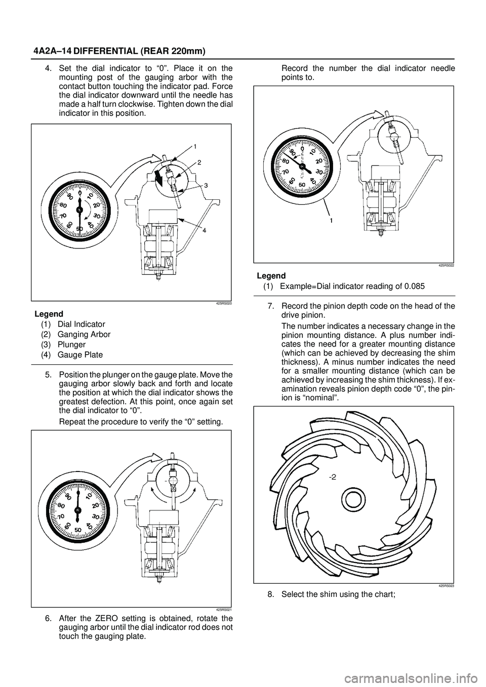
4. Set the dial indicator to ª0º. Place it on the
mounting post of the gauging arbor with the
contact button touching the indicator pad. Force
the dial indicator downward until the needle has
made a half turn clockwise. Tighten down the dial
indicator in this position.
425RS020
Legend
(1) Dial Indicator
(2) Ganging Arbor
(3) Plunger
(4) Gauge Plate
5. Position the plunger on the gauge plate. Move the
gauging arbor slowly back and forth and locate
the position at which the dial indicator shows the
greatest defection. At this point, once again set
the dial indicator to ª0º.
Repeat the procedure to verify the ª0º setting.
425RS021
6. After the ZERO setting is obtained, rotate the
gauging arbor until the dial indicator rod does not
touch the gauging plate.Record the number the dial indicator needle
points to.
425RS022
Legend
(1) Example=Dial indicator reading of 0.085
7. Record the pinion depth code on the head of the
drive pinion.
The number indicates a necessary change in the
pinion mounting distance. A plus number indi-
cates the need for a greater mounting distance
(which can be achieved by decreasing the shim
thickness). A minus number indicates the need
for a smaller mounting distance (which can be
achieved by increasing the shim thickness). If ex-
amination reveals pinion depth code ª0º, the pin-
ion is ªnominalº.
425RS023
8. Select the shim using the chart;
Page 517 of 3573

4A2B±14DIFFERENTIAL (REAR 244mm)
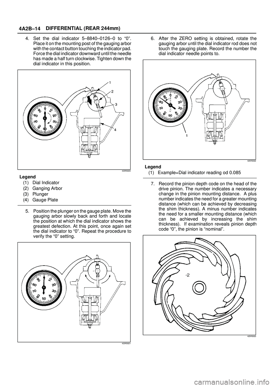
4. Set the dial indicator 5±8840±0126±0 to ª0º.
Place it on the mounting post of the gauging arbor
with the contact button touching the indicator pad.
Force the dial indicator downward until the needle
has made a half turn clockwise. Tighten down the
dial indicator in this position.
425RS020
Legend
(1) Dial Indicator
(2) Ganging Arbor
(3) Plunger
(4) Gauge Plate
5. Position the plunger on the gauge plate. Move the
gauging arbor slowly back and forth and locate
the position at which the dial indicator shows the
greatest defection. At this point, once again set
the dial indicator to ª0º. Repeat the procedure to
verify the ª0º setting.
425RS021
6. After the ZERO setting is obtained, rotate the
gauging arbor until the dial indicator rod does not
touch the gauging plate. Record the number the
dial indicator needle points to.
425RS022
Legend
(1) Example=Dial indicator reading od 0.085
7. Record the pinion depth code on the head of the
drive pinion. The number indicates a necessary
change in the pinion mounting distance. A plus
number indicates the need for a greater mounting
distance (which can be achieved by decreasing
the shim thickness). A minus number indicates
the need for a smaller mounting distance (which
can be achieved by increasing the shim
thickness). If examination reveals pinion depth
code ª0º, the pinion is ªnominalº.
425RS023
Page 681 of 3573

4C±15 DRIVE SHAFT SYSTEM
3. Remove bolt.
Before removal, shift transfer lever into ª2Hº position,
set free wheeling hub knob into ªFREEº position (1),
and run the vehicle about 50m (160 ft).
411RW010
4. Remove cover assembly.
5. Remove snap ring and shim.
6. Remove body assembly.
7. Remove lock washer and lock screw.
8. Remove hub nut by using wrench 5±8840±2117±0.
411RW005
9. Remove hub and disc assembly.
10. Remove ABS sensor ring (If equipped).
11. Remove outer bearing outer race.
12. Remove oil seal.13. Remove inner bearing outer race.
14. While pushing follower knob against cover, turn clutch
assembly clockwise and then remove clutch
assembly from knob.
411RW011
15. Remove gasket.
16. Remove snap ring.
17. Remove knob.
18. Remove compression spring.
19. Remove follower.
20. Remove retaining spring from clutch assembly by
turning it counterclockwise.
411RW012
21. Remove dedent ball and spring.
22. Remove X±ring.
23. Remove snap ring.
24. Remove inner assembly.
25. Remove snap ring.
26. Remove ring.
27. Remove spacer.
Page 683 of 3573
4C±17 DRIVE SHAFT SYSTEM
11. Install follower to clutch so that follower nails (large)
(1) will come closer to the bent portion of retaining
spring by aligning follower stopper nail with outer
teeth of clutch. Then, fit in with follower's nails (small)
(2) caught in spring.
411RW016
12. Install compression ring.
Turn the smaller diameter side toward follower and fit
spring in clutch.
13. Align follower nail (1) to handle groove (2). and then
assemble clutch with knob by pushing and turning
clutch counterclockwise to knob.
411RW017
14. Install gasket.
Make sure that there is no breakage, etc.
15. Install outer bearing outer race by driving it into the
hub, by using installer 5±8522±2118±0 and grip
5±8840±0007±0.
411RW007
16. Install inner bearing outer race by driving it into the
hub, by using installer 5±8840±2119±0 and grip
5±8840±0007±0.
411RW006
Page 741 of 3573

4D1±20
TRANSFER CASE (STANDARD TYPE)
Removal
1. Remove the speedometer sensor.
2. Remove the plate.
3. Remove the speedometer driven gear bushing and
driven gear.
NOTE: Apply a reference mark to the driven gear bushing
before removal.
4. Remove the front companion flange and the rear
companion flange, using the flange companion holder
5±8840±0133±0 (J±8614±11) to remove the end
nuts.
262RW067
NOTE: U s e a u n i v e r s a l p u l l e r t o remove the rear
companion flange.
5. Disconnect the transfer breather hose from the
control box.
6. Remove the control box assembly.
7. Remove the transfer rear cover assembly from the
transfer case assembly.
Installation
1. Apply the recommended liquid gasket (LOCTITE
17430) or its equivalent to the transfer rear cover
fitting faces.
220RS017
2. Install the transfer rear cover assembly to the transfer
case assembly.
3. Perform the following steps before fitting the transfer
rear case:
1. Shift the high±low shift rod to the 4H side.
2. Turn the select rod counterclockwise so that the
select block projection may enter into the
2WD±4WD shift block.
3. The cut±away portion of the select rod head (9)
should align with that of the rear case hole's
stopper (10).
230RW004
4. Tighten the transfer rear case bolts to the specified
torque.
Torque: 37 N´m (3.8kg´m/27 lb ft)
Page 987 of 3573

6A±31
ENGINE MECHANICAL
2. Align the alignment mark on the RH bank
camshaft drive gear pulley (2) to the alignment
mark of the cylinder head cover RH (3).
3. Align the alignment mark (white line) on the timing
belt (1) with alignment mark on the RH bank
camshaft drive gear pulley (2) (on the left side as
viewed from the front of the vehicle) and put the
timing belt on the camshaft drive gear pulley.
Secure the belt with a double clip or equivalent
clip.
014RW00004
Legend
(1) Alignment Mark on Timing Belt (White line).
(2) Alignment Mark on Camshaft Drive Gear
Pulley.
(3) Alignemnt Mark on Cylinder Head Cover RH.
4. Align the alignment mark on the LH bank
camshaft drive gear pulley (2) to the alignment
mark of the cylinder head cover LH (3).
5. Align the alignment mark (white line) on the timing
belt (1) with the alignment mark on the LH bank
camshaft drive gear pulley (2).
When aligning the timing marks, use a wrench to
turn the camshaft drive gear pulley, then set the
timing mark between timing belt and camshaft
drive gear pulley and put the timing belt on the
camshaft drive gear pulley.
Secure the belt with a double clip or equivalent
clip.
NOTE: It is recommended for easy installation that the
belt be secured with a double clip or equivalent clip after
it is installed the timing belt to each pulley.
014RW00005
Legend
(1) Alignment Mark on Timing Belt (White line).
(2) Alignment Mark on Camshaft Drive Gear
Pulley.
(3) Alignemnt Mark on Cylinder Head Cover LH.
6. Install crankshaft pulley temporarily and tighten
center bolt by hand (do not use a wrench).
Turn the crankshaft pulley clockwise to give some
belt slack between the crankshaft timing pulley
and the RH bank camshaft drive gear pulley.
2. Install pusher and tighten bolt to the specified torque.
Torque : 25 N´m (2.5 Kg´m/18 lb ft)
1. Install the pusher while pushing the tension pulley
to the belt.
2. Pull out pin from the pusher.
NOTE: When reusing the pusher, press the pusher with
approximately 100Kg to retract the rod, and insert a pin
(1.4 mm piano wire).
014RW011
Page 988 of 3573

6A±32
ENGINE MECHANICAL
Legend
(1) Up Side
(2) Down Side
(3) Direction for Installation
(4) Locking Pin
3. Remove double clips or equivalent clips, from
timing belt pulleys.
Turn the crankshaft pulley clockwise by two turns.
3. Install timing belt cover.
Remove crankshaft pulley that was installed in step
1 item 5.
Tighten bolts to the specified torque.
Torque: 19 N´m (1.9 Kg´m/14 lb ft)
020RW004
Legend
(1) Timing Belt Cover RH
(2) Timing Belt Cover LH
(3) Timing Belt Cover Lower
020RW003
Legend
(1) Timing Belt Cover
(2) Rubber Bushing
(3) Sealing Rubber
(4) Cylinder Body
4. Install crankshaft pulley using 5±8840±0133±0, hold
the crankshaft pulley and tighten center bolt to the
specified torque.
Torque : 167 N´m (17.0 Kg´m/123 lb ft)
5. Install fan pulley bracket and tighten fixing bolts to the
specified torque.
Torque : 22 N´m (2.2 Kg´m/16 lb ft)
6. Install power steering pump assembly and tighten to
the specified torque.
Torque :
M8 bolt : 22 N´m (2.2 Kg´m/16 lb ft)
M10 bolt : 46 N´m (4.7 Kg´m/34 lb ft)
7. Install cooling fan assembly and tighten bolts/nuts to
the specified torque.
Torque : 22 N´m (2.2 Kg´m/16 lb ft) for fan pulley
and fan bracket.
Torque : 10 N´m (1.0 Kg´m/88.5 lb in) for fan and
clutch assembly.
8. Move drive belt tensioner to loose side using wrench,
then install drive belt to normal position.
850RW001
Legend
(1) Crankshaft Pulley
(2) Cooling Fan Pulley
(3) Auto Tensioner
(4) Generator
(5) Air Conditioner Compressor
(6) Power Steering Oil Pump
(7) Idle Pulley
(8) Drive Belt
9. Install radiator upper fan shroud.
10. Install air cleaner assembly.
Page 1100 of 3573
6D3±9 STARTING AND CHARGING SYSTEM
22. Remove an E±ring(23) from the pinion shaft using a
flat blade screwdriver.
065RW010
23. Holding the pinion shaft, push pinion toward the
center bracket. and turn the pinion clockwise or
counterclockwise by one tooth of spline, then pull off
the pinion.
24. Remove thrust washer(24).
25. Remove center bracket
26. Remove pinion shaft.
065RW011
Inspection and Repair
Repair or replace necessary parts if extreme wear or
damage is found during inspection.
Armature
Measure the outer diameter of commutator, and replace
with a new one if it is out of the limit.
Standard: 33.0 mm (1.30 in)
Limit: 32.0 mm (1.26 in)
065RS014Check for continuity between commutator and segment.
Replace commutator if there is no continuity (i.e.,
disconnected).
065RS015