Page 1825 of 3573
6A– 92 ENGINE MECHANICAL
CYLINDER BLOCK
1
15
14
13
8
11
16
17
10
9
72
12
3
465
18
012RW023
Legend
(1) Cylinder Head
(2) Cylinder Head Gasket
(3) Flywheel
(4) Cylinder Block Rear Plate (A/T)
Flywheel Housing (M/T)
(5) Crankshaft Rear Oil Seal
(6) Retainer
(7) Timing Gear Case Cover
(8) Crankshaft Front Oil Seal(9) Timing Gear Case
(10) Gasket
(11) Balance Shaft
(12) Crank Case
(13) Piston Cooling Oil Pipe
(14) Main Bearing Cap
(15) Crankshaft
(16) Crankshaft Timing Gear
(17) Piston and Connecting Rod Assembly
(18) Cylinder Block
Page 1826 of 3573

ENGINE MECHANICAL 6A– 93
DISASSEMBLY
1. Cylinder Head Assembly
Refer to “Cylinder Head” in this manual.
2. Cylinder Head Gasket.
3. Flywheel
4. Cylinder Block Rear Plate (A/T), or Flywheel
housing (M/T).
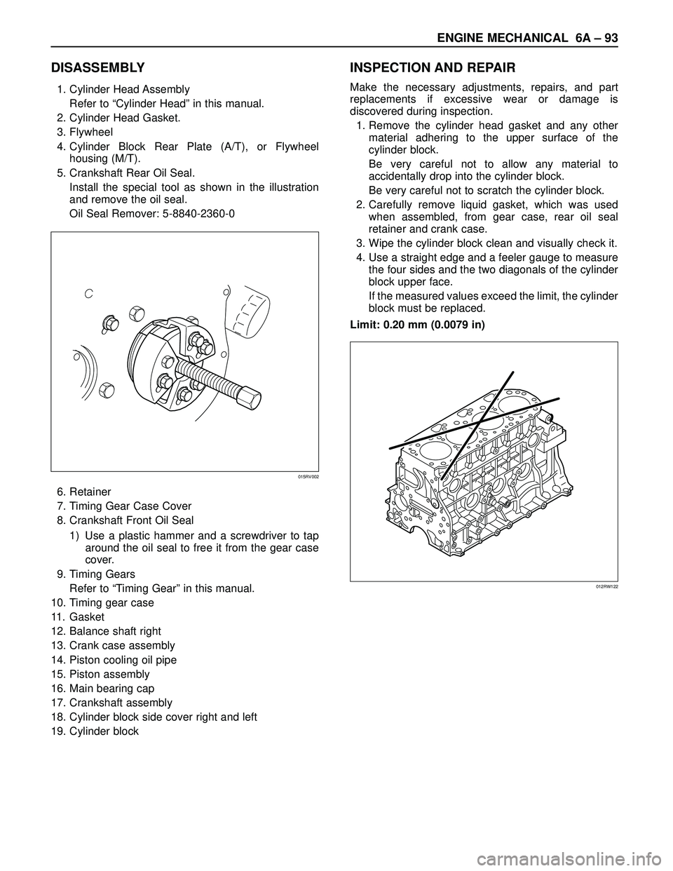
5. Crankshaft Rear Oil Seal.
Install the special tool as shown in the illustration
and remove the oil seal.
Oil Seal Remover: 5-8840-2360-0
6. Retainer
7. Timing Gear Case Cover
8. Crankshaft Front Oil Seal
1) Use a plastic hammer and a screwdriver to tap
around the oil seal to free it from the gear case
cover.
9. Timing Gears
Refer to “Timing Gear” in this manual.
10. Timing gear case
11. Gasket
12. Balance shaft right
13. Crank case assembly
14. Piston cooling oil pipe
15. Piston assembly
16. Main bearing cap
17. Crankshaft assembly
18. Cylinder block side cover right and left
19. Cylinder block
INSPECTION AND REPAIR
Make the necessary adjustments, repairs, and part
replacements if excessive wear or damage is
discovered during inspection.
1. Remove the cylinder head gasket and any other
material adhering to the upper surface of the
cylinder block.
Be very careful not to allow any material to
accidentally drop into the cylinder block.
Be very careful not to scratch the cylinder block.
2. Carefully remove liquid gasket, which was used
when assembled, from gear case, rear oil seal
retainer and crank case.
3. Wipe the cylinder block clean and visually check it.
4. Use a straight edge and a feeler gauge to measure
the four sides and the two diagonals of the cylinder
block upper face.
If the measured values exceed the limit, the cylinder
block must be replaced.
Limit: 0.20 mm (0.0079 in)
015RV002
012RW122
Page 2518 of 3573
CLUTCH7C±9
Clutch Assembly
Clutch Assembly and Associated Parts
201RW029
Legend
(1) Flywheel Assembly and Crankshaft Bearing
(2) Driven Plate Assembly (6VE1)
(3) Driven Plate Assembly (4JX1)
(4) Pressure Plate Assembly (5) Transmission Assembly
(6) Front Cover
(7) Shift Fork
(8) Release Bearing
Removal
1. Remove transmission assembly, refer to ºMANUAL
TRANSMISSIONº of Section 7B for ºRemoval AND
INSTALLATIONº procedure.
2. Mark the flywheel, clutch cover and pressure plate lug
for alignment when installing.
3. Remove pressure plate assembly (3).
4. Remove driven plate assembly (1) or (2). Use the pilot
aligner 5-85253-001-0 (J-24547) to prevent the
driven plate assembly from falling free.
201RW031
Page 2519 of 3573
7C±10CLUTCH
5. Mark the flywheel, clutch cover and pressure plate lug
for alignment when installing.
6. Remove the release bearing (3) from the
transmission case .
7. Remove the shift fork snap pin.
8. Remove the shift fork pin and shift fork (4) from the
front cover.
9. Remove the front cover bolts.
10. Remove the front cover (5) from the transmission
case.
220RW088
11. Remove flywheel assembly and crankshaft bearing.
Do not remove except for replacement.
12. Use the remover 5±8840±2000±0 (J±5822) and
sliding hammer 5±8840±0019±0 (J±23907) to
remove the crankshaft bearing
015RW053
Inspection and Repair
Make necessary correction or parts replacement if wear,
damage, or any other abnormal condition are found
through inspection.
Pressure Plate Assembly
201RS002
1. Visually check the pressure plate friction surface for
excessive wear and heat cracks.
2. If excessive wear or deep heat cracks are present,
the pressure plate must be replaced.
Pressure Plate Warpage
201RS003
Page 2524 of 3573

CLUTCH7C±15
Installation
To install, follow the removal steps in the reverse order,
noting the following points:
1. Install flywheel assembly and crankshaft bearing.
Use the installer 5-8840-0125-0 (J-26516-A) and
driver handle 5-8840-0007-0 (J-8092) to install the
crankshaft bearing then clean and lubricate with
grease.
015RW054
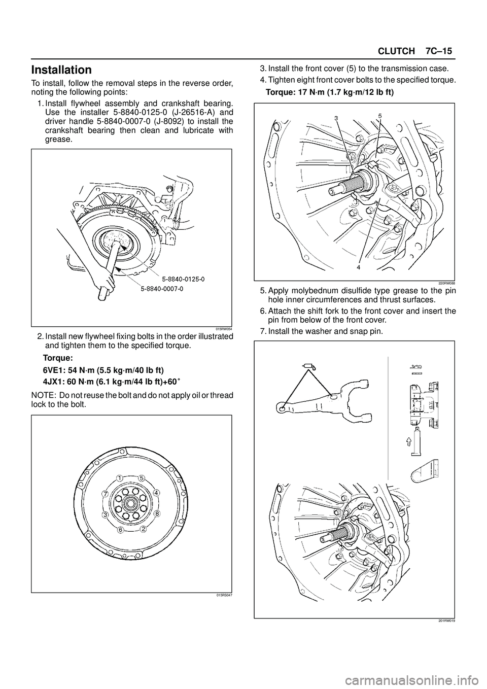
2. Install new flywheel fixing bolts in the order illustrated
and tighten them to the specified torque.
Torque:
6VE1: 54 N´m (5.5 kg´m/40 lb ft)
4JX1: 60 N´m (6.1 kg´m/44 lb ft)+60�
NOTE: Do not reuse the bolt and do not apply oil or thread
lock to the bolt.
015RS047
3. Install the front cover (5) to the transmission case.
4. Tighten eight front cover bolts to the specified torque.
Torque: 17 N´m (1.7 kg´m/12 lb ft)
220RW088
5. Apply molybednum disulfide type grease to the pin
hole inner circumferences and thrust surfaces.
6. Attach the shift fork to the front cover and insert the
pin from below of the front cover.
7. Install the washer and snap pin.
201RW019