Page 25 of 3573

GENERAL INFORMATION 0AÐ11
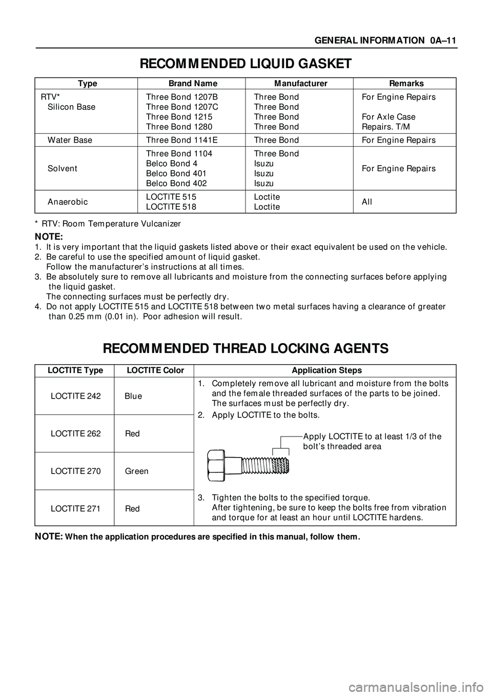
RECOMMENDED LIQUID GASKET
* RTV: Room Temperature Vulcanizer
NOTE:
1. It is very important that the liquid gaskets listed above or their exact equivalent be used on the vehicle.
2. Be careful to use the specified amount of liquid gasket.
Follow the manufacturerÕs instructions at all times.
3. Be absolutely sure to remove all lubricants and moisture from the connecting surfaces before applying
the liquid gasket.
The connecting surfaces must be perfectly dry.
4. Do not apply LOCTITE 515 and LOCTITE 518 between two metal surfaces having a clearance of greater
than 0.25 mm (0.01 in). Poor adhesion will result.
RECOMMENDED THREAD LOCKING AGENTS
NOTE:When the application procedures are specified in this manual, follow them.
Type Brand Name Manufacturer Remarks
RTV* Three Bond 1207B Three Bond For Engine Repairs
Silicon Base Three Bond 1207C Three Bond
Three Bond 1215 Three Bond For Axle Case
Three Bond 1280 Three Bond Repairs. T/M
Water Base Three Bond 1141E Three Bond For Engine Repairs
Three Bond 1104 Three Bond
Belco Bond 4 Isuzu
Solvent
Belco Bond 401 Isuzu For Engine Repairs
Belco Bond 402 Isuzu
LOCTITE 515 Loctite
Anaerobic
LOCTITE 518 Loctite All
LOCTITE Type LOCTITE Color Application Steps
LOCTITE 242 Blue
LOCTITE 262 Red
LOCTITE 270 Green
LOCTITE 271 Red
1. Completely remove all lubricant and moisture from the bolts
and the female threaded surfaces of the parts to be joined.
The surfaces must be perfectly dry.
2. Apply LOCTITE to the bolts.
Apply LOCTITE to at least 1/3 of the
boltÕs threaded area
3. Tighten the bolts to the specified torque.
After tightening, be sure to keep the bolts free from vibration
and torque for at least an hour until LOCTITE hardens.
Page 207 of 3573
AIR CONDITIONING 1BÐ81
C01RY00001
2
1
123
4
10
96 5
87
11
13
B
B
A
C
B
C
A
ABB
A
A
B
A
A
B
B
A
C
A
A
C
CC
B
AB
AABB
Vent DoorMode PositionDisplay of Intake StatusSet Temperature
ONFULL
COLDFULL
HOT 20~30�Æ
�™
BBAA�™
Blue
VENT BI-LEVEL FOOT DEFRed
OFF
Foot Door
DEF Door
Intake Door
Air Mix Door
Sub Air Mix DoorWhite
C
C
B
DEF/FOOT
C
A
Legend
(1) Interior Air Intake
(2) Fresh Air Intake
(3) Pollen Filter
(4) Evaporator Core
(5) Air Mix Door
(6) DEF Door(7) Vent Door
(8) Foot Door
(9) Sub Air Mix Door
(10) Heater Unit
(11) Heater Core
(12) Evaporator Unit
(13) Blower Unit
Air Control Functions
Page 224 of 3573

1BÐ98 AIR CONDITIONING
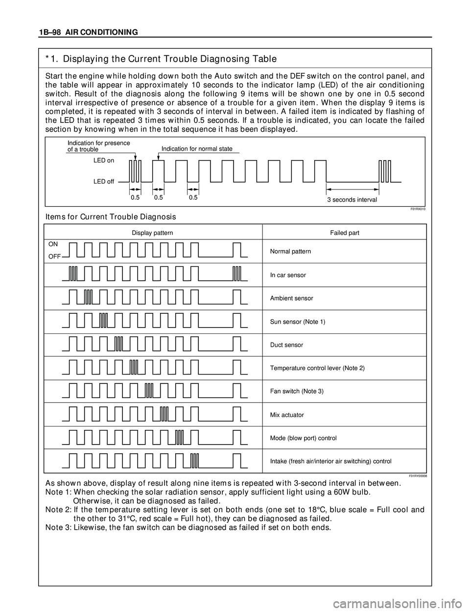
*1. Displaying the Current Trouble Diagnosing Table
Start the engine while holding down both the Auto switch and the DEF switch on the control panel, and
the table will appear in approximately 10 seconds to the indicator lamp (LED) of the air conditioning
switch. Result of the diagnosis along the following 9 items will be shown one by one in 0.5 second
interval irrespective of presence or absence of a trouble for a given item. When the display 9 items is
completed, it is repeated with 3 seconds of interval in between. A failed item is indicated by flashing of
the LED that is repeated 3 times within 0.5 seconds. If a trouble is indicated, you can locate the failed
section by knowing when in the total sequence it has been displayed.
Items for Current Trouble Diagnosis
As shown above, display of result along nine items is repeated with 3-second interval in between.
Note 1: When checking the solar radiation sensor, apply sufficient light using a 60W bulb.
Otherwise, it can be diagnosed as failed.
Note 2: If the temperature setting lever is set on both ends (one set to 18¡C, blue scale = Full cool and
the other to 31¡C, red scale = Full hot), they can be diagnosed as failed.
Note 3: Likewise, the fan switch can be diagnosed as failed if set on both ends.
LED on
LED off Indication for presence
of a troubleIndication for normal state
0.5 0.5 0.5
3 seconds interval
ON
OFF
Display pattern Failed part
Normal pattern
In car sensor
Ambient sensor
Sun sensor (Note 1)
Duct sensor
Temperature control lever (Note 2)
Fan switch (Note 3)
Mix actuator
Mode (blow port) control
Intake (fresh air/interior air switching) control
F01RX010
F01RY00008
Page 456 of 3573
4A1±19 DIFFERENTIAL (FRONT)
17. Tighten the cap bolt to the specified torque.
Torque: 98 N´m (10kg´m/72 lb ft)
425RS036
1. Measure the amount of run±out of the ring gear at
its rear face.
Standard: 0.02 mm ( 0.001 in)
Limit: 0.05 mm ( 0.002 in)
425RS037
Gear Tooth Contact Pattern Check and Adjustment
1. Apply a thin coat of prussian blue or equivalent
to the faces of the 7±8 teeth of the ring gear.
Check the impression of contact on the ring
gear teeth and make necessary adjustment as
described in illustration if the contact is
abnormal.
425RS038
Legend
(1) Heel
(2) Toe
(3) Concave Side(Coast)
(4) Convex Side(Drive)
Page 486 of 3573
DIFFERENTIAL (REAR 220mm)
4A2A±19
17. Tighten the cap bolt to the specified torque.
Torque: 108 N´m (11.0kg´m/80 lb ft)
425RS036
1. Measure the amount of run±out of the ring gear at
its rear face.
Standard: 0.02 mm ( 0.001 in)
Limit: 0.05 mm ( 0.002 in)
425RS037
Gear Tooth Contact Pattern Check and Adjustment
1. Apply a thin coat of prussian blue or equivalent
to the faces of the 7±8 teeth of the ring gear.
Check the impression of contact on the ring
gear teeth and make necessary adjustment as
described in illustration if the contact is
abnormal.
425RS038
Legend
(1) Heel
(2) Toe
(3) Concave Side(Coast)
(4) Convex Side(Drive)
Page 522 of 3573
DIFFERENTIAL (REAR 244mm)
4A2B±19
16. Tighten the bolt to the specified torque.
Torque:108N´m (11.0kg´m/80 lb ft)
425RS036
Gear Tooth Contact Pattern Check and Adjustment
1. Apply a thin coat of Prussian blue or equivalent to the
faces of the 7±8 teeth of the ring gear. Check the
impression of contact on the ring gear teeth and make
necessary adjustment as described in illustration if
the contact is abnormal.
425RS038
Legend
(1) Heel
(2) Toe
(3) Concave Side(Coast)
(4) Convex Side(Drive)
425RS039
Page 538 of 3573
4B1±5 DRIVE LINE CONTROL SYSTEM (SHIFT ON THE FLY)
4. If vacuum is not applicable as much as ±400mmHg,
and if there is resistance on the intake side, replace
with a new check valve.
VSV Assembly
Inspect the vehicle side harness as follows:
412RS071
Legend
(1) Grey
(2) Blue
1. Remove connector.
2. Shift transfer lever to 2H and start the engine.
NOTE: Do not move the vehicle while inspection.
3. Make sure that there is continuity in the vehicle side of
harness. If there is no continuity, check transfer shift
switch and wiring.
Inspect both VSVs as follows:
F04RS004
1. With battery not connected (Usual).
A±C:There is continuity
B:Closed
2. With battery connected
A ± B:There is continuity
C:Closed
3. If 1) and 2) fail, replace with a new VSV.
Axle Position Switch
412RS048
1. With ball (1) being free
A ± B:There is continuity
2. With ball forced into the switch
A ± B:No continuity
3. If 1) and 2) fail, replace with a new switch.
Page 567 of 3573

4B1±34
DRIVE LINE CONTROL SYSTEM (SHIFT ON THE FLY)
4. If vacuum is not applicable as much as ±400mmHg,
and if there is resistance on the intake side, replace
with a new check valve.
VSV Assembly
Inspect the vehicle side harness as follows:
412RS071
Legend
(1) Grey
(2) Blue
1. Remove connector.
2. Shift transfer lever to 2H and start the engine.
NOTE: Do not move the vehicle while inspection.
3. Make sure that there is continuity in the vehicle side of
harness. If there is no continuity, check transfer shift
switch and wiring.
Inspect both VSVs as follows:
F04RS004
1. With battery not connected (Usual).
A±C:There is continuity
B:Closed
2. With battery connected
A ± B:There is continuity
C:Closed
3. If 1) and 2) fail, replace with a new VSV.
Axle Position Switch
412RS048
1. With ball (1) being free
A ± B:There is continuity
2. With ball forced into the switch
A ± B:No continuity
3. If 1) and 2) fail, replace with a new switch.
Motor Actuator Assembly
Inspect the function of the motor actuator assembly as
follows: