Page 1445 of 3573
6E±328
ENGINE DRIVEABILITY AND EMISSIONS
3. Connect the vacuum hoses to the EVAP canister
purge solenoid.
014RW137
4. Connect the electrical connector to the EVAP canister
purge solenoid.
014RW138
Fuel Tank Vent Valve
Removal and Installation Procedure
Refer to Fuel Pump
Linear Exhaust Gas
Recirculation (EGR) Valve
Removal Procedure
1. Disconnect the negative battery cable.2. Disconnect the electrical connector at the EGR valve.
014RW139
3. Remove the bolt and the nut from the upper intake
manifold.
014RW098
4. Remove the EGR valve from the upper intake
manifold.
5. Remove the gasket from the upper intake manifold.
Installation Procedure
1. Install the gasket on the upper intake manifold.
2. Install the EGR valve on the upper intake manifold.
3. Secure the EGR valve and the gasket with the bolt
and the nut.
Page 1446 of 3573
6E±329 ENGINE DRIVEABILITY AND EMISSIONS
NOTE: It is possible to install the EGR valve rotated 180�
from the correct position. Make sure that the base of the
valve is placed so that it aligns with the mounting flange.
014RW098
4. Connect the electrical connector at the EGR valve.
014RW139
5. Connect the negative battery cable.
Positive Crankcase Ventilation
(PCV) Valve
Removal Procedure
1. Remove the vacuum hose at the PCV valve.
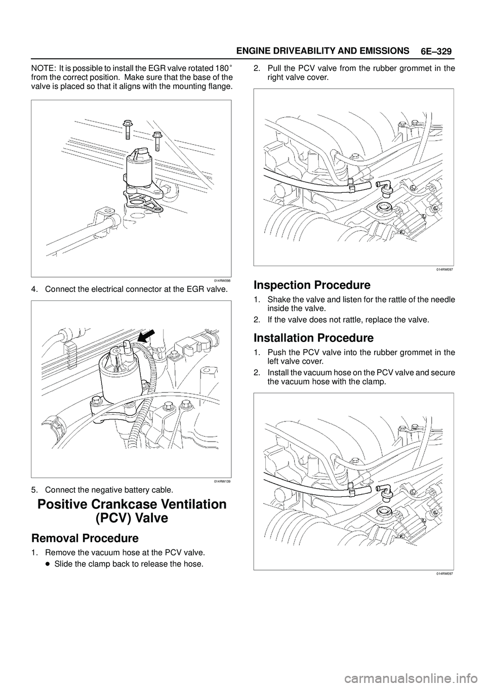
�Slide the clamp back to release the hose.2. Pull the PCV valve from the rubber grommet in the
right valve cover.
014RW097
Inspection Procedure
1. Shake the valve and listen for the rattle of the needle
inside the valve.
2. If the valve does not rattle, replace the valve.
Installation Procedure
1. Push the PCV valve into the rubber grommet in the
left valve cover.
2. Install the vacuum hose on the PCV valve and secure
the vacuum hose with the clamp.
014RW097
Page 1447 of 3573

6E±330
ENGINE DRIVEABILITY AND EMISSIONS
Wiring and Connectors
Wiring Harness Service
The control module harness electrically connects the
control module to the various solenoids, switches and
sensors in the vehicle engine compartment and
passenger compartment.
Replace wire harnesses with the proper part number
replacement.
Because of the low amperage and voltage levels utilized
in powertrain control systems, it is essential that all wiring
in environmentally exposed areas be repaired with crimp
and seal splice sleeves.
The following wire harness repair information is intended
as a general guideline only. Refer to
Chassis Electrical for
all wire harness repair procedures.
Connectors and Terminals
Use care when probing a connector and when replacing
terminals. It is possible to short between opposite
terminals. Damage to components could result. Always
use jumper wires between connectors for circuit
checking. NEVER probe through Weather-Pack seals.
Use an appropriate connector test adapter kit which
contains an assortment of flexible connectors used to
probe terminals during diagnosis. Use an appropriate
fuse remover and test tool for removing a fuse and to
adapt the fuse holder to a meter for diagnosis.
Open circuits are often difficult to locate by sight because
oxidation or terminal misalignment are hidden by the
connectors. Merely wiggling a connector on a sensor, or
in the wiring harness, may temporarily correct the open
circuit. Intermittent problems may also be caused by
oxidized or loose connections.
Be certain of the type of connector/terminal before
making any connector or terminal repair. Weather-Pack
and Com-Pack III terminals look similar, but are serviced
differently.
PCM Connectors and Terminals
Removal Procedure
1. Remove the connector terminal retainer.
2. Push the wire connected to the affected terminal
through the connector face so that the terminal is
exposed.
3. Service the terminal as necessary.
Installation Procedure
1. Bend the tab on the connector to allow the terminal to
be pulled into position within the connector.
2. Pull carefully on the wire to install the connector
terminal retainer.
Wire Harness Repair: Twisted
Shielded Cable
Removal Procedure
1. Remove the outer jacket.
2. Unwrap the aluminum/mylar tape. Do not remove the
mylar.
047
3. Untwist the conductors.
4. Strip the insulation as necessary.
048
Page 1448 of 3573
6E±331 ENGINE DRIVEABILITY AND EMISSIONS
Installation Procedure
1. Splice the wires using splice clips and rosin core
solder.
2. Wrap each splice to insulate.
3. Wrap the splice with mylar and with the drain
(uninsulated) wire.
049
4. Tape over the whole bundle to secure.
050
Twisted Leads
Removal Procedure
1. Locate the damaged wire.
2. Remove the insulation as required.
051
Installation Procedure
1. Use splice clips and rosin core solder in order to splice
the two wires together.
052
Page 1449 of 3573
6E±332
ENGINE DRIVEABILITY AND EMISSIONS
2. Cover the splice with tape in order to insulate it from
the other wires.
053
3. Twist the wires as they were before starting this
procedure.
054
4. Tape the wires with electrical tape. Hold in place.
055
Weather-Pack Connector
Tools Required
J 28742-A Weather-Pack II Terminal Remover
Removal Procedure
A Weather-Pack connector can be identified by a rubber
seal at the rear of the connector. This engine room
connector protects against moisture and dirt, which could
from oxidation and deposits on the terminals. This
protection is important, because of the low voltage and
the low amperage found in the electronic systems.
1. Open the secondary lock hinge on the connector.
070
Page 1450 of 3573

6E±333 ENGINE DRIVEABILITY AND EMISSIONS
2. Use tool J 28742-A or the equivalent to remove the
pin and the sleeve terminals. Push on J 28742-A to
release.
NOTE: Do the use an ordinary pick or the terminal may
be bent or deformed. Unlike standard blade terminals,
these terminals cannot be straightened after they have
been improperly bent.
071
3. Cut the wire immediately behind the cable seal.
072
Installation Procedure
Make certain the connectors are properly seated and all
of the sealing rings are in place when you reconnect the
leads. The secondary lock hinge provides a backup
locking feature for the connector. The secondary lock
hinge is used for added reliability. This flap should retain
the terminals even if the small terminal lock tangs are not
positioned properly.
Do not replace the Weather-Pack connections with
standard connections. Read the instructions provided
with the Weather-Pack connector and terminal packages.
1. Replace the terminal.2. Slip the new seal onto the wire.
3. Strip 5 mm (0.2º) of insulation from the wire.
4. Crimp the terminal over the wire and the seal.
073
5. Push the terminal and the connector to engage the
locking tangs.
070
6. Close the secondary locking hinge.
Com-Pack III
General Information
The Com-Pack III terminal looks similar to some
Weather-Pack terminals. This terminal is not sealed and
is used where resistance to the environment is not
required. Use the standard method when repairing a
terminal. Do not use the Weather-Pack terminal tool J
28742-A or equivalent. These will damage the terminals.
Metri-Pack
Tools Required
J 35689 Terminal Remover
Page 1470 of 3573
6E±353 ENGINE DRIVEABILITY AND EMISSIONS
ILLUSTRATIONTOOL NO.
TOOL NAME
5-8840-0285-0
(J 39200)
High Impedance
Multimeter (Digital
Voltmeter ± DVM)
(1) PCMCIA Card
(2) RS232 Loop Back
Connector
(3) SAE 16/19 Adapter
(4) DLC Cable
(5) TECH±2
5-8840-0607-0
(J 34142-B)
Unpowered Test Light
5-8840-0385-0
(J 35616-A/BT-8637)
Connector Test
Adapter Kit
5-8840-0383-0
(J 26792/BT-7220-1)
Spark Tester
5-8840-0279-0
(J 23738-A)
Vacuum Pump with
Gauge common tool
ILLUSTRATIONTOOL NO.
TOOL NAME
BT-8515
Exhaust Back Pressure
Tester or common tool
5-8840-2640-0
(J 39194-B)
Heated Oxygen Sensor
Wrench
5-8840-0632-0
(J 35689-A)
Terminal Remover
5-8840-0388-0
(J 28742-A)
Weather Pack II
Terminal Remover
5-8840-2635-0
(J 39021-90)
Injector Switch Box
5-8840-2636-0
(J 39021-65)
Injector Test Light
Page 1475 of 3573
 Front Exhaust Pipe RH Fixing Nuts
(2) Front Exhaust Pipe RH Fixing Bolts and Nuts
(3) O
2 Sensor Term")
6F±4ENGINE EXHAUST
Front Exhaust Pipe
Front Exhaust Pipe and Associated Parts
150RW063
Legend
(1) Front Exhaust Pipe RH Fixing Nuts
(2) Front Exhaust Pipe RH Fixing Bolts and Nuts
(3) O
2 Sensor Terminal Connector (for IGM)
(4) Front Exhaust Pipe LH Fixing Nuts(5) Front Exhaust Pipe LH Fixing Bolts and Nuts
(6) Front Exhaust Pipe LH
(7) Front Exhaust Pipe RH
(8) Three way Exhaust Pipe Fixing Bolts and Nuts
Removal
1. Disconnect battery ground cable.
2. Raise the vehicle and support with suitable safety
stands.
3. Disconnect O
2 sensor harness connector (3).
4. Remove front exhaust pipe fixing nuts and three way
Exhaust Pipe Fixing Bolts and Nuts (2)(5)(8).
5. Remove front exhaust pipe fixing three stud nuts from
exhaust manifold (1)(4).
6. Remove front exhaust pipe (6)(7).
Installation
1. Install front exhaust pipe (6)(7) and tighten three stud
nuts (1)(4) and nuts (2)(5)(8) to the specified torque.
Torque
Stud Nuts : 67 N´m (6.8 Kg´m/49 lb ft)
Nuts : 43 N´m (4.3 Kg´m/32 lb ft)
2. Reconnect O
2 sensor harness connector (3).


High Impedance
Multimeter (Digital
Voltmeter ± DVM)
(1) PCMCIA Card
(2) RS232 Loop Back
Connector
(3")