Page 1428 of 3573
6E±311 ENGINE DRIVEABILITY AND EMISSIONS
3. Disconnect the fuel line from the fuel filter on the
engine side.
4. Disconnect the fuel line from the fuel filter on the fuel
tank side.
041RW006
5. Remove the bolt on the fuel filter holder.
041RW007
6. Remove the fuel filter.
041RW008
Inspection Procedure
1. Replace the fuel filter when the following occur:
�Fuel leaks from the fuel filter body.
�The fuel filter body is damaged.
�The fuel filter is clogged with dirt or sediment.
2. If the drain hole is clogged, clean the drain.
041RW009
Page 1430 of 3573
6E±313 ENGINE DRIVEABILITY AND EMISSIONS
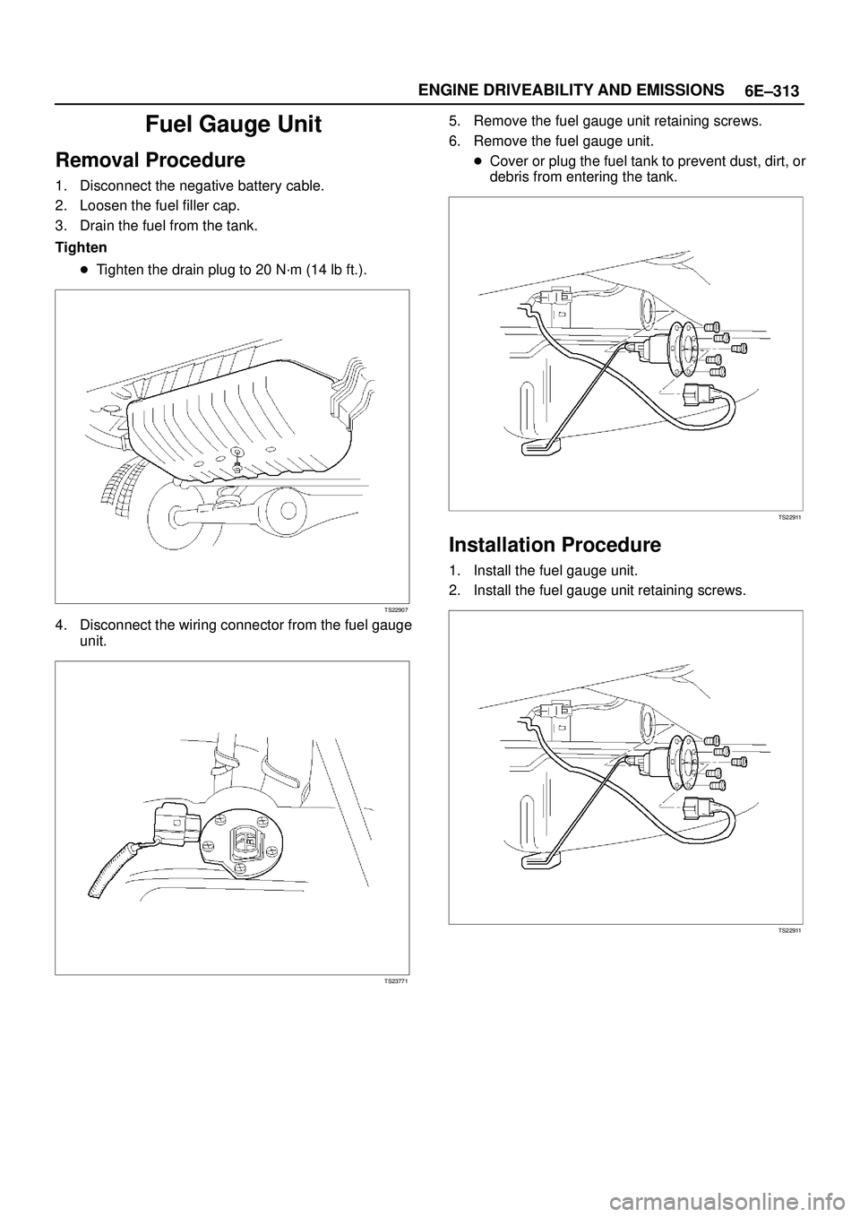
Fuel Gauge Unit
Removal Procedure
1. Disconnect the negative battery cable.
2. Loosen the fuel filler cap.
3. Drain the fuel from the tank.
Tighten
�Tighten the drain plug to 20 N´m (14 lb ft.).
TS22907
4. Disconnect the wiring connector from the fuel gauge
unit.
TS23771
5. Remove the fuel gauge unit retaining screws.
6. Remove the fuel gauge unit.
�Cover or plug the fuel tank to prevent dust, dirt, or
debris from entering the tank.
TS22911
Installation Procedure
1. Install the fuel gauge unit.
2. Install the fuel gauge unit retaining screws.
TS22911
Page 1431 of 3573

6E±314
ENGINE DRIVEABILITY AND EMISSIONS
3. Connect the wiring connector to the fuel gauge unit.
TS23771
4. Fill the fuel tank with fuel.
�Tighten the fuel filler cap.
�Check for leaks at the fuel gauge unit gasket.
5. Connect the negative battery cable.
Fuel Injectors
Removal Procedure
NOTE: If the fuel injectors are leaking, the engine oil may
be contaminated with fuel. Check the oil for signs of
contamination and change the oil and the filter if
necessary.
NOTE: Use care in removing the fuel injectors in order to
prevent damage to the fuel injector electrical connector
pins or the fuel injector nozzles. The fuel injector is an
electrical component and should not be immersed in any
type of cleaner as this may damage the fuel injector.
IMPORTANT:Fuel injectors are serviced as a complete
assembly only.
1. Disconnect the negative battery cable.
2. Remove the upper intake manifold. Refer to
Common Chamber in Engine Mechanical..
3. Remove the fuel rail. Refer to
Fuel Rail.
014RW164
4. Remove the injector retainer clip.
055RW009
5. Remove the fuel injector assembly.
6. Remove the O-ring from the fuel injector.
7. Remove the O-ring backup from the fuel injector .
Inspection Procedure
1. Inspect the O-rings for cracks or leaks.
2. Replace worn or damaged O-rings.
3. Lubricate the new O-rings with engine oil before
installation.
Page 1432 of 3573

6E±315 ENGINE DRIVEABILITY AND EMISSIONS
Installation Procedure
1. Install the O-ring backup on the fuel injector.
2. Install the new O-ring on the fuel injector.
3. Install the fuel injector on the fuel rail.
055RW009
4. Use new fuel injector retainer clips to retain the fuel
injector to the fuel rail.
5. Coat the end of the fuel injector with engine oil.
6. Install the fuel rail. Refer to
Fuel Rail.
014RW164
7. Install the upper intake manifold. Refer to Common
Chamber in Engine Mechanical.
8. Install the engine cover.
9. Connect the negative battery cable.
Fuel Pressure Regulator
Removal Procedure
CAUTION: To reduce the risk of fire and personal
injury, it is necessary to relieve the fuel system
pressure before servicing the fuel system
components.
CAUTION: After relieving the system pressure, a
small amount of fuel may be released when servicing
fuel lines or connections. Reduce the chance of
personal injury by covering the fuel line fittings with
a shop towel before disconnecting the fittings. The
towels will absorb any fuel that may leak out. When
the disconnect is completed, place the towel in an
approved container.
NOTE: Compressed air must never be used to test or
clean a fuel pressure regulator, as damage to the fuel
pressure regulator may result.
NOTE: To prevent damage to the fuel pressure regulator,
do not immerse the pressure regulator in solvent.
1. Depressurize the fuel system. Refer to
Fuel Pressure
Relief Procedure
.
2. Disconnect the negative battery cable.
3. Remove the fuel pump relay. Refer to
Fuel Pump
Relay
.
4. Remove the pressure regulator hose from the fuel
pressure regulator.
014RW110
Page 1433 of 3573
6E±316
ENGINE DRIVEABILITY AND EMISSIONS
5. Remove the two bolts from the protector that secures
the common chamber.
014RW109
6. Remove the fuel pressure regulator attaching screw.
F06RW043
7. Remove the fuel pressure regulator from the fuel rail.
Disassembly Procedure
1. Remove the O-ring from the fuel pressure regulator.
2. Loosen the swivel nut.
3. Remove the fuel return line from the fuel pressure
regulator.
4. Remove the O-ring from the fuel return line.
�The O-ring may be left inside the fuel pressure
regulator instead of on the fuel return line.
F06RW043
Assembly Procedure
1. Install a new O-ring on the fuel return line.
2. Install the fuel return line on the fuel pressure
regulator.
NOTE: Do not over-tighten the swivel nut on the fuel
pressure regulator. The fuel pressure regulator can be
damaged and fuel may leak if the swivel nut is
over-tightened.
3. Tighten the swivel nut.
4. Install a new O-ring on the fuel pressure regulator.
Page 1434 of 3573

6E±317 ENGINE DRIVEABILITY AND EMISSIONS
Installation Procedure
1. Install the fuel pressure regulator attaching screw.
Tighten
�Tighten the fuel pressure regulator attaching screw
to 3 N´m (26 lb in.).
F06RW043
2. Install the fuel pressure regulator on the fuel rail.
3. Install the two bolts to the protector that secures the
common chamber.
014RW109
4. Install the pressure regulator hose to the fuel
pressure regulator.
014RW110
5. Install the fuel pump relay. Refer to Fuel Pump Relay.
6. Connect the negative battery cable.
7. Crank the engine until it starts. Cranking the engine
may take longer than usual due to trapped air in the
fuel lines.
Fuel Metering System
Fuel Pressure Relief Procedure
CAUTION: To reduce the risk of fire and personal
injury, it is necessary to relieve the fuel system
pressure before servicing the fuel system
components.
CAUTION: After relieving the system pressure, a
small amount of fuel may be released when servicing
fuel lines or connections. Reduce the chance of
personal injury by covering the fuel line fittings with
a shop towel before you disconnect the fittings. The
towels will absorb any fuel that may leak out. When
the disconnect is completed, place the towel in an
approved container.
1. Remove the fuel cap.
Page 1435 of 3573

6E±318
ENGINE DRIVEABILITY AND EMISSIONS
2. Remove the fuel pump relay from the underhood
relay box. Refer to
Fuel Pump Relay.
TS23976R
3. Start the engine and allow it to stall.
4. Crank the engine for 30 seconds.
5. Disconnect the negative battery cable.
Fuel Pump Assembly
Removal Procedure
1. Disconnect the negative battery cable.
2. Drain all the fuel from the tank.
3. Install and tighten the drain plug.
Tighten
�Tighten the drain plug to 20 N´m (14 lb ft.).
4. Remove the fuel tank. Refer to
Fuel Tank.
5. Remove the retaining screws from the fuel tank.
6. Remove the fuel pump assembly from the fuel tank.
�Cover the fuel pump opening in order to prevent
dust, dirt, or debris from entering the fuel tank.
TS23795
Inspection Procedure
1. Inspect the fuel pump gasket for tears, cracks,
stretching, or rotting. If any of these conditions are
found, replace the fuel pump gasket.
2. Inspect the in-tank fuel filter for tears or evidence of
dirt, debris, or water in the fuel. If any of these
conditions are found, replace the in-tank fuel filter.
Installation Procedure
1. Install the fuel pump assembly.
2. Install the fuel pump assembly retaining screws.
3. Install the fuel tank assembly. Refer to
Fuel Tank.
4. Fill the tank with fuel.
5. Tighten the fuel filler cap.
6. Connect the negative battery cable.
TS23795
Page 1436 of 3573

6E±319 ENGINE DRIVEABILITY AND EMISSIONS
Fuel Pump Relay
Removal Procedure
1. Remove the fuse and relay box cover from under the
hood.
2. Consult the diagram on the cover to determine which
is the correct relay.
3. Insert a small screwdriver into the catch slot on the
forward side of the fuel pump relay.
�The screwdriver blade will release the catch inside.
T321092
4. Pull the relay straight up and out of the fuse and relay
box.
TS23976R
Installation Procedure
1. Insert the relay into the correct place in the fuse and
relay box with the catch slot facing forward.
2. Press down until the catch engages.
�An audible ªclickº will be heard.
T321092
3. Install the fuse and relay box cover.
Fuel Rail Assembly
Removal Procedure
NOTE:
�Do not attempt to remove the fuel inlet fitting on the
fuel rail. It is staked in place. Removing the fuel inlet
fitting will result in damage to the fuel rail or the
internal O-ring seal.
�Use care when removing the fuel rail assembly in
order to prevent damage to the injector electrical
connector terminals and the injector spray tips.
�Fittings should be capped and holes plugged during
servicing to prevent dirt and other contaminants from
entering open lines and passages.