Page 1487 of 3573

013RW004
2. Install oil pan
1. Remove residual sealant, lub")
6G±8
ENGINE LUBRICATION
3. Install crankcase, tighten crankcase fixing bolts
to the specified torque.
Torque : 10 N´m (1.0 Kg´m/89 lb in)
013RW004
2. Install oil pan
1. Remove residual sealant, lubricant and moisture
from mounting surface, then dry thoroughly.
2. Properly apply a 4.5 mm (07 in) wide bead of
sealant (TB-1207C or equivalent) to mounting
surface of oil pan.
Sealant beat must be continuous.
�The crankcase must be installed within 5
minutes after sealant application befor the
sealant hardens.
013RW003
3. Install oil pan, tighten oil pan fixing bolts to the
specified torque.
Torque : 25 N´m (2.5 Kg´m/18 lb ft)3. Install axle housing assembly and tighten fixing bolts
to the specified torque.
Axle case bolts
Torque : 82 N´m (8.4 Kg´m/60 lb ft)
Mounting bolts
Torque : 152 N´m (15.5 Kg´m/112 lb ft)
013RW005
4. Install relay lever assembly and tighten fixing bolts.
Torque: 44 N´m (4.5 Kg´m/32 lb ft)
5. Engage teeth of pitman arm and steering unit, and
tighten nut to the specified torque.
Torque : 216 N´m (22.0 Kg´m/159 lb ft)
013RW006
Legend
(1) Pitman Arm
(2) Relay Lever
Page 1489 of 3573

6G±10
ENGINE LUBRICATION
Oil Pump
Removal
1. Disconnect battery ground cable.
2. Drain engine oil.
3. Remove crankcase assembly.
� Refer to removal procedure for Oil Pan and
Crankcase in this manual.
4. Remove crankshaft pulley.
�Refer to removal procedure for Crankshaft Pulley in
this manual.
5. Remove timing belt.
�Refer to removal procedure for Timing Belt in this
manual.
6. Remove timing pulley from crankshaft.
7. Remove four fixing bolts from oil filter assembly.
8. Remove oil strainer fixing bolts, remove oil strainer
assembly with O-ring.
9. Remove three bolts from oil pipe and O-ring.
10. Remove eight oil pump fixing bolts, then oil pump
assembly.
11. Remove sealant from mounting surface of oil pump
assembly, cylinder block and take care not to damage
mounting surfaces of oil pump and cylinder block.
Installation
1. Install oil pump assembly
�Apply sealant (TB-1207B or equivalent) to the oil
pump mounting surfaces as shown in the
illustration.
�The oil pump assembly must be installed within 5
minutes after sealant application before the sealant
hardens.
NOTE: Do not apply sealant to the oil ports.
051RW002
�Use 5±8840±2287±0 installer when installing new
oil seal.
�Apply engine oil to oil seal lip.
�Install oil pump assembly to the cylinder block.
NOTE: Do not damage oil seal during installation of oil
pump assembly.
015RS001
�Tighten fixing bolts to the specified torque.
Torque : 25 N´m (2.5 Kg´m/18 lb ft)
051RW001
2. Install oil pipe with O-ring, tighten fixing bolt to the
specified torque.
Torque : 10 N´m (1.0 Kg´m/89 lb in)
3. Install oil strainer with O-ring, tighten fixing bolt to the
specified torque.
Torque : 25 N´m (2.5 Kg´m/18 lb ft)
Page 1491 of 3573
6G±12
ENGINE LUBRICATION
Oil Pump Oil Seal
Removal
1. Disconnect battery ground cable.
2. Drain engine oil.
3. Remove crankshaft pulley.
�Refer to removal procedure for Crankshaft Pulley in
this manual.
4. Remove timing belt.
�Refer to removal procedure for Timing Belt in this
manual.
5. Remove timing pulley from crankshaft.
6. Remove oil pump oil seal using a sealer puller.
NOTE: Take care not to damage sealing surfaces of oil
pump and crankshaft when removing oil seal.
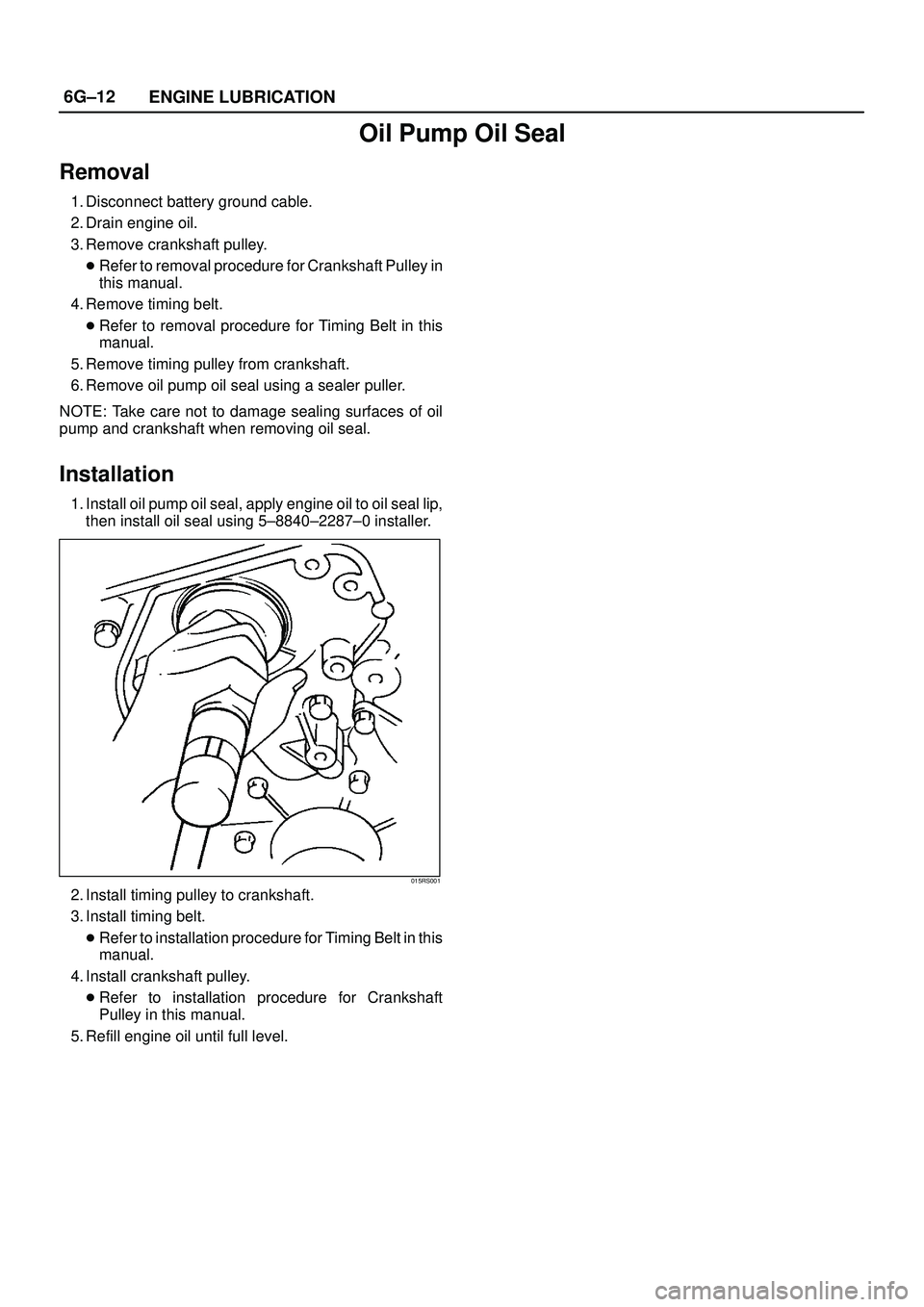
Installation
1. Install oil pump oil seal, apply engine oil to oil seal lip,
then install oil seal using 5±8840±2287±0 installer.
015RS001
2. Install timing pulley to crankshaft.
3. Install timing belt.
�Refer to installation procedure for Timing Belt in this
manual.
4. Install crankshaft pulley.
�Refer to installation procedure for Crankshaft
Pulley in this manual.
5. Refill engine oil until full level.
Page 1492 of 3573
6G±13 ENGINE LUBRICATION
Oil Filter
Removal
1. Disconnect battery ground cable.
2. Drain engine oil.
3. Remove oil filter using 5-8840-0203-0 filter wrench.
Installation
1. Clean filter fitting surface and apply small amount of
engine oil to sealing surface.
2. Install oil filter cartridge by hand until it comes in
contact with sealing surface then rotate additional 2/3
turn to tighten using 5-8840-0203-0 filter wrench.
050RW001
Legend
(1) Oil Pump
(2) Oil Filter
(3) Oil Gallery
(4) From Filter
(5) To Filter
3. Fill engine oil until full level on dipstick.
4. Reconnect battery ground cable.
Page 1496 of 3573
 on the cable bracket
mounted on the common chamber.
2. Remove cable clip(3).
3. Disconnect acce")
6H±2
ENGINE SPEED CONTROL SYSTEM
Accelerator Pedal Control Cable
Removal
1. Loosen the adjusting nut(5) on the cable bracket
mounted on the common chamber.
2. Remove cable clip(3).
3. Disconnect accelerator pedal (AP) control cable(6).
(on throttle valve side)
4. Disconnect AP control cable(1). (on AP pedal(7) side)
5. Remove molding cap(2).
6. Remove AP control cable(4).
101RW001
Inspection
Check the following items, and replace the control cable if
any abnormality is found:
�The control cable should move smoothly.
�The control cable should not be bent or kinked.
�The control cable should be free of damage and
corrosion.
Installation
1. Install AP control cable(4).
2. Install molding cap(2).
3. Connect AP control cable(1). (on AP side)
4. Connect AP control cable(6). (on throttle valve side)
5. Install cable clip(3).
6. Install adjusting nut(5).
101RW001
Adjustment
1. Loosen adjusting nut and lock nut.
2. Pull outer cable while closing fully the throttle valve.
3. Tighten adjusting nut and lock nut temporarily.
4. Loosen adjusting nut by three turns and tighten lock
nut.
Then, manually operating the throttle valve, make
sure that the valve lever returns up to the stopper
screw.
If it does not reach the stopper screw, repeat from
step 1.
035RW004
Legend
(1) Clearance
(2) Lock Nut
(3) Adjusting Nut
Page 1528 of 3573

4. Dry the element in a well vent")
00 Ð 28 SERVICE INFORMATION
3. Remove the element from the solution and rinse it well
with running water.
Water pressure must not exceed 274 Kpa (2.8 kg/cm
2/40
Psi)
4. Dry the element in a well ventilated area.
An electric fan will hasten drying.
NOTE:
Do not use compressed air or an open flame to dry the
element quickly. Damage to the element will result.
It will usually take two or three days for the element to dry
completely. Therefore, it is a good idea to have a spare on
hand to use in the interim.
LUBRICATING SYSTEM
Main Oil Filter (Cartridge Type Paper Element)
Replacement Procedure
1. Loosen the drain plug to drain the engine oil.
2. Wait a few minutes and then retighten the drain plug.
3. Loosen the used oil filter by turning it counterclockwise
with the filter wrench.
4. Clean the oil cooler fitting face.
This will allow the new oil filter to seat properly.
5. Apply a light coat of engine oil to the O-ring.
6. Turn in the new oil filter until the filter O-ring is fitted
against the sealing face.
7. Use the filter wrench to turn in the filter an additional 1
and 1/4 turns.
Filter Wrench: 5-8840-0200-0
8. Check the engine oil level and replenish to the specified
level if required.
0.7 (0.62/0.74)
lit(Imp qt / US qt) Replenishment Engine Oil
9. Start the engine and check for oil leakage from the main
oil filter.
Page 1529 of 3573

SERVICE INFORMATION 00 Ð 29
FUEL SYSTEM
Fuel Filter
Replacement Procedure
1. Loosen the used fuel filter by turning it counterclock-
wise with the filter wrench.
Filter Wrench: 5-8840-0253-0 (J-22700)
2. Remove the level sensor from the filter by turning it
counterclockwise with a wrench.
3. Install the level sensor to the new fuel filter with a
wrench.
5. Apply a light coat of engine oil to the O-ring.
6. Turn in the fuel filter until the sealing face comes in
contact with the O-ring.
7. Turn in the fuel filter an additional 2/3 of a turn with a
filter wrench.
Filter Wrench: 5-8840-0253-0 (J-22700)
8. Loosen the bleeder plug on the injection pump overflow
valve.
9. Operate the priming pump until fuel begins to flow from
the fuel filter.
10. Retighten the bleeder plug.
11. Operate the priming pump several times and check for
fuel leakage.
NOTE:
The use of an ISUZU genuine fuel filter is strongly recom-
mended.
13 (1.3/9)
N·m (Kg·m/lb·ft) Level Sensor Torque
4. Clean the filter cover fitting faces.
This will allow the new fuel filter to seat properly.
Page 1531 of 3573

SERVICE INFORMATION 00 Ð 31
Remove the radiator filler cap only when absolutely neces-
sary.
Always check the coolant level when the engine is cold.
Always refer to the chart at the left to determine the correct
cooling water to antifreeze solution mixing ratio.
Cooling System Inspection
Install a radiator filler cap tester to the radiator. Apply
testing pressure to the cooling system to check for leakage.
The testing pressure must not exceed the specified pres-
sure.
Radiator Cap Inspection
The radiator filler cap is designed to maintain coolant pres-
sure in the cooling system at 1.05 kg/cm
2 (15 psi/103 kPa).
Check the radiator filler cap with a radiator filler cap tester.
The radiator filler cap must be replaced if it fails to hold the
specified pressure during the test procedure.
Radiator Filler Cap Pressure
Thermostat Operating Test
1. Completely submerge the thermostat in water.
2. Heat the water.
Stir the water constantly to avoid direct heat being
applied to the thermostat.
3. Check the thermostat initial opening temperature.
82 (180)
°C(°F) Thermostat Initial
Opening Temperature
4. Check the thermostat full opening temperature.
1.0 – 3.9 (0.01 – 0.04/0.14 – 0.57)
Negative Valve (Reference)Kpa (Kg/cm2 / Psi)
90 (194)
°C(°F) Thermostat Full
Opening Temperature
10 (0.39)
mm(in) Valve Lift at Fully Open Position
196 (2/28.45)
Testing Pressure Kpa (Kg/cm2 / Psi)
93.3 – 122.7 (0.95 – 1.25/13.5 –17.8)
Pressure Valve
Kpa (Kg/cm2 / Psi)