Page 1533 of 3573
SERVICE INFORMATION 00 Ð 33
ENGINE CONTROL
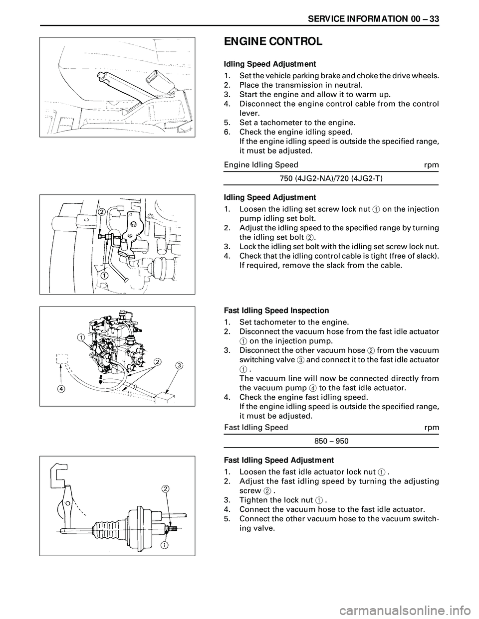
Idling Speed Adjustment
1. Set the vehicle parking brake and choke the drive wheels.
2. Place the transmission in neutral.
3. Start the engine and allow it to warm up.
4. Disconnect the engine control cable from the control
lever.
5. Set a tachometer to the engine.
6. Check the engine idling speed.
If the engine idling speed is outside the specified range,
it must be adjusted.
Fast Idling Speed Adjustment
1. Loosen the fast idle actuator lock nut 1 .
2. Adjust the fast idling speed by turning the adjusting
screw 2 .
3. Tighten the lock nut 1 .
4. Connect the vacuum hose to the fast idle actuator.
5. Connect the other vacuum hose to the vacuum switch-
ing valve.750 (4JG2-NA)/720 (4JG2-T)
rpm Engine Idling Speed
Idling Speed Adjustment
1. Loosen the idling set screw lock nut 1 on the injection
pump idling set bolt.
2. Adjust the idling speed to the specified range by turning
the idling set bolt 2.
3. Lock the idling set bolt with the idling set screw lock nut.
4. Check that the idling control cable is tight (free of slack).
If required, remove the slack from the cable.
Fast Idling Speed Inspection
1. Set tachometer to the engine.
2. Disconnect the vacuum hose from the fast idle actuator
1 on the injection pump.
3. Disconnect the other vacuum hose 2 from the vacuum
switching valve 3 and connect it to the fast idle actuator
1 .
The vacuum line will now be connected directly from
the vacuum pump 4 to the fast idle actuator.
4. Check the engine fast idling speed.
If the engine idling speed is outside the specified range,
it must be adjusted.
850 – 950
rpm Fast Idling Speed
Page 1534 of 3573
00 Ð 34 SERVICE INFORMATION
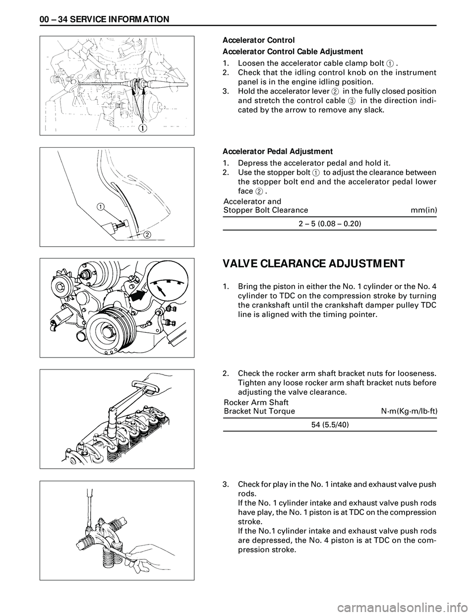
Accelerator Control
Accelerator Control Cable Adjustment
1. Loosen the accelerator cable clamp bolt 1 .
2. Check that the idling control knob on the instrument
panel is in the engine idling position.
3. Hold the accelerator lever 2 in the fully closed position
and stretch the control cable 3 in the direction indi-
cated by the arrow to remove any slack.
Accelerator Pedal Adjustment
1. Depress the accelerator pedal and hold it.
2. Use the stopper bolt 1 to adjust the clearance between
the stopper bolt end and the accelerator pedal lower
face 2 .
VALVE CLEARANCE ADJUSTMENT
1. Bring the piston in either the No. 1 cylinder or the No. 4
cylinder to TDC on the compression stroke by turning
the crankshaft until the crankshaft damper pulley TDC
line is aligned with the timing pointer.
2. Check the rocker arm shaft bracket nuts for looseness.
Tighten any loose rocker arm shaft bracket nuts before
adjusting the valve clearance.
3. Check for play in the No. 1 intake and exhaust valve push
rods.
If the No. 1 cylinder intake and exhaust valve push rods
have play, the No. 1 piston is at TDC on the compression
stroke.
If the No.1 cylinder intake and exhaust valve push rods
are depressed, the No. 4 piston is at TDC on the com-
pression stroke.
54 (5.5/40)
N·m(Kg·m/lb·ft) Rocker Arm Shaft
Bracket Nut Torque2 – 5 (0.08 – 0.20)
mm(in) Accelerator and
Stopper Bolt Clearance
Page 1535 of 3573
SERVICE INFORMATION 00 Ð 35
Adjust the No. 1 or the No. 4 cylinder valve clearances while
their respective cylinders are at TDC on the compression
stroke.
0.4 (0.016)
mm(in) Valve Clearance (At Cold)
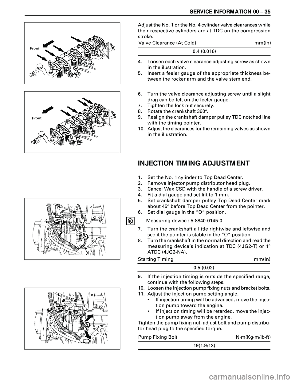
4. Loosen each valve clearance adjusting screw as shown
in the ilustration.
5. Insert a feeler gauge of the appropriate thickness be-
tween the rocker arm and the valve stem end.
6. Turn the valve clearance adjusting screw until a slight
drag can be felt on the feeler gauge.
7. Tighten the lock nut securely.
8. Rotate the crankshaft 360°.
9. Realign the crankshaft damper pulley TDC notched line
with the timing pointer.
10. Adjust the clearances for the remaining valves as shown
in the illustration.
INJECTION TIMING ADJUSTMENT
1. Set the No. 1 cylinder to Top Dead Center.
2. Remove injector pump distributor head plug.
3. Cancel Wax CSD with the handle of a screw driver.
4. Fit a dial gauge and set lift to 1 mm.
5. Set crankshaft damper pulley Top Dead Center mark
about 45° before Top Dead Center from the pointer.
6. Set dial gauge in the ÒOÓ position.
Measuring device : 5-8840-0145-0
7. Turn the crankshaft a little rightwise and leftwise and
see it the pointer is stable in the ÒOÓ position.
8. Turn the crankshaft in the normal direction and read the
measuring deviceÕs indication at TDC (4JG2-T) or 1°
ATDC (4JG2-NA).
9. If the injection timing is outside the specified range,
continue with the following steps.
10. Loosen the injection pump fixing nuts and bracket bolts.
11. Adjust the injection pump setting angle.
¥ If injection timing will be advanced, move the injec-
tion pump toward the engine.
¥ If injection timing will be retarded, move the injec-
tion pump away from the engine.
Tighten the pump fixing nut, adjust bolt and pump distribu-
tor head plug to the specified torque.
19(1.9/13)
N·m(Kg·m/lb·ft) Pump Fixing Bolt
0.5 (0.02)
mm(in) Starting Timing
Page 1536 of 3573
00 Ð 36 SERVICE INFORMATION
CAUTION
¥ When installing the distributor head plug, be sure to use
new copper washer.
COMPRESSION PRESSURE MEASURE-
MENT
1. Start the engine and allow it to idle until the coolant
temperature reaches 70 Ð 80°C (158 Ð 176°F).
2. Remove the following parts.
* Glow plugs
* Fuel cut solenoid connector
* QOS (Quick-On Start System) fusible link wire at the
connector.
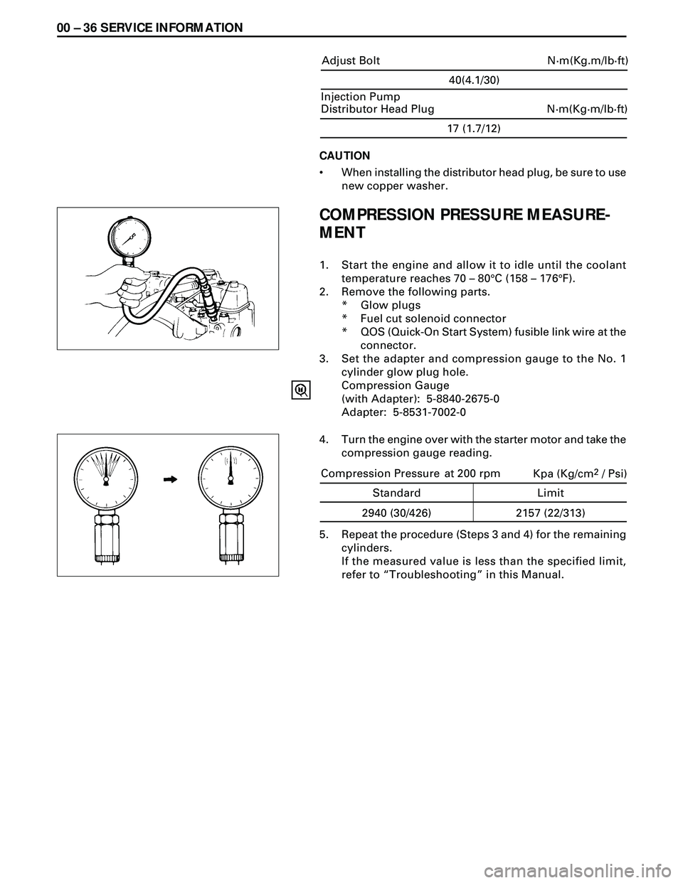
3. Set the adapter and compression gauge to the No. 1
cylinder glow plug hole.
Compression Gauge
(with Adapter): 5-8840-2675-0
Adapter: 5-8531-7002-0
5. Repeat the procedure (Steps 3 and 4) for the remaining
cylinders.
If the measured value is less than the specified limit,
refer to ÒTroubleshootingÓ in this Manual.
17 (1.7/12)
N·m(Kg·m/lb·ft) Injection Pump
Distributor Head Plug
4. Turn the engine over with the starter motor and take the
compression gauge reading.
40(4.1/30)
N·m(Kg.m/lb·ft) Adjust Bolt
Kpa (Kg/cm2 / Psi)
Standard Limit
2940 (30/426) 2157 (22/313) Compression Pressure at 200 rpm
Page 1537 of 3573
SERVICE INFORMATION 00 Ð 37
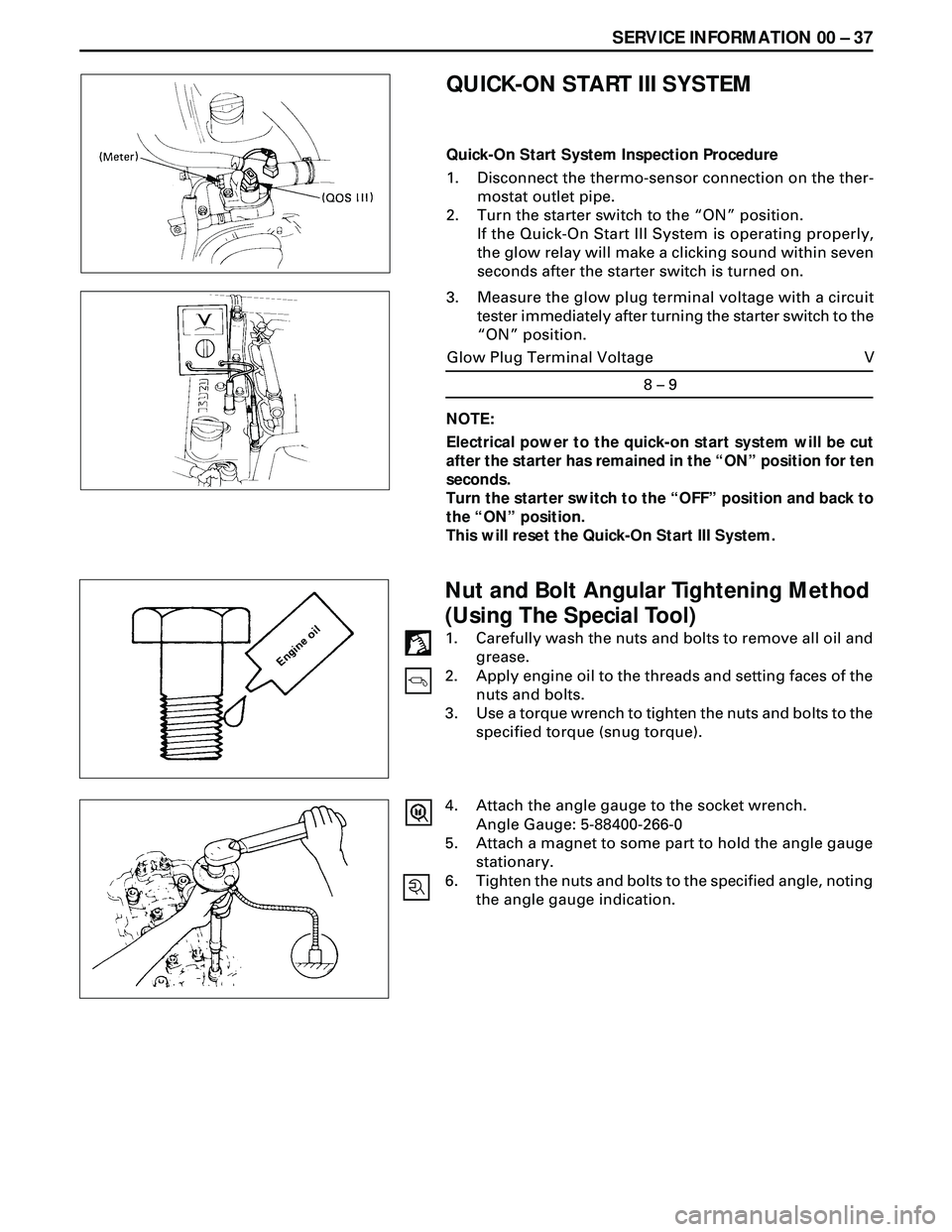
3. Measure the glow plug terminal voltage with a circuit
tester immediately after turning the starter switch to the
ÒONÓ position.
8 – 9
V Glow Plug Terminal Voltage
QUICK-ON START III SYSTEM
Quick-On Start System Inspection Procedure
1. Disconnect the thermo-sensor connection on the ther-
mostat outlet pipe.
2. Turn the starter switch to the ÒONÓ position.
If the Quick-On Start III System is operating properly,
the glow relay will make a clicking sound within seven
seconds after the starter switch is turned on.
NOTE:
Electrical power to the quick-on start system will be cut
after the starter has remained in the ÒONÓ position for ten
seconds.
Turn the starter switch to the ÒOFFÓ position and back to
the ÒONÓ position.
This will reset the Quick-On Start III System.
Nut and Bolt Angular Tightening Method
(Using The Special Tool)
1. Carefully wash the nuts and bolts to remove all oil and
grease.
2. Apply engine oil to the threads and setting faces of the
nuts and bolts.
3. Use a torque wrench to tighten the nuts and bolts to the
specified torque (snug torque).
4. Attach the angle gauge to the socket wrench.
Angle Gauge: 5-88400-266-0
5. Attach a magnet to some part to hold the angle gauge
stationary.
6. Tighten the nuts and bolts to the specified angle, noting
the angle gauge indication.
Page 1548 of 3573
00 Ð 48 SERVICE INFORMATION
SPECIAL TOOLS (CONT.1)
5-8840-0145-0
5-8522-0024-0
5-8840-0266-0
5-8840-9016-0
5-8840-2038-0
5-8840-2061-0
ILLUSTRATION
TOOL NAME TOOL NO.
Measuring Device
Crankshaft Timing Gear Installer
Angle Gauge
Injection Nozzle Tester
Bearing Replacer
Crankshaft Front Oil Seal Installer
5-8840-2032-0
5-8840-0259-0
5-8840-0253-0 (J-22700)Engine Hanger
Nozzle Holder Wrench
Fuel Filter Wrench
5-8840-2360-0 Crankshaft Rear Oil Seal Remover
5-8840-2359-0 Crankshaft Rear Oil Seal Installer
Page 1552 of 3573
6A Ð 2 ENGINE MECHANICAL
CYLINDER HEAD
NOTE:
·During disassembly, be sure that the valve train
components are kept together and identified so that
they can be re-installed in their original locations.
·Before removing the cylinder head from the engine
and before disassembling the valve mechanism, make
a compression test and note the results.
DISASSEMBLY
1. Thermostat Housing Assembly
2. Injection Nozzle Holder
3. Glow Plug and Glow Plug Connector
4. Rocker Arm Shaft and Rocker Arm
5. Push Rod
6. Cylinder Head
·Refer to Section 6A2 ÒCylinder HeadÓ
CLEAN
·Cylinder head bolts
·Cylinder head
Carefully remove all varnish, soot and carbon to the
bare metal. Do not use a motorized wire brush on any
gasket sealing surface.
Page 1554 of 3573
6A Ð 4 ENGINE MECHANICAL
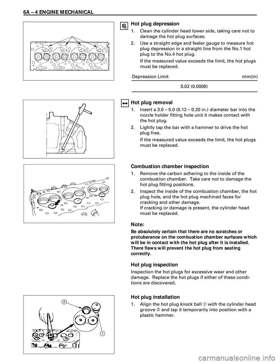
Hot plug depression
1. Clean the cylinder head lower side, taking care not to
damage the hot plug surfaces.
2. Use a straight edge and feeler gauge to measure hot
plug depression in a straight line from the No.1 hot
plug to the No.4 hot plug.
If the measured value exceeds the limit, the hot plugs
must be replaced.
Hot plug removal
1. Insert a 3.0 Ð 5.0 (0.12 Ð 0.20 in.) diameter bar into the
nozzle holder fitting hole unit it makes contact with
the hot plug.
2. Lightly tap the bar with a hammer to drive the hot
plug free.
If the measured value exceeds the limit, the hot plugs
must be replaced.
mm(in)
0.02 (0.0008) Depression Limit
Combustion chamber inspection
1. Remove the carbon adhering to the inside of the
combustion chamber. Take care not to damage the
hot plug fitting positions.
2. Inspect the inside of the combustion chamber, the hot
plug hole, and the hot plug machined faces for
cracking and other damage.
If cracking or damage is present, the cylinder head
must be replaced.
Note:
Be absolutely certain that there are no scratches or
protuberance on the combustion chamber surfaces which
will be in contact with the hot plug after it is installed.
There flaws will prevent the hot plug from seating
correctly.
Hot plug inspection
Inspection the hot plugs for excessive wear and other
damage. Replace the hot plugs if either of these condi-
tions are discovered.
Hot plug installation
1. Align the hot plug knock ball À with the cylinder head
groove Á and tap it temporarily into position with a
plastic hammer.