Page 1585 of 3573
ENGINE MECHANICAL 6A Ð 35
6. Piston Ring
Remove the piston rings with a piston ring expander.
Arrange the removed piston rings in the cylinder
number order.
7. Piston Pin Snap Ring
·Use a pair of pliers to remove the piston pin snap
rings
8. Piston Pin
NOTE:
Keep the parts removed from each cylinder separate. All
parts must be reinstalled in their original positions.
9. Piston
10. Connecting Rod
INSPECTION AND REPAIR
PISTON AND PISTON RING
Pistons
Carefully clean away all the carbon adhering to the piston
head and the piston ring grooves.
NOTE:
Never use a wire brush to clean the pistons. Damage will
result.
Visually check each piston for cracking, scoring, and other
signs of excessive wear.
If any of the above conditions are present, the piston
must be replaced.
Piston Diameter
1. Measure the piston outside diameter with micrometer
at the piston grading position.
71.00 (2.7974)
mm(in) Piston Grading Position
Page 1589 of 3573

ENGINE MECHANICAL 6A Ð 39
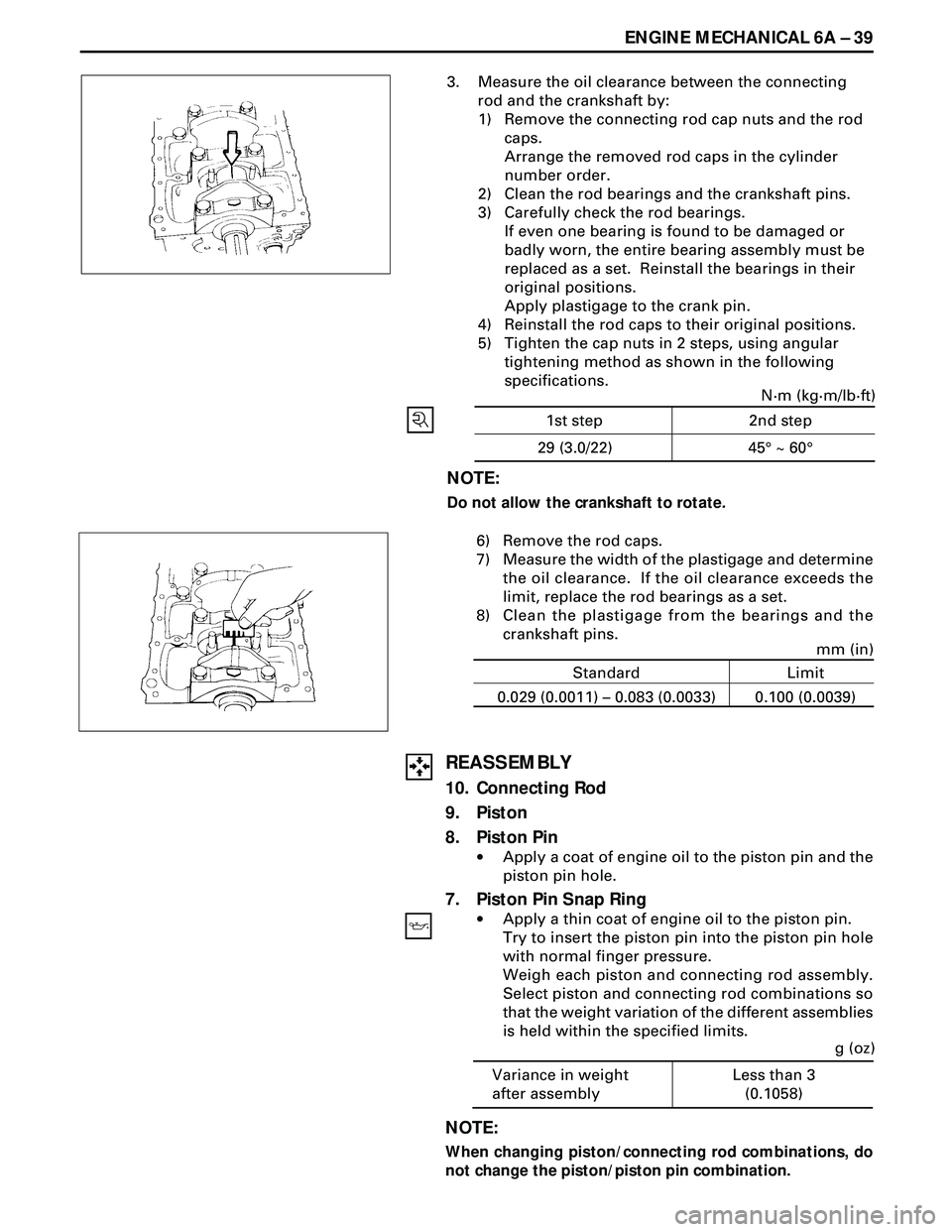
3. Measure the oil clearance between the connecting
rod and the crankshaft by:
1) Remove the connecting rod cap nuts and the rod
caps.
Arrange the removed rod caps in the cylinder
number order.
2) Clean the rod bearings and the crankshaft pins.
3) Carefully check the rod bearings.
If even one bearing is found to be damaged or
badly worn, the entire bearing assembly must be
replaced as a set. Reinstall the bearings in their
original positions.
Apply plastigage to the crank pin.
4) Reinstall the rod caps to their original positions.
5) Tighten the cap nuts in 2 steps, using angular
tightening method as shown in the following
specifications.
NOTE:
Do not allow the crankshaft to rotate.
N·m (kg·m/lb·ft)
45¡ ~ 60¡ 1st step 2nd step
29 (3.0/22)
6) Remove the rod caps.
7) Measure the width of the plastigage and determine
the oil clearance. If the oil clearance exceeds the
limit, replace the rod bearings as a set.
8) Clean the plastigage from the bearings and the
crankshaft pins.
REASSEMBLY
10. Connecting Rod
9. Piston
8. Piston Pin
·Apply a coat of engine oil to the piston pin and the
piston pin hole.
7. Piston Pin Snap Ring
·Apply a thin coat of engine oil to the piston pin.
Try to insert the piston pin into the piston pin hole
with normal finger pressure.
Weigh each piston and connecting rod assembly.
Select piston and connecting rod combinations so
that the weight variation of the different assemblies
is held within the specified limits.
Variance in weight
after assemblyLess than 3
(0.1058)g (oz)
Standard Limit
0.029 (0.0011) – 0.083 (0.0033) 0.100 (0.0039)
mm (in)
NOTE:
When changing piston/connecting rod combinations, do
not change the piston/piston pin combination.
Page 1592 of 3573
6A Ð 42 ENGINE MECHANICAL
CYLINDER BLOCK
DISASSEMBLY
1. Cylinder Head Assembly
·Refer to ÒCylinder headÓ in Section 6A2.
2. Cylinder Head Gasket
3. Flywheel
4. Cylinder Block Rear Plate
5. Crankshaft Rear Oil Seal
·With the oil seal pushed in deep, install the special
tool as shown in the illustration and remove the oil
seal.
Oil Seal Remover : 5-8840-2362-0
6. Crankcase Assembly
·Refer to ÒCrankcaseÓ in Section 6A2
7. Oil Pump Assembly
Page 1593 of 3573
ENGINE MECHANICAL 6A Ð 43
8. Camshaft Timing Gear
9. Camshaft Thrust Plate
10. Camshaft
11. Crankshaft Front Oil Seal
·With the oil seal pushed in deep, install the special
tool as shown in the illustration and remove the oil
seal.
Oil Seal Remover : 5-8840-2362-0
12. Timing Gear Case
13. Tappet
14. Piston Assembly
15. Main Bearing Cap Assembly
16. Crankshaft
17. Piston Cooling Oil Pipe
18. Cylinder Block
Page 1594 of 3573

6A Ð 44 ENGINE MECHANICAL
INSPECTION REPAIR
Make the necessary adjustments, repairs, and part replacements if excessive wear or damage is discovered
during inspection.
1. Remove the gasket and any other material adhering to
the upper surface of the cylinder block.
Be very careful not to allow any material to accidentally
drop into the cylinder block.
Be very careful not to scratch the cylinder block.
2. Carefully remove the oil pump, Rear Oil Seal retainer,
and oil pan installation surface seal.
3. Wipe the cylinder block clean.
Cylinder Liner Projection Inspection
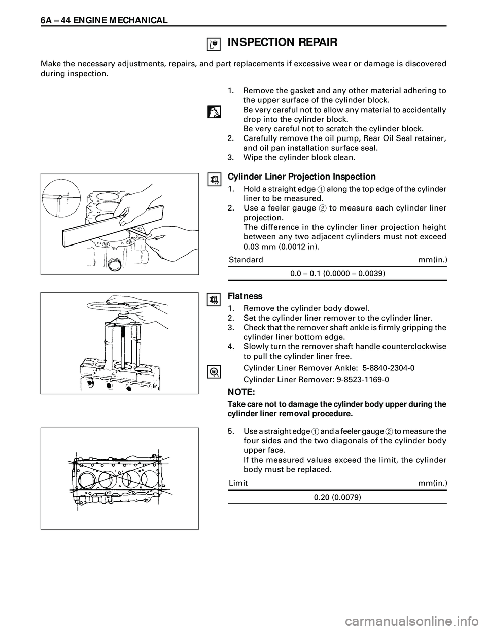
1. Hold a straight edge 1 along the top edge of the cylinder
liner to be measured.
2. Use a feeler gauge 2 to measure each cylinder liner
projection.
The difference in the cylinder liner projection height
between any two adjacent cylinders must not exceed
0.03 mm (0.0012 in).
0.0 – 0.1 (0.0000 – 0.0039)
mm(in.) Standard
Flatness
1. Remove the cylinder body dowel.
2. Set the cylinder liner remover to the cylinder liner.
3. Check that the remover shaft ankle is firmly gripping the
cylinder liner bottom edge.
4. Slowly turn the remover shaft handle counterclockwise
to pull the cylinder liner free.
Cylinder Liner Remover Ankle: 5-8840-2304-0
Cylinder Liner Remover: 9-8523-1169-0
NOTE:
Take care not to damage the cylinder body upper during the
cylinder liner removal procedure.
5. Use a straight edge 1 and a feeler gauge 2 to measure the
four sides and the two diagonals of the cylinder body
upper face.
If the measured values exceed the limit, the cylinder
body must be replaced.
0.20 (0.0079)
mm(in.) Limit
Page 1596 of 3573

6A Ð 46 ENGINE MECHANICAL
Cylinder bore
diameter average
1Liner outside
diameterLiner
Grade
97.001-97.010
(3.8189-3.8193)
97.011-97.020
(3.8193-3.8197)
97.021-97.030
(3.8197-3.8201)
97.031-97.040
(3.8201-3.8205)97.011-97.020
(3.8193-3.8197)
97.021-97.030
(3.8197-3.8201)
97.031-97.040
(3.8201-3.8205)
97.041-97.050
(3.8205-3.8209)
2
3
4
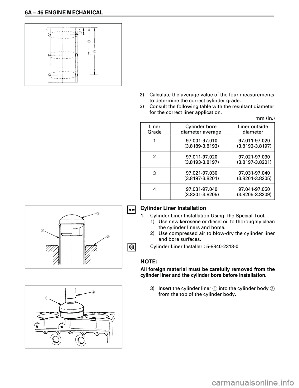
mm (in.) 2) Calculate the average value of the four measurements
to determine the correct cylinder grade.
3) Consult the following table with the resultant diameter
for the correct liner application.
Cylinder Liner Installation
1. Cylinder Liner Installation Using The Special Tool.
1) Use new kerosene or diesel oil to thoroughly clean
the cylinder liners and horse.
2) Use compressed air to blow-dry the cylinder liner
and bore surfaces.
Cylinder Liner Installer : 5-8840-2313-0
NOTE:
All foreign material must be carefully removed from the
cylinder liner and the cylinder bore before installation.
3) Insert the cylinder liner 1 into the cylinder body 2
from the top of the cylinder body.
Page 1600 of 3573

6A Ð 50 ENGINE MECHANICAL
8. Camshaft Timing Gear
1) Install the camshaft timing gear to the camshaft.
The timing gear mark ("Y - Y") must be facing
outword.
2) Tighten the timing gear to the specified torque.
64 (6.5/47)N·m (kg·m/lb·ft)
7. Oil Pump Assembly
·Refer to ÔOil pumpÕ in Section 6A2.
6. Crankcase Assembly
·Refer to ÔCrankcaseÕ in Section 6A2.
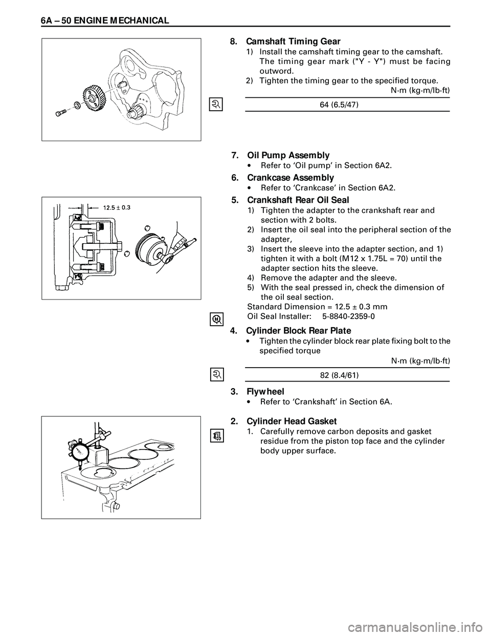
5. Crankshaft Rear Oil Seal
1) Tighten the adapter to the crankshaft rear and
section with 2 bolts.
2) Insert the oil seal into the peripheral section of the
adapter,
3) Insert the sleeve into the adapter section, and 1)
tighten it with a bolt (M12 x 1.75L = 70) until the
adapter section hits the sleeve.
4) Remove the adapter and the sleeve.
5) With the seal pressed in, check the dimension of
the oil seal section.
Standard Dimension = 12.5 ± 0.3 mm
Oil Seal Installer: 5-8840-2359-0
4. Cylinder Block Rear Plate
·Tighten the cylinder block rear plate fixing bolt to the
specified torque
82 (8.4/61)N·m (kg·m/lb·ft)
3. Flywheel
·Refer to ÔCrankshaftÕ in Section 6A.
2. Cylinder Head Gasket
1. Carefully remove carbon deposits and gasket
residue from the piston top face and the cylinder
body upper surface.
Page 1605 of 3573
4JG2-NA/4JG2-TURBO ENGINE 6A2 Ð 3
ENGINE MOUNT (RH)
REMOVAL
Preparation:
·Battery ground cable
·Support engine
·Support vehicle
1. Front Tire
2. Dust Cover
3. Engine Mount
·Remove fixing be its from cylinder body and
chassis frame.
INSTALLATION
3. Engine Mount
40 (4.1/30)
N·m(kg·m/lb·ft) Cylinder body side
40 (4.1/30)
N·m(kg·m/lb·ft) Chassis frame side
·Tighten the fixing bolts to the specified torque
2. Dust Cover
1. Front Tire
118 (12.0/87)N·m(kg·m/lb·ft)