Page 1635 of 3573
4JG2-NA/4JG2-TURBO ENGINE 6A2 Ð 33
OIL FILTER CARTRIDGE
REMOVAL
·Place a receptacle beneath the oil filter to contain the
drained oil.
·Remove the oil filter cartridge using filter wrench.
Filter wrench: 5-8840-0200-0
INSTALLATION
·Lightly oil the o-ring of oil filter cartridge.
·Turn in the new oil filter cartridge by hand until the
sealing face is fiffted again the o-ring.
·Use the filter wrench to turn in the oil filter and
additional one and 1á1/8 turns.
·Start the engine and check for oil leakage from oil filter.
Page 1636 of 3573
6A2 Ð 34 4JG2-NA/4JG2-TURBO ENGINE
OIL COOLER
REMOVAL
Preparation
·Disconnect battery ground cable
·Drain coolant
1. Air Cleaner Cover & Air Duct
2. Intercooler Assembly (4JG2-T Only)
·Refer to intercooler removal steps in this section
3. Front Exh. Pipe
·Disconnect front exhaust pipe from engine side
and intermediate pipe.
4. Heat Protector (4JG2-T Only)
5. Exh. Adapter (4JG2-T Only)
6. Oil Cooler
·Disconnect water inlet and outlet hose.
·Remove fixing bolts and oil cooler.
·Put rag to beneath side of oil cooler to prevent oil
leaking.
Page 1638 of 3573
6A2 Ð 36 4JG2-NA/4JG2-TURBO ENGINE
OIL PUMP ASSEMBLY
REMOVAL
Preparation
·Disconnect battery ground cable.
·Lift up car.
·Drain engine oil.
NOTE
·Install drain plug with new washer.
1. Crankcase
·Refer to crankcase removal steps in this section
2. Oil Pump Assembly
·Remove oil pump asm from cylinder block.
INSTALLATION
·Prepare a solution of 80% engine oil and 20% molyb-
denum disulfide.
·Apply and ample coat of the solution to the teeth of
the oil pump pinion.
2. Oil Pump Assembly
·Apply engine oil to oil pipe o-ring and insert the
o-ring in o-ring hold on cylinder block.
·Install oil pump asm with oil pipe in cylinder block
and tighten fixing bolts to the specified torque.
19 (1.9/14)N·m(Kg·m/lb·ft)
·Tighten sleeve nut to the specified torque.
25 (2.5/18)N·m(Kg·m/lb·ft)
1. Crankcase
·Refer to crankcase installation steps in this section
Page 1639 of 3573
4JG2-NA/4JG2-TURBO ENGINE 6A2 Ð 37
PISTON, PISTON RING AND CONNECTING ROD
REMOVAL
1. Cylinder Head
·Refer to ÒCylinder HeadÓ removal in this sec-
tion.
2. Crankcase
·Refer to ÒCrankcaseÓ in this section.
3. Connecting Rod Bearing Cap
·Before removing the bearing cap, remove
carbon on the top of cylinder bore.
4. Piston, Piston Rings and Connecting Rod
·Push piston and connecting rod out from the
top of cylinder bore.
INSTALLATION
4. Piston, Piston Rings and Connecting Rod
·Apply engine oil to cylinder bore, connecting
rod bearings and crank pins.
·In installing the piston, its front mark must face
the engine front side.
3. Connecting Rod Bearing Cap
·The bearing cap number must be same as
connecting rod number.
·Apply engine oil to the thread and sealing
surface of each nuts.
·Tighten nuts to the specified torque.
Page 1643 of 3573

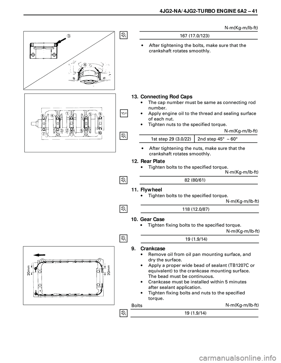
4JG2-NA/4JG2-TURBO ENGINE 6A2 Ð 41
19 (1.9/14)N·m(Kg·m/lb·ft)
·After tightening the bolts, make sure that the
crankshaft rotates smoothly.
167 (17.0/123)N·m(Kg·m/lb·ft)
13. Connecting Rod Caps
·The cap number must be same as connecting rod
number.
·Apply engine oil to the thread and sealing surface
of each nut.
·Tighten nuts to the specified torque.
·After tightening the nuts, make sure that the
crankshaft rotates smoothly.
12. Rear Plate
·Tighten bolts to the specified torque.
82 (80/61)N·m(Kg·m/lb·ft)
11. Flywheel
·Tighten bolts to the specified torque.
118 (12.0/87)N·m(Kg·m/lb·ft)
10. Gear Case
·Tighten fixing bolts to the specified torque.
19 (1.9/14)N·m(Kg·m/lb·ft)
9. Crankcase
·Remove oil from oil pan mounting surface, and
dry the surface.
·Apply a proper wide bead of sealant (TB1207C or
equivalent) to the crankcase mounting surface.
The bead must be continuous.
·Crankcase must be installed within 5 minutes
after sealant application.
·Tighten fixing bolts and nuts to the specified
torque.
Bolts
1st step 29 (3.0/22) 2nd step 45° – 60°N·m(Kg·m/lb·ft)
Page 1647 of 3573
4JG2-NA/4JG2-TURBO ENGINE 6A2 Ð 45
FRONT OIL SEAL
REMOVAL
1. Crankshaft Damper Pulley
2. Timing Gear Case Cover Assembly
3. Front Oil Seal
·Remove crankshaft front oil seal using suitable size
box wrench for push the oil seal from inside of
timing gear case cover.
INSTALLATION
3. Front Oil Seal
·Use the installer to install the front oil seal 1 to the
gear case cover 2.
Oil Seal Installer: 5-8840-2061-0
Note the oil seal installation depth 3 shown in the
illustration.
Depth 3 = 1 mm (0.039 in).
2. Timing Gear Case Cover Assembly
1) Align the timing gear case cover with the timing
gear case dowel pin then install the timing gear case
cover.
2) Tighten the timing gear case cover bolts to the
specified torque.
8 (0.8/69)N·m(Kg·m/lb·in)
1. Crankshaft Damper Pulley
Page 1648 of 3573
6A2 Ð 46 4JG2-NA/4JG2-TURBO ENGINE
REAR OIL SEAL
REMOVAL
1. Transmission Assembly
·Refer to ÒTransmissionÓ removal in section 7.
2. Flywheel
3. Rear Oil Seal
·With the oil seal pushed in deep, install the special
tool as shown in the illustration and remove the oil
seal.
Oil Seal Remover : 5-8840-2362-0
INSTALLATION
3. Rear Oil Seal
8. Crankshaft Rear Oil Seal
1) Tighten the adapter to the crankshaft rear and
section with 2 bolts.
2) Insert the oil seal into the peripheral section of the
adapter,
3) Insert the sleeve into the adapter section, and 1)
tighten it with a bolt (M12 x 1.75L = 70) until the
adapter section hits the sleeve.
4) Remove the adapter and the sleeve.
5) With the seal pressed in, check the dimension of
the oil seal section.
Standard Dimension = 12.5 ± 0.3 mm
Oil Seal Installer: 5-8840-2359-0
Page 1650 of 3573
6A2 Ð 48 4JG2-NA/4JG2-TURBO ENGINE
ENGINE ASSEMBLY
REMOVAL
Preparation
·Space stands and removal front tires.
·Removal battery. (two batteries for cold area)
·Drain coolant.
·Disconnect window washer hose and remove engine
hood.
1. Radiator Hose
·Disconnect upper and lower hoses from engine
side.
2. Fan Shroud
·Disengage clips and remove upper and lower fan
shrouds.