1998 ISUZU TROOPER Remove engine
[x] Cancel search: Remove enginePage 1692 of 3573
6D1 Ð 2 ENGINE ELECTRICAL
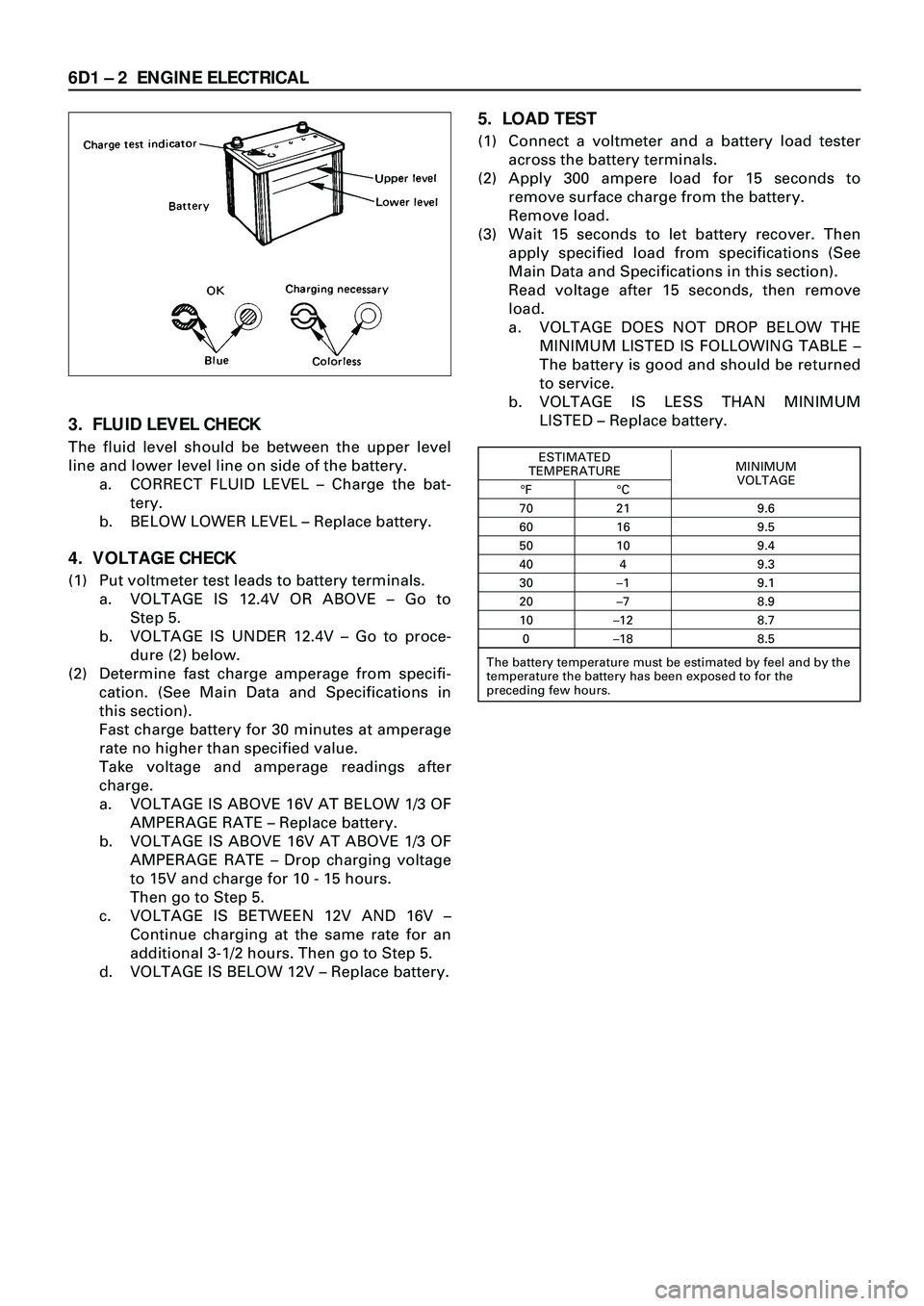
3. FLUID LEVEL CHECK
The fluid level should be between the upper level
line and lower level line on side of the battery.
a. CORRECT FLUID LEVEL Ð Charge the bat-
tery.
b. BELOW LOWER LEVEL Ð Replace battery.
4. VOLTAGE CHECK
(1) Put voltmeter test leads to battery terminals.
a. VOLTAGE IS 12.4V OR ABOVE Ð Go to
Step 5.
b. VOLTAGE IS UNDER 12.4V Ð Go to proce-
dure (2) below.
(2) Determine fast charge amperage from specifi-
cation. (See Main Data and Specifications in
this section).
Fast charge battery for 30 minutes at amperage
rate no higher than specified value.
Take voltage and amperage readings after
charge.
a. VOLTAGE IS ABOVE 16V AT BELOW 1/3 OF
AMPERAGE RATE Ð Replace battery.
b. VOLTAGE IS ABOVE 16V AT ABOVE 1/3 OF
AMPERAGE RATE Ð Drop charging voltage
to 15V and charge for 10 - 15 hours.
Then go to Step 5.
c. VOLTAGE IS BETWEEN 12V AND 16V Ð
Continue charging at the same rate for an
additional 3-1/2 hours. Then go to Step 5.
d. VOLTAGE IS BELOW 12V Ð Replace battery.
5. LOAD TEST
(1) Connect a voltmeter and a battery load tester
across the battery terminals.
(2) Apply 300 ampere load for 15 seconds to
remove surface charge from the battery.
Remove load.
(3) Wait 15 seconds to let battery recover. Then
apply specified load from specifications (See
Main Data and Specifications in this section).
Read voltage after 15 seconds, then remove
load.
a. VOLTAGE DOES NOT DROP BELOW THE
MINIMUM LISTED IS FOLLOWING TABLE Ð
The battery is good and should be returned
to service.
b. VOLTAGE IS LESS THAN MINIMUM
LISTED Ð Replace battery.
ESTIMATED
MINIMUM
TEMPERATURE
VOLTAGE
¡F ¡C
70 21 9.6
60 16 9.5
50 10 9.4
40 4 9.3
30 Ð1 9.1
20 Ð7 8.9
10 Ð12 8.7
0 Ð18 8.5
The battery temperature must be estimated by feel and by the
temperature the battery has been exposed to for the
preceding few hours.
Page 1693 of 3573
ENGINE ELECTRICAL 6D1 Ð 3
BATTERY CHARGING
Observe the following safety precautions when
charging the battery:
1. Never attempt to charge the battery when the
fluid level is below the lower level line on the
side of the battery. In this case, the battery
must be replaced.
2. Pay close attention to the battery during the
charging procedure.
Battery charging should be discontinued or the
rate of charge reduced if the battery feels hot to
the touch.
Battery charging should be discontinued or the
rate of charge reduced if the battery begins to
gas or spew electrolyte from the vent holes.
3. In order to more easily view the hydrometer
blue dot or ring, it may be necessary to jiggle or
tilt the battery.
4. Battery temperature can have a great effect on
battery charging capacity.
5. The sealed battery used on this vehicle may be
either quick-charged or slow-charged in the
same manner as other batteries.
Whichever method you decide to use, be sure
that you completely charge the battery. Never
partially charge the battery.
JUMP STARTING
JUMP STARTING WITH AN AUXILIARY
(BOOSTER) BATTERY
CAUTION:
Never push or tow the vehicle in an attempt to
start it. Serious damage to the emission system
as well as other vehicle parts will result.
Treat both the discharged battery and the
booster battery with great care when using
jumper cables. Carefully follow the jump
starting procedure, being careful at all times to
avoid sparking.
WARNING:
Failure to carefully follow the jump starting
procedure could result in the following:
1. Serious personal injury, particulaly to
your eyes.
2. Property damage from a battery explo-
sion, battery acid, or an electrical fire.
3. Damage to the electronic components of
one or both vehicles particularly. Never expose the battery to an open flame or elec-
trical spark. Gas generated by the battery may catch
fire or explode.
Remove any rings, watches, or other jewelry before
working around the battery. Protect your eyes by
wearing an approved set of goggles.
Never allow battery fluid to come in contact with
your eyes or skin.
Never allow battery fluid to come in contact with
fabrics or painted surfaces.
Battery fluid is a highly corrosive acid.
Should battery fluid come in contact with your
eyes, skin, fabric, or a painted surface, immediately
and thoroughly rinse the affected area with clean
tap water.
Never allow metal tools or jumper cables to come
in contact with the positive battery terminal, or any
other metal surface of the vehicle. This will protect
against a short circuit.
Always keep batteries out of the reach of young
children.
JUMP STARTING PROCEDURE
1. Set the vehicle parking brake.
If the vehicle is equipped with an automatic
transmission, place the selector lever in the
ÒPARKÓ position.
If the vehicle is equipped with a manual trans-
mission place the shift lever in the ÒNEUTRALÓ
position.
Turn ÒOFFÓ the ignition.
Turn ÒOFFÓ all lights and any other accessory
requiring electrical power.
2. Look at the built-in hydrometer.
If the indication area of the built-in hydrometer
is completely clear, do not try to jump start.
3. Attach the end of one jumper cable to the posi-
tive terminal of the booster battery.
Attach the other end of the same cable to the
positive terminal of the discharged battery.
Do not allow the vehicles to touch each other.
This will cause a ground connection, effectively
neutralizing the charging procedure.
Be sure that the booster battery has a 12 volt
rating.
4. Attach one end of the remaining cable to the
negative terminal of the booster battery.
Attach the other end of the same cable to a
solid engine ground (such as the A/C com-
pressor bracket or the generator mounting
bracket) of the vehicle with the discharged bat-
tery.
This ground connection must be at least 450
mm (18 in) from the battery of the vehicle
whose battery is being charged.
ON-VEHICLE SERVICE
Page 1694 of 3573
6D1 Ð 4 ENGINE ELECTRICAL
WARNING:
Never attach the end of the jumper cable
directly to the negative terminal of the dead
battery.
5. Start the engine of the vehicle with the good
battery.
Make sure that all unnecessary electrical acces-
sories have been turned ÒOFFÓ.
6. Start the engine of the vehicle with the dead
battery.
7. To remove the jumper cables, follow the above
directions in the reverse order.
Be sure to first disconnect the negative cable
from the vehicle with the discharged battery.
REMOVAL AND INSTALLATION OF THE
BATTERY
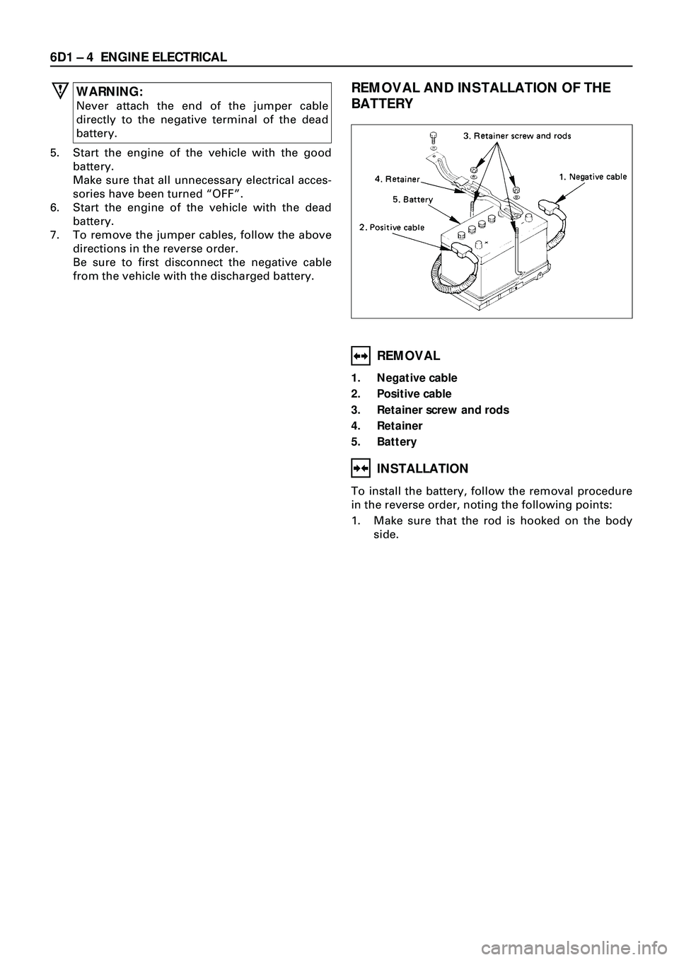
REMOVAL
1. Negative cable
2. Positive cable
3. Retainer screw and rods
4. Retainer
5. Battery
INSTALLATION
To install the battery, follow the removal procedure
in the reverse order, noting the following points:
1. Make sure that the rod is hooked on the body
side.
Page 1728 of 3573
6F Ð 4 ENGINE EXHAUST
2. Front exhaust pipe fixing nuts
¥ Remove two bolts fixed from front pipe and center
pipe A.
3. Exhaust manifold fixing nuts
¥ Remove two fixing nuts from exhaust manifold and
front pipe.
4. Front exhaust pipe
INSTALLATION
4. Front exhaust pipe
3. Exhaust manifold fixing nuts
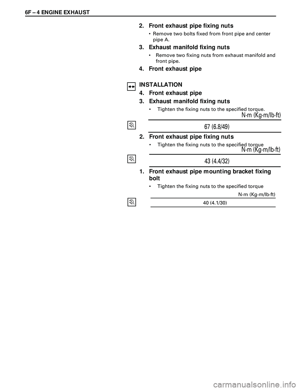
¥ Tighten the fixing nuts to the specified torque.
67 (6.8/49)N·m (Kg·m/lb·ft)
2. Front exhaust pipe fixing nuts
¥ Tighten the fixing nuts to the specified torque
43 (4.4/32)N·m (Kg·m/lb·ft)
1. Front exhaust pipe mounting bracket fixing
bolt
¥ Tighten the fixing nuts to the specified torque
40 (4.1/30)N·m (Kg·m/lb·ft)
Page 1729 of 3573
ENGINE EXHAUST 6F Ð 5
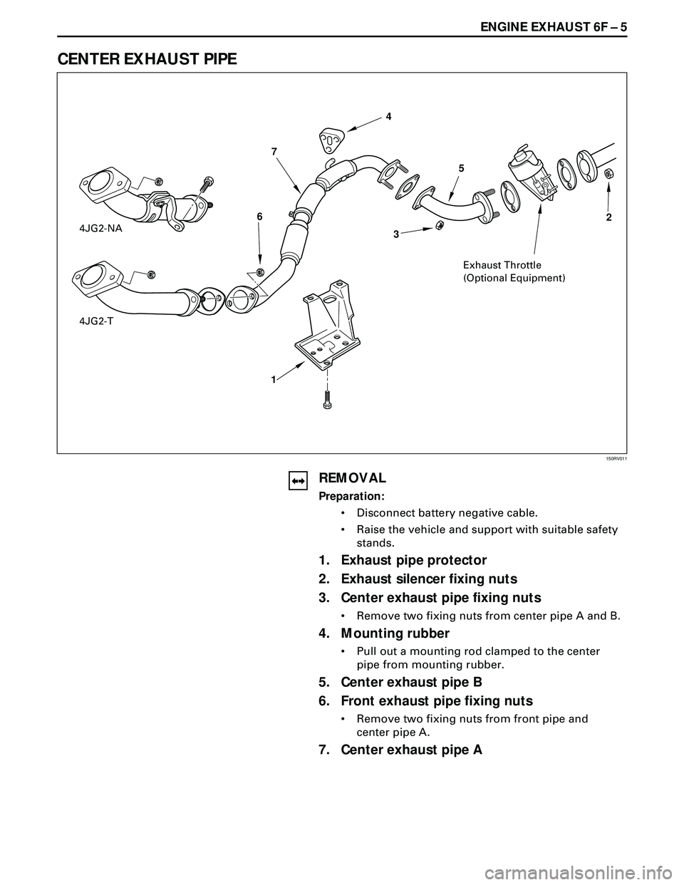
CENTER EXHAUST PIPE
REMOVAL
Preparation:
¥ Disconnect battery negative cable.
¥ Raise the vehicle and support with suitable safety
stands.
1. Exhaust pipe protector
2. Exhaust silencer fixing nuts
3. Center exhaust pipe fixing nuts
¥ Remove two fixing nuts from center pipe A and B.
4. Mounting rubber
¥ Pull out a mounting rod clamped to the center
pipe from mounting rubber.
5. Center exhaust pipe B
6. Front exhaust pipe fixing nuts
¥ Remove two fixing nuts from front pipe and
center pipe A.
7. Center exhaust pipe A
150RV011
4JG2-NA
Exhaust Throttle
(Optional Equipment) 7
1 64
5
32
4JG2-T
Page 1733 of 3573
ENGINE EXHAUST 6F Ð 9
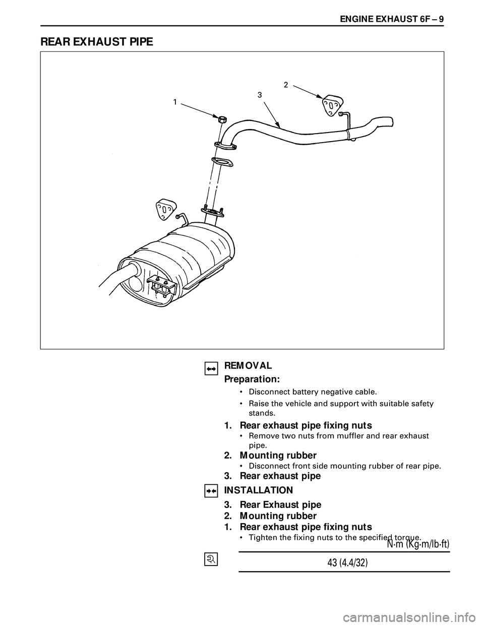
REAR EXHAUST PIPE
REMOVAL
Preparation:
¥ Disconnect battery negative cable.
¥ Raise the vehicle and support with suitable safety
stands.
1. Rear exhaust pipe fixing nuts
¥ Remove two nuts from muffler and rear exhaust
pipe.
2. Mounting rubber
¥ Disconnect front side mounting rubber of rear pipe.
3. Rear exhaust pipe
INSTALLATION
3. Rear Exhaust pipe
2. Mounting rubber
1. Rear exhaust pipe fixing nuts
¥ Tighten the fixing nuts to the specified torque.
43 (4.4/32)N·m (Kg·m/lb·ft)
2
3
1
Page 1744 of 3573
ENGINE MECHANICAL 6A – 11
Remove the radiator filler cap only when absolutely
necessary.
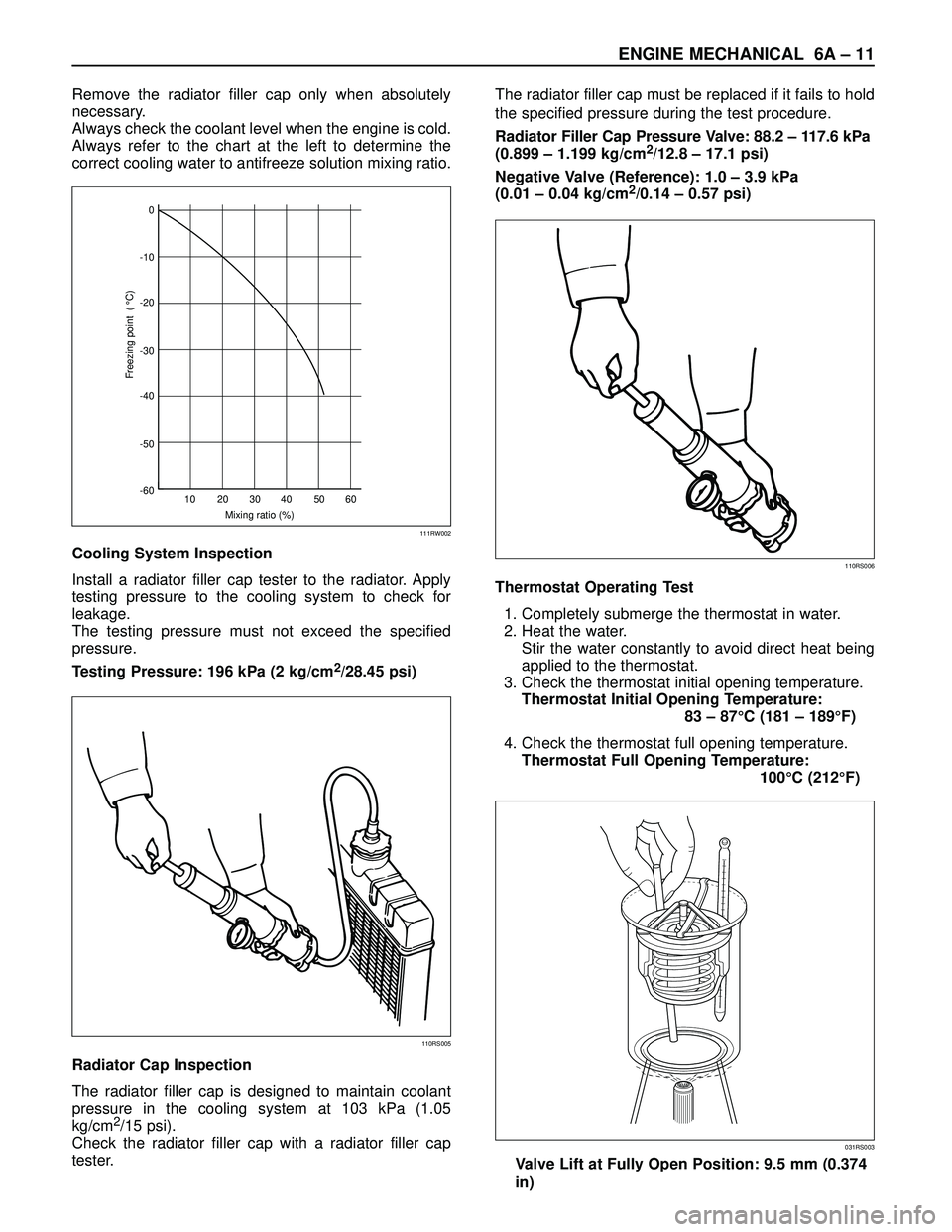
Always check the coolant level when the engine is cold.
Always refer to the chart at the left to determine the
correct cooling water to antifreeze solution mixing ratio.
Cooling System Inspection
Install a radiator filler cap tester to the radiator. Apply
testing pressure to the cooling system to check for
leakage.
The testing pressure must not exceed the specified
pressure.
Testing Pressure: 196 kPa (2 kg/cm
2/28.45 psi)
Radiator Cap Inspection
The radiator filler cap is designed to maintain coolant
pressure in the cooling system at 103 kPa (1.05
kg/cm
2/15 psi).
Check the radiator filler cap with a radiator filler cap
tester.The radiator filler cap must be replaced if it fails to hold
the specified pressure during the test procedure.
Radiator Filler Cap Pressure Valve: 88.2 – 117.6 kPa
(0.899 – 1.199 kg/cm
2/12.8 – 17.1 psi)
Negative Valve (Reference): 1.0 – 3.9 kPa
(0.01 – 0.04 kg/cm
2/0.14 – 0.57 psi)
Thermostat Operating Test
1. Completely submerge the thermostat in water.
2. Heat the water.
Stir the water constantly to avoid direct heat being
applied to the thermostat.
3. Check the thermostat initial opening temperature.
Thermostat Initial Opening Temperature:
83 – 87°C (181 – 189°F)
4. Check the thermostat full opening temperature.
Thermostat Full Opening Temperature:
100°C (212°F)
Valve Lift at Fully Open Position: 9.5 mm (0.374
in)0
-10
-20
-30
-40
-50
-60
10 20 30
Mixing ratio (%)
Freezing point ( °C)
40 50 60
111RW002
110RS005
110RS006
031RS003
Page 1746 of 3573
ENGINE MECHANICAL 6A – 13
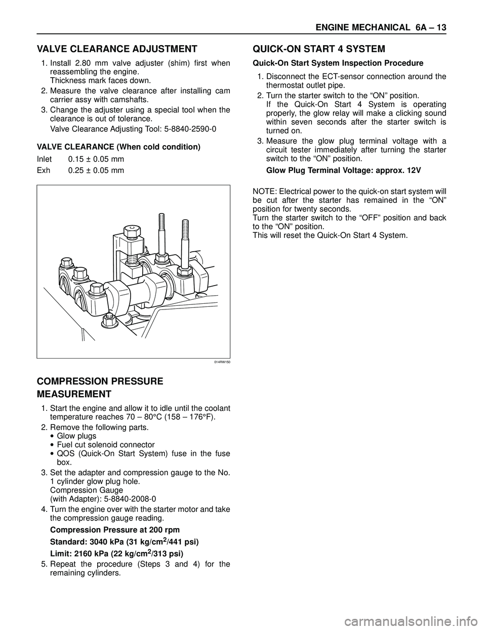
VALVE CLEARANCE ADJUSTMENT
1. Install 2.80 mm valve adjuster (shim) first when
reassembling the engine.
Thickness mark faces down.
2. Measure the valve clearance after installing cam
carrier assy with camshafts.
3. Change the adjuster using a special tool when the
clearance is out of tolerance.
Valve Clearance Adjusting Tool: 5-8840-2590-0
VALVE CLEARANCE (When cold condition)
Inlet 0.15 ± 0.05 mm
Exh 0.25 ± 0.05 mm
COMPRESSION PRESSURE
MEASUREMENT
1. Start the engine and allow it to idle until the coolant
temperature reaches 70 – 80°C (158 – 176°F).
2. Remove the following parts.
•Glow plugs
•Fuel cut solenoid connector
•QOS (Quick-On Start System) fuse in the fuse
box.
3. Set the adapter and compression gauge to the No.
1 cylinder glow plug hole.
Compression Gauge
(with Adapter): 5-8840-2008-0
4. Turn the engine over with the starter motor and take
the compression gauge reading.
Compression Pressure at 200 rpm
Standard: 3040 kPa (31 kg/cm
2/441 psi)
Limit: 2160 kPa (22 kg/cm
2/313 psi)
5. Repeat the procedure (Steps 3 and 4) for the
remaining cylinders.
QUICK-ON START 4 SYSTEM
Quick-On Start System Inspection Procedure
1. Disconnect the ECT-sensor connection around the
thermostat outlet pipe.
2. Turn the starter switch to the “ON” position.
If the Quick-On Start 4 System is operating
properly, the glow relay will make a clicking sound
within seven seconds after the starter switch is
turned on.
3. Measure the glow plug terminal voltage with a
circuit tester immediately after turning the starter
switch to the “ON” position.
Glow Plug Terminal Voltage: approx. 12V
NOTE: Electrical power to the quick-on start system will
be cut after the starter has remained in the “ON”
position for twenty seconds.
Turn the starter switch to the “OFF” position and back
to the “ON” position.
This will reset the Quick-On Start 4 System.
014RW150