Page 1769 of 3573
6A – 36 ENGINE MECHANICAL
EXHAUST MANIFOLD
9
598 For Europe875 63
21
4
7
4
2
1
36
025R200004
Legend
(1) Exhaust Manifold
(2) Gasket
(3) Turbocharger Assembly
(4) Water Hose(5) Water Hose
(6) Heat Protector
(7) Oil Pipe
(8) Oil Pipe
(9) Gasket
REMOVAL
1. Remove the hose from both turbocharger outlet and
intake manifold inlet side, then remove intercooler
assembly.
2. Loosen belt tensioner, remove A/C compressor
assembly.
3. Remove heat protector from turbocharger.
4. Remove water hoses and oil pipes from
turbocharger.
5. Remove turbocharger assembly from exhaustmanifold.
6. Remove exhaust manifold fixing nuts, then remove
exhaust manifold.
Page 1772 of 3573
ENGINE MECHANICAL 6A – 39
REMOVAL
1. Remove battery.
2. Drain engine coolant.
3. Remove air cleaner cover with air duct.
4. Remove intercooler assembly.
Refer to “Intercooler” in this manual.
5. Remove water pipe for turbocharger inlet.
6. Remove oil pipe for turbocharger.
1) Remove eye bolt from turbocharger.
2) Plug oil port on the turbocharger to prevent entry
of foreign materials.
7. Remove oil drain pipe from turbocharger.
8. Remove water outlet pipe.
9. Remove heat protector.
10. Remove exhaust adaptor.
11. Remove turbocharger assembly from exhaust
manifold.
For Europe
025R200006
Page 1774 of 3573
ENGINE MECHANICAL 6A – 41
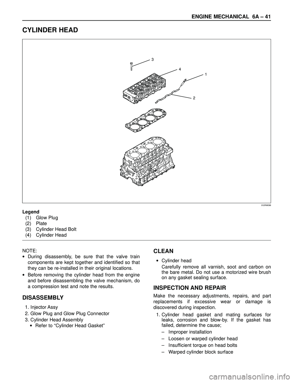
CYLINDER HEAD
3
4
1
2
012RW096
Legend
(1) Glow Plug
(2) Plate
(3) Cylinder Head Bolt
(4) Cylinder Head
NOTE:
•During disassembly, be sure that the valve train
components are kept together and identified so that
they can be re-installed in their original locations.
•Before removing the cylinder head from the engine
and before disassembling the valve mechanism, do
a compression test and note the results.
DISASSEMBLY
1. Injector Assy
2. Glow Plug and Glow Plug Connector
3. Cylinder Head Assembly
•Refer to “Cylinder Head Gasket”
CLEAN
•Cylinder head
Carefully remove all varnish, soot and carbon on
the bare metal. Do not use a motorized wire brush
on any gasket sealing surface.
INSPECTION AND REPAIR
Make the necessary adjustments, repairs, and part
replacements if excessive wear or damage is
discovered during inspection.
1. Cylinder head gasket and mating surfaces for
leaks, corrosion and blow-by. If the gasket has
failed, determine the cause;
–Improper installation
–Loosen or warped cylinder head
–Insufficient torque on head bolts
–Warped cylinder block surface
Page 1777 of 3573
6A – 44 ENGINE MECHANICAL
REMOVAL
1. Disconnect battery ground cable.
2. Drain engine coolant.
3. Remove air cleaner and air duct.
4. Remove intercooler assembly.
Refer to “Intercooler” in this manual.
5. Remove oil level gauge guide assembly.
6. Remove PCV hose.
7. Remove EGR vacuum hose.
8. Disconnect harness connector around the cylinder
head.
9. Remove A/C compressor assembly.
10. Remove A/C compressor bracket.
11. Remove generator assembly and take out fan belt.
12. Remove heat protector and remove valve
assembly.
13. Remove water hose and oil pipe from turbocharger.
14. Remove turbocharger assembly.
15. Remove water hose between thermostat and
radiator.
16. Remove cylinder head noise insulator cover.
NOTE: Do not make damage to the harness.
17. Remove high pressure pipe.
18. Remove timing belt cover.
19. Remove CMP sensor bracket.
20. Remove timing belt tensioner and remove timing
belt.
21. Remove camshaft pulley.
22. Remove front plate.
23. Remove water pipe between cylinder head and
water pump.
24. Remove fuel pipe between fuel pump and intake
manifold.
25. Remove fuel return pipe.
26. Remove intake manifold assembly.
27. Disconnect glow plug wiring and remove glow plug.
28. Remove cylinder head cover.
29. Drain oil from oil rail.
30. Disconnect injector harness connector.
31. Disconnect harness connector from oil pressure
sensor and oil temperature sensor on the oil rail.
32. Disconnect injector harness assembly.
33. Remove injector clamp.
34. Remove injector spacer (If equipped.).
35. Remove injector assembly.
36. Remove oil rail assembly.
37. Remove camshaft carrier.
38. Remove cylinder head assembly.
39. Remove cylinder gasket.
INSTALLATION
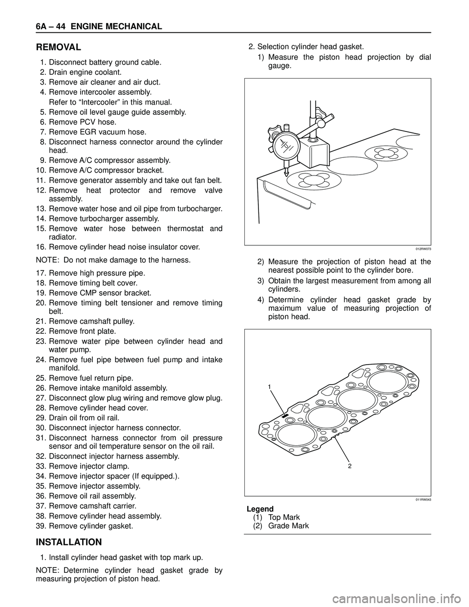
1. Install cylinder head gasket with top mark up.
NOTE: Determine cylinder head gasket grade by
measuring projection of piston head.2. Selection cylinder head gasket.
1) Measure the piston head projection by dial
gauge.
2) Measure the projection of piston head at the
nearest possible point to the cylinder bore.
3) Obtain the largest measurement from among all
cylinders.
4) Determine cylinder head gasket grade by
maximum value of measuring projection of
piston head.
Legend
(1) Top Mark
(2) Grade Mark
012RW073
2 1
011RW043
Page 1781 of 3573
6A – 48 ENGINE MECHANICAL
DISASSEMBLY
1. Injector clamp
2. Injector assembly
3. Oil rail assembly
4. Camshaft bracket
5. Camshaft
6. Oil seal
7. Plug
NOTE: Before starting disassembly above, drain oil
from oil rail to prevent oil from entering the cylinder.
REASSEMBLY
1. Camshaft
1) Before reassembling the camshaft to the
camshaft carrier, align the holes between the
main gear and the sub gear on the intake side of
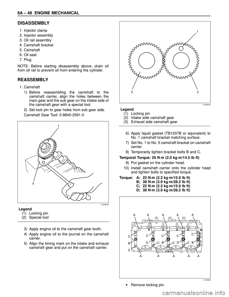
the camshaft gear with a special tool.
2) Set lock pin to gear holes from sub gear side.
Camshaft Gear Tool: 5-8840-2591-0
Legend
(1) Locking pin
(2) Special tool
3) Apply engine oil to the camshaft gear tooth.
4) Apply engine oil to the journal on the camshaft
carrier.
5) Align the timing mark on the intake and exhaust
camshaft gear and put on the camshaft carrier.Legend
(1) Locking pin
(2) Intake side camshaft gear
(3) Exhaust side camshaft gear
6) Apply liquid gasket (TB1207B or equivalent) to
No. 1 camshaft bracket matching surface.
7) Set No. 1 to No. 5 camshaft bracket on camshaft
carrier.
8) Temporarily tighten bracket bolts B and C.
Temporal Torque: 20 N·m (2.0 kg·m/14.5 lb ft)
9) Put gasket on the cylinder head.
10) Install camshaft carrier onto the cylinder head
and tighten bolts to specified torque.
Torque: A; 22 N·m (2.2 kg·m/15.9 lb ft)
B; 38 N·m (3.9 kg·m/28.2 lb ft)
C; 22 N·m (2.2 kg·m/15.9 lb ft)
D; 38 N·m (3.9 kg·m/28.2 lb ft)
•Remove locking pin.
1
2
014RW183
321
014RW184
CC
D
B
CC
B
CC
D
CC
B
C
A AA A A A
AAAA
011RW035
Page 1783 of 3573
6A – 50 ENGINE MECHANICAL
NOTE: Do not allow the camshaft to rotate.
6) Remove the camshaft bracket and measure the
plastigauge width and determine the oil
clearance. If the oil clearance exceeds the
specified limit, replace the camshaft carrier
and/or camshaft.
Oil clearance.
Standard: 0.040 – 0.082 mm (0.0016 – 0.0032 in)
Limit: 0.12 mm (0.0047 in)
7) Clean the plastigauge from the camshaft bracket
and camshaft carrier.
5. Camshaft thrust clearance.
1) Clean the camshaft, camshaft bracket and
camshaft carrier.
2) Put camshaft carrier on the cylinder head.
3) Put camshaft on the camshaft carrier.
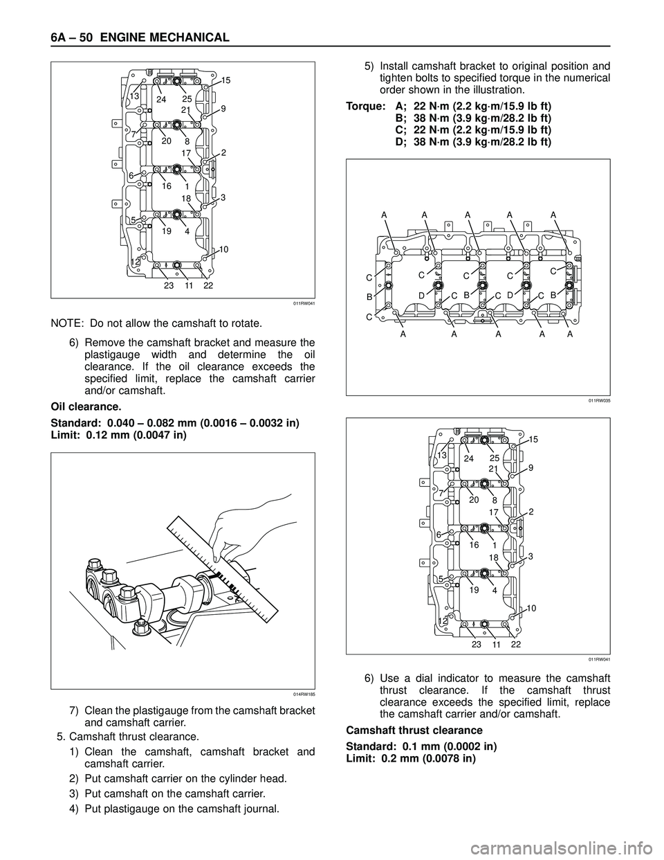
4) Put plastigauge on the camshaft journal.5) Install camshaft bracket to original position and
tighten bolts to specified torque in the numerical
order shown in the illustration.
Torque: A; 22 N·m (2.2 kg·m/15.9 lb ft)
B; 38 N·m (3.9 kg·m/28.2 lb ft)
C; 22 N·m (2.2 kg·m/15.9 lb ft)
D; 38 N·m (3.9 kg·m/28.2 lb ft)
6) Use a dial indicator to measure the camshaft
thrust clearance. If the camshaft thrust
clearance exceeds the specified limit, replace
the camshaft carrier and/or camshaft.
Camshaft thrust clearance
Standard: 0.1 mm (0.0002 in)
Limit: 0.2 mm (0.0078 in)
13
7
6
5
1215
2
3
10
9
20
8
19
2322
4
161
11 25
24
21
17
18
011RW041
014RW185
CC
D
B
CC
B
CC
D
CC
B
C
A AA A A A
AAAA
011RW035
13
7
6
5
1215
2
3
10
9
20
8
19
2322
4
161
11 25
24
21
17
18
011RW041
Page 1785 of 3573
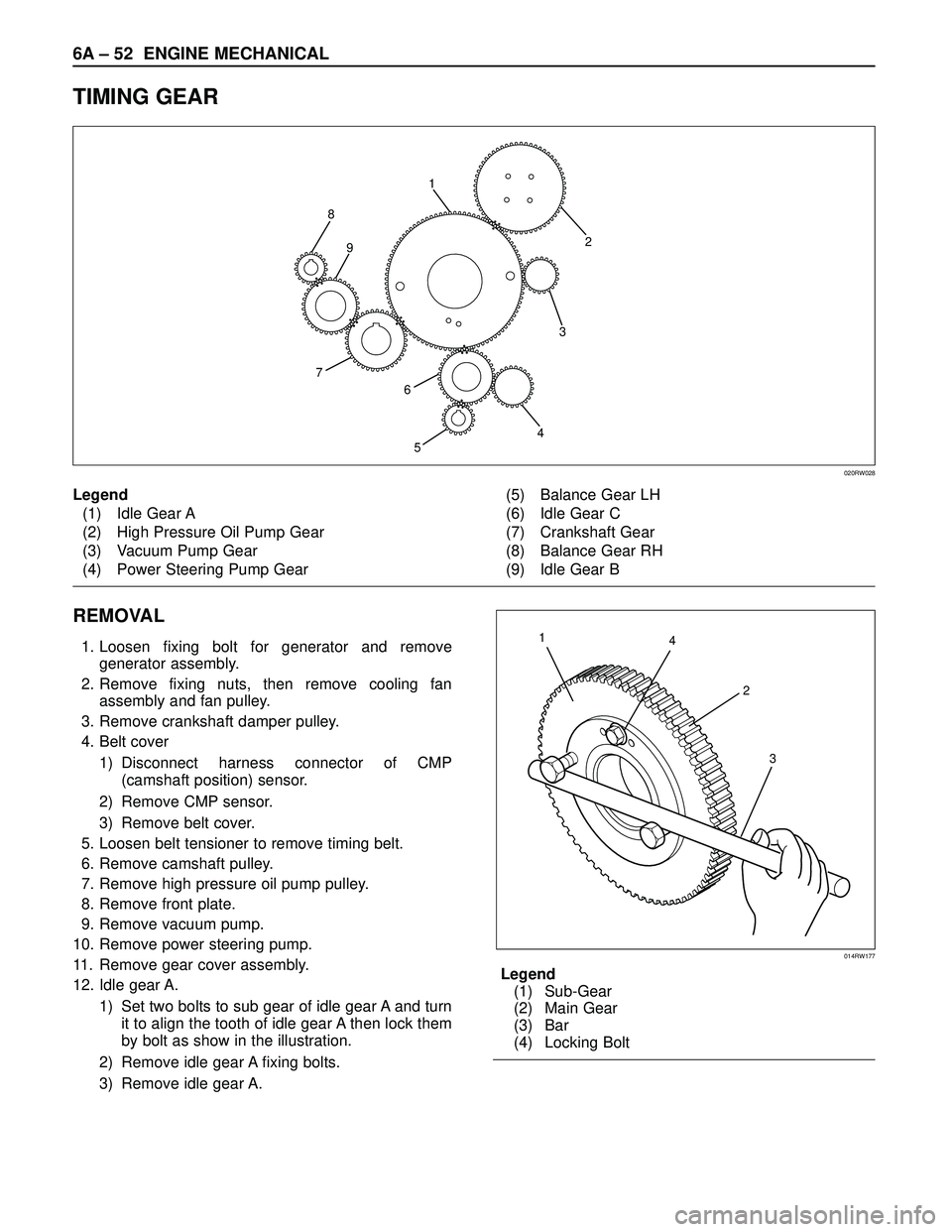
6A – 52 ENGINE MECHANICAL
TIMING GEAR
REMOVAL
1. Loosen fixing bolt for generator and remove
generator assembly.
2. Remove fixing nuts, then remove cooling fan
assembly and fan pulley.
3. Remove crankshaft damper pulley.
4. Belt cover
1) Disconnect harness connector of CMP
(camshaft position) sensor.
2) Remove CMP sensor.
3) Remove belt cover.
5. Loosen belt tensioner to remove timing belt.
6. Remove camshaft pulley.
7. Remove high pressure oil pump pulley.
8. Remove front plate.
9. Remove vacuum pump.
10. Remove power steering pump.
11. Remove gear cover assembly.
12. Idle gear A.
1) Set two bolts to sub gear of idle gear A and turn
it to align the tooth of idle gear A then lock them
by bolt as show in the illustration.
2) Remove idle gear A fixing bolts.
3) Remove idle gear A.Legend
(1) Sub-Gear
(2) Main Gear
(3) Bar
(4) Locking Bolt
2
3
4
5 8
7
6 91
020RW028
Legend
(1) Idle Gear A
(2) High Pressure Oil Pump Gear
(3) Vacuum Pump Gear
(4) Power Steering Pump Gear(5) Balance Gear LH
(6) Idle Gear C
(7) Crankshaft Gear
(8) Balance Gear RH
(9) Idle Gear B
4 1
2
3
014RW177
Page 1786 of 3573
ENGINE MECHANICAL 6A – 53
Legend
(1) Bolt
(2) Retainer
(3) Idle Gear A
(4) Idle Gear A Shaft
(5) Align Mark
(6) Crankshaft Gear
(7) O-Ring
13. Idle gear C
1) Use the special tool on idle gear C, turning the
sub gear to align the teeth, then set lock pin.
2) Remove idle gear C fixing bolt then remove the
idle gear C with flange.
Camshaft Gear Tool : 5-8840-2591-0
Legend
(1) Lock pin
(2) Camshaft Gear ToolLegend
(1) Bolt
(2) Retainer
(3) Idle Gear C
(4) Idle Gear C Shaft
(5) Align Mark
(6) Align Mark
(7) Idle Gear A
(8) Balance Shaft Gear LH
(9) Timing Mark
14. Idle gear B
1) Loosen idle gear B fixing bolt to remove idle
gear B with flange.
Legend
(1) Bolt
(2) Retainer
(3) Idle Gear B
(4) Idle Gear B Shaft
(5) Align Mark
3
6
5
4
3
2
1 7 1
7
014R200007
1
2
014RW181
12345 56
6 8
8 37
7
9
99
014RW175
35
5
4
3
2
1
014R200008