Page 1651 of 3573

4JG2-NA/4JG2-TURBO ENGINE 6A2 Ð 49
3. Cooling Fan Assembly
·Remove cooling fan asm fixing nuts, cooling fan
asm, fan pulley and center.
4. Radiator Assembly
·Remove bracket and radiator asm.
5. Air Cleaner Cover & Air Duct
6. Intercooler Assembly (4JG2 -T only)
·(Refer to Intercooler removal steps in this section)
7. P/S Pump Drive Belts
·Loosen P/S pump fixing bolts and adjusting bolt
and remove two drive belts.
8. P/S Pump Assembly
·Remove two fixing bolts (front side), a fixing nut
(rear side) and support P/S pump asm with oil
hoses by tying to body side.
9. Engine Ground Cable
·Disconnect ground cable from A/C compressor
bracket.
10. AC Generator Harness
·Disconnect B terminal and harness connector
from AC generator.
11. A/C Compressor Assembly
·Remove A/C compressor fixing bolt (rear under
side of compressor) by using a long extension bar
at under side of wheel arch.
·Disconnect magnetic clutch harness connector.
·Remove fixing bolts (upper and front lower side
of compressor) and set A/C compressor asm with
pipe lines on battery carrier.
12. Vacuum Hose: Vacuum Pump
·Disconnect vacuum hose from vacuum pump.
13. Starter Harness
·Disconnect B terminal and put cable harness close
to chassis side.
·Disconnect S terminal connector.
14. Engine Harness.
·Disconnect engine harness close to engine side.
15. Accelerater Cable
·Loosen locking nut at bracket and disconnect
accelerater cable from injection pump control
lever.
16. Fuel Hoses
·Disconnect fuel hoses from injection pump side
and take care not to spill fuel and enter dust.
17. Engine Ground Cable
·Disconnect ground cable from left rear side of
timing gear case.
Page 1652 of 3573

6A2 Ð 50 4JG2-NA/4JG2-TURBO ENGINE
18. Vacuum Hose : Vacuum Tank
·Disconnect vacuum hose from vacuum pump
side.
19. Glow Plug Harness
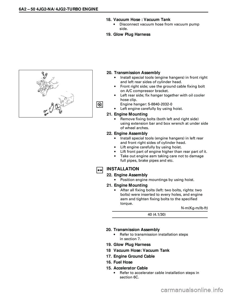
20. Transmission Assembly
·Install special tools (engine hangers) in front right
and left rear sides of cylinder head.
·Front right side; use the ground cable fixing bolt
on A/C compressor bracket.
·Left rear side; fix hanger together with oil cooler
hose clip.
Engine hanger: 5-8840-2032-0
·Left engine carefully by using hoist.
21. Engine Mounting
·Remove fixing bolts (both left and right side)
using extension bar and box wrench at under side
of wheel arches.
22. Engine Assembly
·Install special tools (engine hangers) in left rear
and front right sides of cylinder head.
·Lift engine carefully by using hoist.
·Lift front part of engine higher than rear part of it.
·Take out engine asm taking care not to damage
full pipes, brake pipes and etc.
INSTALLATION
22. Engine Assembly
·Position engine mountings by using hoist.
21. Engine Mounting
·After all fixing bolts (left: two bolts, rights: two
bolts) were inserted to every holes, and engine
asm and tighten fixing bolts to the specified
torque.
40 (4.1/30)N·m(Kg·m/lb·ft)
20. Transmission Assembly
·Refer to transmission installation steps
in section 7.
19. Glow Plug Harness
18 Vacuum Hose: Vacuum Tank
17. Engine Ground Cable
16. Fuel Hose
15. Accelerator Cable
·Refer to accelerater cable installation steps in
section 6C.
Page 1659 of 3573
ENGINE COOLING 6B Ð 5
ON-VEHICLE SERVICE
WATER PUMP
REMOVAL
Preparation
·Drain coolant.
1. P/S pump Drive Belts
·Loosen P/S pump mounting bolt, loosen adjust
bolts and remove the drive belts.
2. AC Generator Drive Belt
·Loosen AC Generator mounting bolt (bottom
side), adjust plate lock bolt, and remove the drive
belt.
3. Cooling Fan Assembly
·Remove lock nut and take out cooling fan
assembly, distance piece, and fan pulley.
4. Crankshaft Damper Pulley.
5. Gear Case Cover.
6. Water Pump Assembly
7. O-ring
INSPECTION
Make necessary repair and parts replacement if extreme
wear or damage is found during inspection. Should any
of the following problems occur, the entire water pump
assembly must be replaced.
·Cracks in the coolant pump body
·Coolant leakage from the seal unit
·Play or abnormal noise in the bearing
·Cracks or corrosion in the impeller
Page 1661 of 3573
ENGINE COOLING 6B Ð 7
THERMOSTAT
REMOVAL
Preparation
·Disconnect battery ground cable.
·Drain coolant from the radiator and engine.
1. Water Hose; Turbocharger (4JG2-T Only)
2. Outlet Pipe
·Remove mounting bolt and remove outlet pipe
together with radiator hose.
3. Gasket
4. Thermostat
INSPECTION
Submerge the thermostat assembly in the water.
Place wooden blocks on the bottom of the water
container.
Not to directly heat the thermostat.
Gradually increase the water temperature. Stir the water
so that the entire water is same temperature.
·Make sure that primary valve begins to open at the
specified temperature.
82 (180 )
°C (°F) Valve Opening Temperature
Page 1663 of 3573
ENGINE COOLING 6B Ð 9
RADIATOR
REMOVAL
Preparation
·Disconnect battery ground cable.
·Loosen drain plug to drain coolant.
1. Radiator Hose
·Disconnect lower hose and upper hose from the
engine.
2. Fan Guide Lower
·Remove clips on both sides and the bottom lock.
3. Reservoir Tank Hose
·Disconnect the hose from radiator.
4. Bracket
5. Radiator Assembly
·Remove upward the radiator assembly with hose,
taking care not to damage the radiator core by fan
blade.
·Remove cushion rubbers on both sides of the
bottom.
INSPECTION
Radiator Cap
·Measure the valve opening pressure with the radiator
cap tester. Replace the radiator cap if it exceeds the
standard.
Check the condition of negative pressure valve in the
center of valve seat side of the cap. If the valve seat
does not move smoothly due to rust or dust, clean or
replace the radiator cap.
Valve opening pressure
93.3 – 122.7 (0.95 – 1.25/13.5 – 17.8)kPa(Kg/cm2 / psi)
Page 1664 of 3573

6B Ð 10 ENGINE COOLING
Radiator Core
·Deformed radiator fins could reduce radiation effects,
resulting in overheat. Straighten the fins. In such a
case, take care not to damage the fin roots.
·Remove dust and other foreign materials.
Flushing the Radiator
·Wash the inside of radiator and the coolant passage
with water and neutral detergent. Remove all scales
and rust.
Checking for Coolant Leakage
·Check the cooling system for leakage with the radiator
cap tester by applying 196.0kPa (28.4 psi) air pressure
from filler neck to inside the radiator.
INSTALLATION
5. Radiator Assembly
·Install cushion rubbers on both sides of radiator
bottom.
·Install radiator assembly with hose, taking care not
to damage the radiator core by a fan blade.
4. Bracket
·Support the radiator upper tank with the bracket
and fix the radiator.
3. Reserve Tank Hose
2. Fan Guide, Lower
1. Radiator Hose
·Connect inlet hose and outlet hose to the engine.
·Connect battery ground cable.
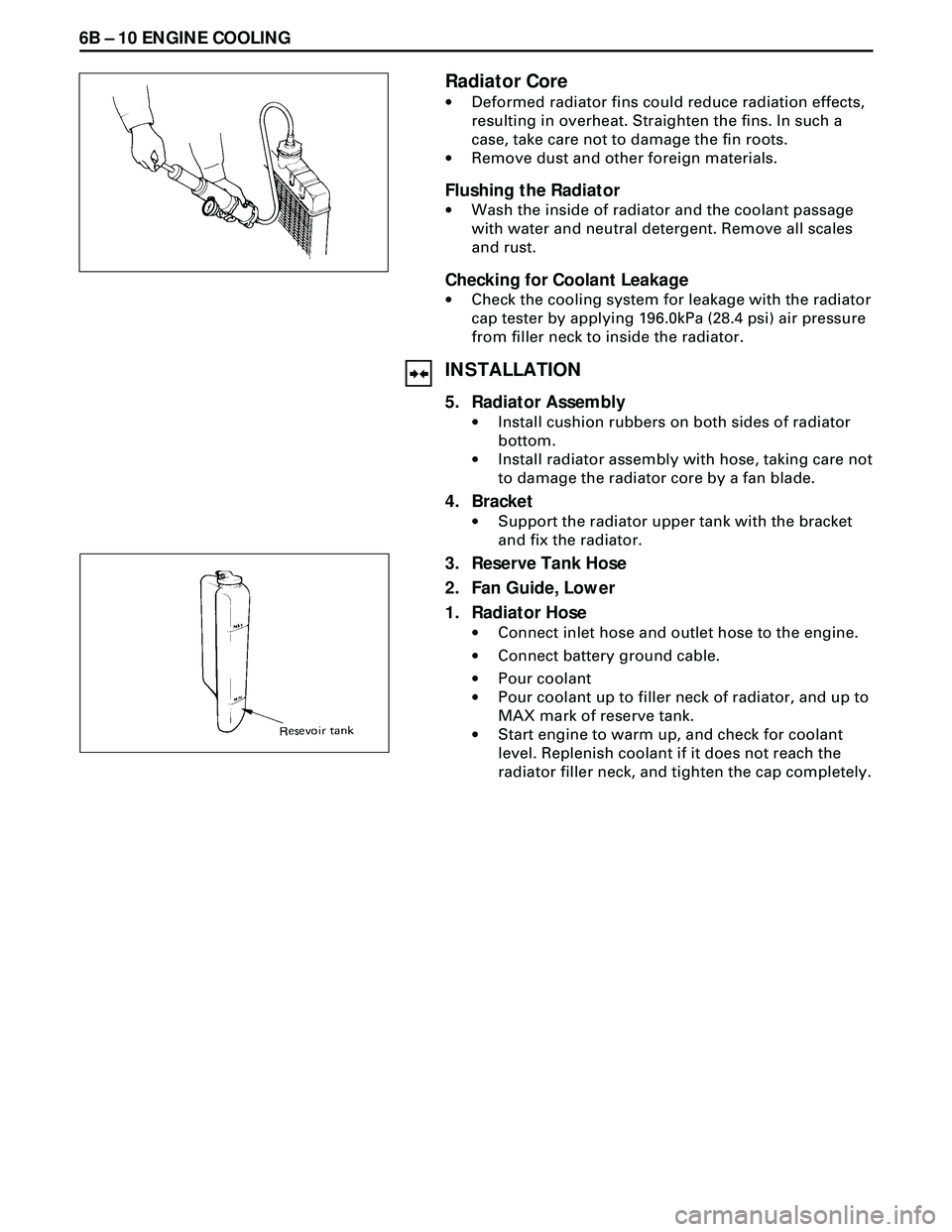
·Pour coolant
·Pour coolant up to filler neck of radiator, and up to
MAX mark of reserve tank.
·Start engine to warm up, and check for coolant
level. Replenish coolant if it does not reach the
radiator filler neck, and tighten the cap completely.
Page 1674 of 3573

6C Ð 8 FUEL SYSTEM
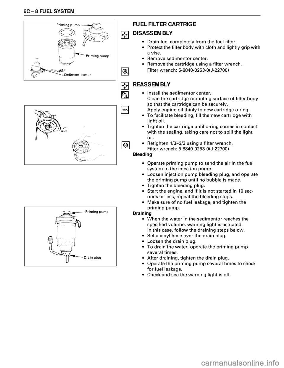
FUEL FILTER CARTRIGE
DISASSEMBLY
·Drain fuel completely from the fuel filter.
·Protect the filter body with cloth and lightly grip with
a vise.
·Remove sedimentor center.
·Remove the cartridge using a filter wrench.
Filter wrench: 5-8840-0253-0(J-22700)
REASSEMBLY
·Install the sedimentor center.
Clean the cartridge mounting surface of filter body
so that the cartridge can be securely.
Apply engine oil thinly to new cartridge o-ring.
·To facilitate bleeding, fill the new cartridge with
light oil.
·Tighten the cartridge until o-ring comes in contact
with the sealing, taking care not to spill the light
oil.
·Retighten 1/3~2/3 using a filter wrench.
Filter wrench: 5-8840-0253-0(J-22700)
Bleeding
·Operate priming pump to send the air in the fuel
system to the injection pump.
·Loosen injection pump bleeding plug, and operate
the priming pump until no bubble is made.
·Tighten the bleeding plug.
·Start the engine, and if it is not started in 10 sec-
onds or less, repeat the bleeding steps.
·Make sure of no fuel leakage, and tighten the
priming pump.
Draining
·When the water in the sedimentor reaches the
specified volume, warning light is actuated.
In this case, follow the draining steps below.
·Set a vinyI hose over the drain plug.
·Loosen the drain plug.
·To drain the water, operate the priming pump
several times.
·After draining, tighten the drain plug.
·Operate the priming pump several times to check
for fuel leakage.
·Check and see the warning light is off.
Page 1681 of 3573

FUEL SYSTEM 6C Ð 15
REMOVAL
Preparation:
·Disconnect battery ground cable.
·Drain coolant.
1. Air Cleaner Cover & Air Duct
2. Intercooler Assembly (4JG2-T ONLY)
· Refer to Intercooler Assembly removal.
3. Radiator Assembly
·Disconnect upper and lower hoses on the engine
side.
4. Cooling Fan Assembly
·Remove cooling fan asm and remove fan pulley
and spacer.
5. P/S Pump Drive Belt
·Loosen P/S pump lock bolt and adjust bolt remove
two drive belts.
6. AC Generator Drive Belt
·Loosen AC generator mounting bolt (under side)
and adjust, bolt and remove drive belt.
7. Timing Gear
·Refer to Timing Gear Removal
·Remove the loosened nut and fixing bolt and
remove the timing gear.
8.Fuel Filter Assembly
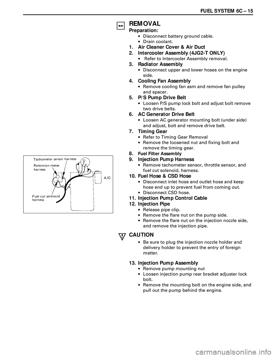
9. Injection Pump Harness
·Remove tachometer sensor, throttle sensor, and
fuel cut solenoid, harness.
10. Fuel Hose & CSD Hose
·Disconnect inlet hose and outlet hose and keep
hose end up to prevent fuel from coming out.
·Disconnect CSD hose.
11. Injection Pump Control Cable
12. Injection Pipe
·Release pipe clip.
·Remove the flare nut on the pump side.
·Remove the flare nut on the injection nozzle side,
and remove the injection pipe.
CAUTION
·Be sure to plug the injection nozzle holder and
delivery holder to prevent the entry of foreign
matter.
13. Injection Pump Assembly
·Remove pump mounting nut
·Loosen injection pump rear bracket adjuster lock
bolt.
·Remove the mounting bolt on the engine side, and
pull out the pump behind the engine.