1998 ISUZU TROOPER Cylinder head
[x] Cancel search: Cylinder headPage 26 of 3573
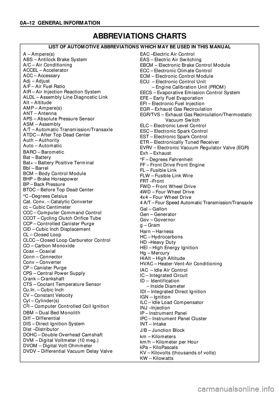
ABBREVIATIONS CHARTS
LIST OF AUTOMOTIVE ABBREVIATIONS WHICH MAY BE USED IN THIS MANUAL
A Ð Ampere(s)
ABS Ð Antilock Brake System
A/C Ð Air Conditioning
ACCEL Ð Accelerator
ACC Ð Accessary
Adj Ð Adjust
A/F Ð Air Fuel Ratio
AIR Ð Air Injection Reaction System
ALDL Ð Assembly Line Diagnostic Link
Alt Ð Altitude
AMP Ð Ampere(s)
ANT Ð Antenna
APS Ð Absolute Pressure Sensor
ASM Ð Assembly
A/T Ð Automatic Transmission/Transaxle
ATDC Ð After Top Dead Center
Auth Ð Authority
Auto Ð Automatic
BARO Ð Barometic
Bat Ð Battery
Bat+ Ð Battery Positive Terminal
Bbl Ð Barrel
BCM Ð Body Control Module
BHP Ð Brake Horsepower
BP Ð Back Pressure
BTDC Ð Before Top Dead Center
¡C ÐDegrees Celsius
Cat. Conv. Ð Catalytic Converter
cc Ð Cubic Centimeter
CCC Ð Computer Command Control
CCOT Ð Cycling Clutch Orifice Tube
CCP Ð Controlled Canister Purge
CID Ð Cubic Inch Displacement
CL Ð Closed Loop
CLCC Ð Closed Loop Carburetor Control
CO Ð Carbon Monoxide
Coax Ð Coaxial
Conn Ð Connector
Conv Ð Converter
CP Ð Canister Purge
CPS Ð Central Power Supply
Crank Ð Crankshaft
CTS Ð Coolant Temperature Sensor
Cu.In. Ð Cubic Inch
CV Ð Constant Velocity
Cyl Ð Cylinder(s)
C
3I Ð Computer Controlled Coil Ignition
DBM Ð Dual Bed Monolith
Diff Ð Differential
DIS Ð Direct Ignition System
Dist ÐDistributor
DOHC Ð Double Overhead Camshaft
DVM Ð Digital Voltmeter (10 meg.)
DVOM Ð Digital Volt Ohmmeter
DVDV Ð Differential Vacuum Delay Valve
EAC ÐElectric Air Control
EAS Ð Electric Air Switching
EBCM Ð Electronic Brake Control Module
ECC Ð Electronic Climate Control
ECM Ð Electronic Control Module
ECU Ð Electronic Control Unit
Ð Engine Calibration Unit (PROM)
EECS Ð Evaporative Emission Control System
EFE Ð Early Fuel Evaporation
EFI Ð Electronic Fuel Injection
EGR Ð Exhaust Gas Recirculation
EGR/TVS Ð Exhaust Gas Recirculation/Thermostatic
Vacuum Switch
ELC Ð Electronic Level Control
ESC Ð Electronic Spark Control
EST Ð Electronic Spark Control
ETR Ð Electronically Tuned Receiver
EVRV Ð Electronic Vacuum Regulator Valve (EGR)
Exh Ð Exhaust
¡F Ð Degrees Fahrenheit
FF Ð Front Drive Front Engine
FL Ð Fusible Link
FLW Ð Fusible Link Wire
FRT ÐFront
FWD Ð Front Wheel Drive
4WD Ð Four Wheel Drive
4x4 Ð Four Wheel Drive
4 A/T Ð Four Speed Automatic Transmission/Transaxle
Gal Ð Gallon
Gen Ð Generator
Gov Ð Governor
g Ð Gram
Harn Ð Harness
HC Ð Hydrocarbons
HD ÐHeavy Duty
HEI Ð High Energy Ignition
Hg Ð Mercury
HiAlt Ð High Altitude
HVAC Ð Heater-Vent-Air Conditioning
IAC Ð Idle Air Control
IC Ð Integrated Circuit
ID Ð Identification
Ð Inside Diameter
IDI Ð Integrated Direct Ignition
IGN Ð Ignition
ILC Ð Idle Load Compensator
INJ ÐInjection
IP Ð Instrument Panel
IPC Ð Instrument Panel Cluster
INT Ð Intake
J/B Ð Junction Block
km Ð Kilometers
km/h Ð Kilometer per Hour
kPa Ð KiloPascals
KV Ð Kilovolts (thousands of volts)
KW Ð Kilowatts
0AÐ12 GENERAL INFORMATION
Page 27 of 3573
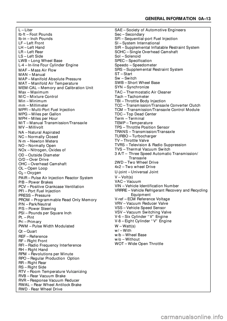
SAE Ð Society of Automotive Engineers
Sec Ð Secondary
SFI Ð Sequential-port Fuel Injection
SI Ð System International
SIR Ð Supplemental Inflatable Restraint System
SOHC Ð Single Overhead Camshaft
Sol Ð Solenoid
SPEC Ð Specification
Speedo Ð Speedometer
SRS Ð Supplemental Restraint System
ST Ð Start
Sw Ð Switch
SWB Ð Short Wheel Base
SYN Ð Synchronize
TAC Ð Thermostatic Air Cleaner
Tach Ð Tachometer
TBI Ð Throttle Body Injection
TCC Ð Transmission/Transaxle Converter Clutch
TCM Ð Transmission/Transaxle Control Module
TDC Ð Top Dead Center
Term Ð Terminal
TEMP Ð Temperature
TPS Ð Throttle Position Sensor
TRANS Ð Transmission/Transaxle
TURBO Ð Turbocharger
TV Ð Throttle Valve
TVRS Ð Television & Radio Suppression
TVS Ð Thermal Vacuum Switch
3 A/T Ð Three Speed Automatic Transmission/
Transaxle
2WD Ð Two Wheel Drive
4x2 Ð Two wheel Drive
U-joint Ð Universal Joint
V Ð Volt(s)
VAC Ð Vacuum
VIN Ð Vehicle Identification Number
VRRRE Ð Vehicle Refrigerant Recovery and Recycling
Equipment
V-ref Ð ECM Reference Voltage
VRV Ð Vacuum Reducer Valve
VSS Ð Vehicle Speed Sensor
VSV Ð Vacuum Switching Valve
V-6 Ð Six Cylinder ÒVÓ Engine
V-8 Ð Eight Cylinder ÒVÓ Engine
W Ð Watt(s)
w/ Ð With
w/b Ð Wheel Base
w/o Ð Without
WOT Ð Wide Open ThrottleL Ð Liter
lbáft Ð Foot Pounds
lbáin Ð Inch Pounds
LF Ð Left Front
LH Ð Left Hand
LR Ð Left Rear
LS Ð Left Side
LWB Ð Long Wheel Base
L-4 Ð In-line Four Cylinder Engine
MAF Ð Mass Air Flow
MAN Ð Manual
MAP Ð Manifold Absolute Pressure
MAT Ð Manifold Air Temperature
MEM-CAL Ð Memory and Calibration Unit
Max Ð Maximum
M/C Ð Mixture Control
Min Ð Minimum
mm Ð Millimeter
MPFI Ð Multi-Port Fuel Injection
MPG Ð Miles per Gallon
MPH Ð Miles per Hour
M/T Ð Manual Transmission/Transaxle
MV Ð Millivolt
NA Ð Natural Aspirated
NC Ð Normally Closed
Nám Ð Newton Meters
NO Ð Normally Open
NOx Ð Nitrogen, Oxides of
OD Ð Outside Diameter
O/D Ð Over Drive
OHC Ð Overhead Camshaft
OL Ð Open Loop
O
2Ð Oxygen
PAIR Ð Pulse Air Injection Reactor System
P/B Ð Power Brakes
PCV Ð Positive Crankcase Ventilation
PFI Ð Port Fuel Injection
PRESS Ð Pressure
PROM Ð Programmable Read Only Memory
P/N Ð Park/Neutral
P/S Ð Power Steering
PSI Ð Pounds per Square Inch
Pt. Ð Pint
Pri Ð Primary
PWM Ð Pulse Width Modulated
Qt Ð Quart
REF Ð Reference
RF Ð Right Front
RFI Ð Radio Frequency Interference
RH Ð Right Hand
RPM Ð Revolutions per Minute
RPO Ð Regular Production Option
RR Ð Right Rear
RS Ð Right Side
RTV Ð Room Temperature Vulcanizing
RVB Ð Rear Vacuum Brake
RVR Ð Response Vacuum Reducer
RWAL Ð Rear Wheel Antilock Brake
RWD - Rear Wheel Drive
GENERAL INFORMATION 0AÐ13
Page 130 of 3573
1B Ð 4 AIR CONDITIONING
The refrigeration cycle includes the following four
processes as the refrigerant changes repeatedly
from liquid to gas and back to liquid while
circulating.
EVAPORATION
The refrigerant is changed from a liquid to a gas
inside the evaporator. The refrigerant mist that
enters the evaporator vaporizes readily. The liquid
refrigerant removes the required quantity of heat
(latent heat of vaporization) from the air around the
evaporator core cooling fins and rapidly vaporizes.
Removing the heat cools the air, which is then
radiated from the fins and lowers the temperature
of the air inside the vehicle.
The refrigerant liquid sent from the expansion valve
and the vaporized refrigerant gas are both present
inside the evaporator and the liquid is converted to
gas.
With this change from liquid to gas, the pressure
inside the evaporator must be kept low enough for
vaporization to occur at a lower temperature.
Because of that, the vaporized refrigerant is sucked
into the compressor.
COMPRESSION
The refrigerant is compressed by the compressor
until it is easily liquefied at normal temperature.
The vaporized refrigerant in the evaporator is
sucked into the compressor. This action maintains
the refrigerant inside the evaporator at a low
pressure so that it can easily vaporize, even at low
temperatures close to 0¡C (32¡F).
Also, the refrigerant sucked into the compressor is
compressed inside the cylinder to increase the
pressure and temperature to values such that the
refrigerant can easily liquefy at normal ambient
temperatures.
CONDENSATION
The refrigerant inside the condenser is cooled by
the outside air and changes from gas to liquid.
The high temperature, high pressure gas coming
from the compressor is cooled and liquefied by the
condenser with outside air and accumulated in the
receiver/drier. The heat radiated to the outside air
by the high temperature, high pressure gas in the
compressor is called heat of condensation. This is
the total quantity of heat (heat of vaporization) the
refrigerant removes from the vehicle interior via the
evaporator and the work (calculated as the quantity
of heat) performed for compression.
EXPANSION
The expansion valve lowers the pressure of the
refrigerant liquid so that it can easily vaporize.
The process of lowering the pressure to encourage
vaporization before the liquefied refrigerant is sent
to the evaporator is called expansion. In addition,
the expansion valve controls the flow rate of the
refrigerant liquid while decreasing the pressure.
That is, the quantity of refrigerant liquid vaporized
inside the evaporator is determined by the quantity
of heat which must be removed at a prescribed
vaporization temperature. It is important that the
quantity of refrigerant be controlled to exactly the
right value.
COMPRESSOR
The compressor performs two main functions:
It compresses low-pressure and low-temperature
refrigerant vapor from the evaporator into high-
pressure and high-temperature refrigerant vapor to
the condenser. And it pumps refrigerant and
refrigerant oil through the A/C system.
6VD1/6VE1 engine on RHD model is equipped with
an invariable capacity five-vane rotary compressor
(DKV-14D Type).
The compressor sucks and compresses refrigerant
by the rotation of the vane installed to the shaft,
and always discharges a fixed amount of refrigerant
independent of the load of refrigerant.
The thermo sensor is installed to the front head of
the compressor to protect it by stopping its
operation when the refrigerant gas is insufficient or
when the temperature is abnormally high.
·OFF ....... 160 ±5¡C (320.0 ±41¡F)
·ON ........ 135 ±5¡C (275.0 ±41¡F)
Diesel Engine models and 6VD1/6VE1 engine on
LHD model are equipped with a swash plate type
compressor
Swash plate compressors have a swash (slanted)
plate mounted on the shaft. When the shaft turns,
the rotation of the swash plate is converted to
reciprocating piston motion which sucks in and
compresses the refrigerant gas.
Shaft seal (Lip type) is installed between the valve
plate and shaft & cylinder head to prevent
refrigerant gas leaks. A specified amount of
compressor oil is contained in the oil pan.
This oil is supplied to the cylinders, bearings, etc.,
by an oil pump which is connected to the swash
plate shaft.
Page 259 of 3573
COMPRESSOR OVERHAUL 1D Ð 3
solvent, and dried with dry air. Use only lint free
cloths to wipe parts.
The operations described below are based on
bench overhaul with compressor removed from the
car, except as noted. They have been prepared in
order of accessibility of the components. When the
compressor is removed from the car for servicing,
the oil remaining in the compressor should be
discarded and new refrigerant oil added to the
compressor.
Magnetic clutch assembly repair procedures require
that the system be discharged of refrigerant. (Refer
to Section 1B for ÒREFRIGERANT RECOVERYÓ.)
Compressor malfunction will appear in one of four
ways: noise, seizure, leakage or low discharge
pressure. Resonant compressor noises are not
cause for alarm; however, irregular noise or rattles
may indicate broken parts or excessive clearances
due to wear. To check seizure, de-energize the
magnetic clutch and check to see if the drive plate
can be rotated. If rotation is impossible, the
compressor is seized. Low discharge pressure may
be due to a faulty internal seal of the compressor,
or a restriction in the compressor. Low discharge
pressure may also be due to an insufficient
refrigerant charge or a restriction elsewhere in the
system. These possibilities should be checked prior
to servicing the compressor. If the compressor is
inoperative, but is not seized, check to see if current
is being supplied to the magnetic clutch coil
terminals.
The compressor has vanes built into a rotor which
is mounted on a shaft.
When the shaft rotates, the vanes built into the
cylinder block assembly are opened by centrifugal
force.
This changes the volume of the space formed by
the rotor and cylinder, resulting in the intake and
compression of the refrigerant gas. The discharge
valve and the valve stopper, which protects the
discharge valve, are built into the cylinder block
assembly. There is no suction valve but a shaft seal
is installed between the shaft and head; a trigger
valve, which applies back pressure to the vanes, is
installed in the cylinder block and a refrigerant gas
temperature sensor is installed in the front head.
The specified quantity of compressor oil is
contained in the compressor to lubricate the various
parts using the refrigerant gas discharge pressure.
6VD1 engine is equipped with an invariable
capacity five-vane rotary compressor (DKV-14D
Type).
The compressor sucks and compresses refrigerant
by the rotation of the vane installed to the shaft,
and always discharges a fixed amount of refrigerant
independent of the load of refrigerant.The thermo sensor is installed to the front head of
the compressor to protect it by stopping its
operation when the refrigerant gas is insufficient or
when the temperature get abnormally high.
·OFF ..... 160 ±5¡C (320.0 ±9.0¡F)
·ON ..... 135 ±5¡C (275.0 ±9.0¡F)
4JG2 Engine are provided with a swash plate type
compressor (DKS-15CH Type)
Swash plate compressors have a swash (slanted)
plate mounted on the shaft. When the shaft turns,
the rotation of the swash plate is converted to
reciprocating piston motion which sucks in and
compresses the refrigerant gas.
Shaft seal (Lip type) is installed between the valve
plate and shaft & cylinder head to prevent
refrigerant gas leaks. A specified amount of
compressor oil is contained in the oil pan.
This oil is supplied to the cylinders, bearings, etc.,
by an oil pump which is connected to the swash
plate shaft.
With some compressors the differential between
the intake pressure and discharge pressure
generated while the compressor is operating is
used for lubrication instead of an oil pump.
Three pistons are arranged at 120g intervals around
the center of the swash plate shaft. These pistons
are connected to the ends of the swash plate
through shoe disks and balls.
The rotation of the swash plate causes
reciprocating movement of the piston inside the
cylinders, with each piston operating as two
cylinders. Because of that, the compressor operates
as though it has 6 cylinders.
The specified amount of the compressors oil is
150cc (4.2 Imp fl oz).
Also, compressor oil to be used varies according to
the compressor model. Be sure to avoid mixing two
or more different types of oil.
If the wrong oil is used, lubrication will be poor and
the compressor will seize or malfunction.
Page 266 of 3573
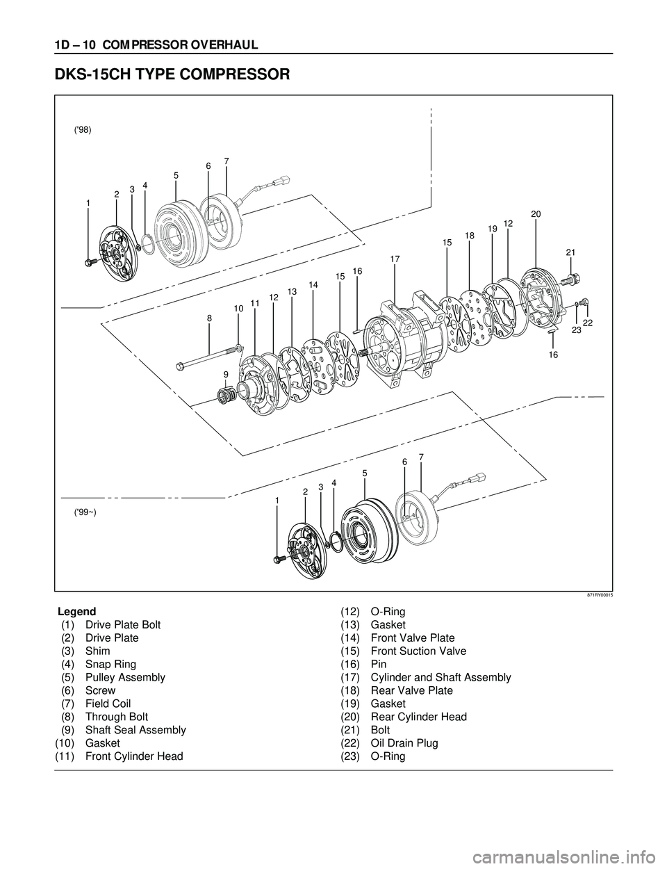
1D Ð 10 COMPRESSOR OVERHAUL
Legend
(1) Drive Plate Bolt
(2) Drive Plate
(3) Shim
(4) Snap Ring
(5) Pulley Assembly
(6) Screw
(7) Field Coil
(8) Through Bolt
(9) Shaft Seal Assembly
(10) Gasket
(11) Front Cylinder Head(12) O-Ring
(13) Gasket
(14) Front Valve Plate
(15) Front Suction Valve
(16) Pin
(17) Cylinder and Shaft Assembly
(18) Rear Valve Plate
(19) Gasket
(20) Rear Cylinder Head
(21) Bolt
(22) Oil Drain Plug
(23) O-Ring
DKS-15CH TYPE COMPRESSOR
16
23 2122 6
7
45
321 ('98)
('99~)
67
45
321
8
910111213141516
17
1518191220
871RY00015
Page 269 of 3573
COMPRESSOR OVERHAUL 1D Ð 13
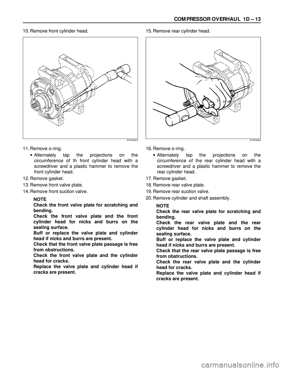
10. Remove front cylinder head.
11. Remove o-ring.
·Alternately tap the projections on the
circumference of th front cylinder head with a
screwdriver and a plastic hammer to remove the
front cylinder head.
12. Remove gasket.
13. Remove front valve plate.
14. Remove front suction valve.
NOTE
Check the front valve plate for scratching and
bending.
Check the front valve plate and the front
cylinder head for nicks and burrs on the
sealing surface.
Buff or replace the valve plate and cylinder
head if nicks and burrs are present.
Check that the front valve plate passage is free
from obstructions.
Check the front valve plate and the cylinder
head for cracks.
Replace the valve plate and cylinder head if
cracks are present.15. Remove rear cylinder head.
16. Remove o-ring.
·Alternately tap the projections on the
circumference of the rear cylinder head with a
screwdriver and a plastic hammer to remove the
rear cylinder head.
17. Remove gasket.
18. Remove rear valve plate.
19. Remove rear suction valve.
20. Remove cylinder and shaft assembly.
NOTE
Check the rear valve plate for scratching and
bending.
Check the rear valve plate and the rear
cylinder head for nicks and burrs on the
sealing surface.
Buff or replace the valve plate and cylinder
head if nicks and burrs are present.
Check that the rear valve plate passage is free
from obstructions.
Check the rear valve plate and the cylinder
head for cracks.
Replace the valve plate and cylinder head if
cracks are present.
871RY00019871RY00020
Page 270 of 3573
1D Ð 14 COMPRESSOR OVERHAUL
Installation
1. Install cylinder and shaft assembly.
·Clamp the cylinder shaft assembly in a vise.
The rear side of the cylinder shaft assembly must
be facing up.
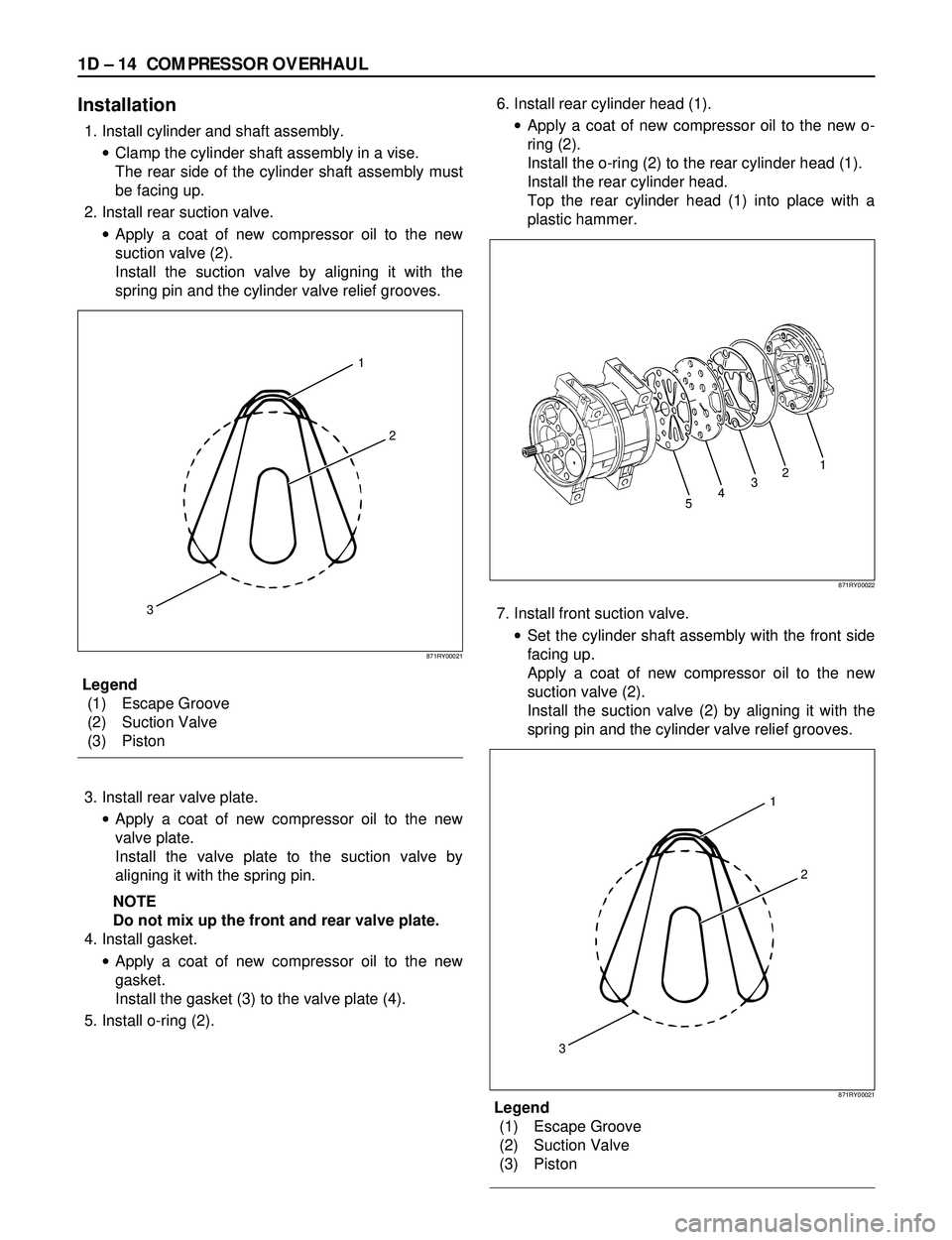
2. Install rear suction valve.
·Apply a coat of new compressor oil to the new
suction valve (2).
Install the suction valve by aligning it with the
spring pin and the cylinder valve relief grooves.
Legend
(1) Escape Groove
(2) Suction Valve
(3) Piston
3. Install rear valve plate.
·Apply a coat of new compressor oil to the new
valve plate.
Install the valve plate to the suction valve by
aligning it with the spring pin.
NOTE
Do not mix up the front and rear valve plate.
4. Install gasket.
·Apply a coat of new compressor oil to the new
gasket.
Install the gasket (3) to the valve plate (4).
5. Install o-ring (2).6. Install rear cylinder head (1).
·Apply a coat of new compressor oil to the new o-
ring (2).
Install the o-ring (2) to the rear cylinder head (1).
Install the rear cylinder head.
Top the rear cylinder head (1) into place with a
plastic hammer.
7. Install front suction valve.
·Set the cylinder shaft assembly with the front side
facing up.
Apply a coat of new compressor oil to the new
suction valve (2).
Install the suction valve (2) by aligning it with the
spring pin and the cylinder valve relief grooves.
Legend
(1) Escape Groove
(2) Suction Valve
(3) Piston
1
2
3
871RY00021
54321
871RY00022
1
2
3
871RY00021
Page 271 of 3573

COMPRESSOR OVERHAUL 1D Ð 15
8. Install front valve plate.
·Apply a coat of new compressor oil to the new
valve plate.
Install the valve plate to the suction valve by
aligning it with the spring pin.
NOTE
Do not mix up the front and rear valve plates.
9. Install gasket
·Apply new compressor oil to the new gasket.
·Install the gasket to the valve plate by a aligning it
with the spring pin.
10. Install o-ring.
11. Install front cylinder head.
·Apply a coat of new compressor oil to the new O-
ring.
Install the O-ring to the front cylinder head.
Install the front cylinder head.
Tap the front cylinder head into place with a
plastic hammer.
NOTE
When installing the cylinder head, be careful
that the end of the drive shaft does not
damage the shaft seal assembly surface in the
cylinder head.12. Install through bolt.
·Gaskets cannot reused. Always replace new
ones. Tighten the bolts to the specified torque a
little at a time in the sequence shown in the
illustration.
Torque: 22Nám (16 lbáft)
NOTE
Rotate the compressor drive shaft two or three
times to make sure that it moves smoothly.
1
4
5
2
3
6
871RY00016
871RY00023